

Walls: Layers, location lines and functions
In Modelical, we use our own programmed tools to automate the task of putting the finishes of the rooms. The walls modelling strategy, although it seems very simple, is of vital importance in coordinating their joints and possible subsequent amendments. Next I expose some issues and procedures to consider.
Walls are a system family composed in its structure by several layers of different materials and thicknesses.
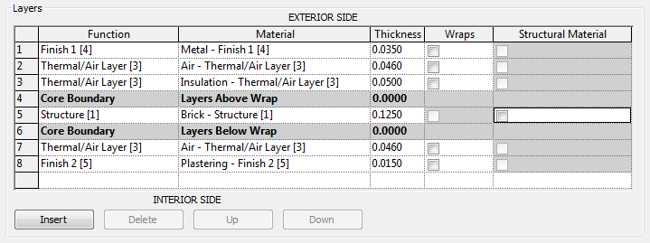
Layer functions
There are 6 different functions to choose from. All of them have correspondence with floors, roofs and ceilings. You cannot create, rename or delete functions.
- Structure [1]: Layer that supports the remainder of the wall, floor, or roof.
- Substrate [2]: Material, such as plywood or gypsum board, which acts as a foundation for another material.
- Thermal/Air Layer [3]: Provides insulation and prevents air penetration.
- Finish 1 [4]: Typically mandatorily used as exterior layer.
- Finish 2 [5]: Typically mandatorily used as interior layer.
- Membrane Layer: A membrane that commonly prevents water vapor penetration. The membrane layer should have zero thickness.
The most important thing we need to know on its functioning is the number in brackets [x]. This number indicates the priority of the layers in the joints, leading to proper cleansing of them.
There are some basic rules regarding this priority. For example:
- Layers with priority [1] will be in a join with another layer of priority [1], crossing for it any other layer in its path.
- Layers having a lower priority cannot cut layers with a higher priority.
- There is one exception to the above two rules. If the layer is located within the limits of the core, they can cut elements of higher priority that are outside the core of the other wall.
Location lines
Walls, once defined its height and composition, are drawn in plan view from two insertion points that define their location line. This line characterizes the location of the wall layers on its sides. There are six possibilities, namely:
- Finish Face: Exterior.
- Core Face: Exterior.
- Wall Centerline.
- Core Centerline.
- Core Face: Interior.
- Finish Face: Interior.

Depending on the position of the wall in the building, will be more appropriate to use one or another line location. For example, it seems logical that placing a facade wall at the boundary of the site, the option chosen is “Finish Face: Exterior” to never invade the outside of the parcel.
If we have already modelled the edge of a slab and we put a ventilated facade wall as the one in the image, the right thing would be to locate the wall by “Core Face: Exterior”, in order to have the core of the wall always resting on the slab.
If the target of the BIM model is to get the Bills of Quantities and/or to have a 4D planning, the way for modelling this wall has to be different, becoming three independent walls with their faces in contact.

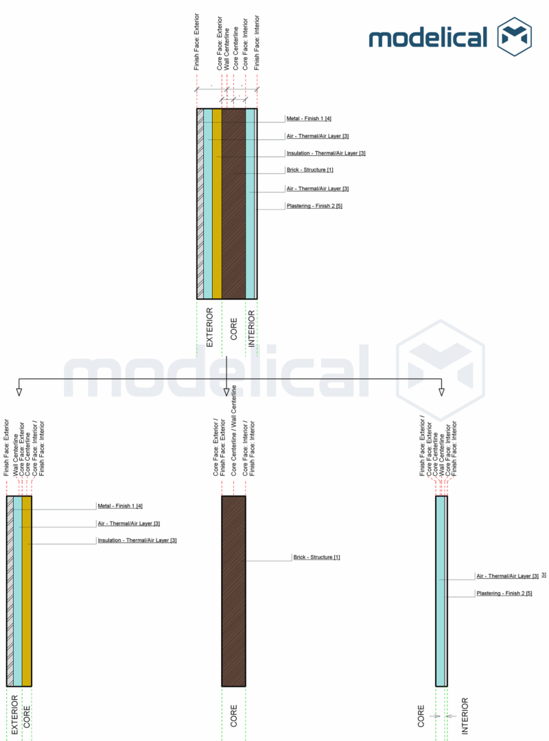
This situation results in 4 types of wall by their use: supporting walls, facade claddings, wall linings and finishes.
In the supporting walls, a determination has to be taken and you have to be consistent with it: what layers we put on the interior side and what layers the exterior side. My choice is to put single or especial layers (WR/FF) on the interior of the wall and regular or double layers on the exterior. Location line will vary depending on its position: wall centerline, finish face exterior or finish face interior.
In facade cladding we will put the layers on the exterior side and we will use the location line “finish face interior”.
In lining walls we will put the layers on the interior side and we will use the location line “finish face exterior”.
In finishes, as in cladding walls, layers should be located on the interior side of the Wall, remembering to use “Substrate [2]” function for the bonding material and “Finish 2 [5]” function for finishes layers. Location line must be “Finish face exterior”.
In summary, it’s very important that everyone involved in the project know what the adopted strategy to create and locate walls is. It should even adding a paragraph to the BEP explaining what the adopted decision is, so anyone who comes aboard to the work team can use it as a modelling guide.