
Assemblies and Parts
Operation in Revit
Assemblies
File: OPE_Assemblies
Objectives
To understand the possibilities of working with assemblies in Revit Models. They are a useful tool to document the project in detail design and construction phases of it.
Prerequisites
- User will be using Revit, any version.
- User has advanced skills in modelling, and understand the use of groups.
- User can create schedules.
- User can annotate views and create sheets.
Description
Assemblies in Revit is a category of elements that looks similar to groups but is actually quite different in behaviour and associated tools and actions.
An assembly is a combination, a unique combination of any number of model elements, that are grouped together and can be edited, tagged, scheduled and filtered, so that assemblies can be identified and quantified.
As groups, each unique assembly is listed as a type in the Project Browser. As groups, assemblies can be placed and copied across the model, but unlike groups, when an assembly is edited, changes are not spread across all the items of that assembly, but a new one is created.
Additionally, and this is very special from assemblies, you can create specific views as well as parts lists, material takeoffs, and sheets for every unique assembly type.
Procedure
Create assembly
Tool for creating assemblies is next to the group icon in the Modify Tab > Create Panel.
The assembly creation option works similar to the group creation.
You can select the objects that are going to be part of the assembly, and then create the assembly by using the assembly tool.
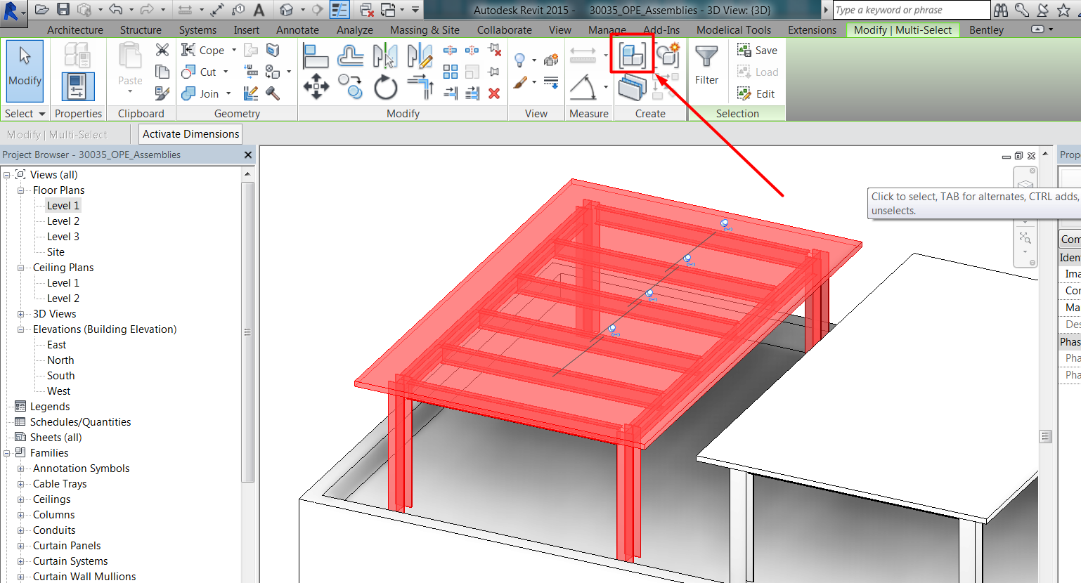
Or you can directly use the assembly tool and later add elements to the assembly:
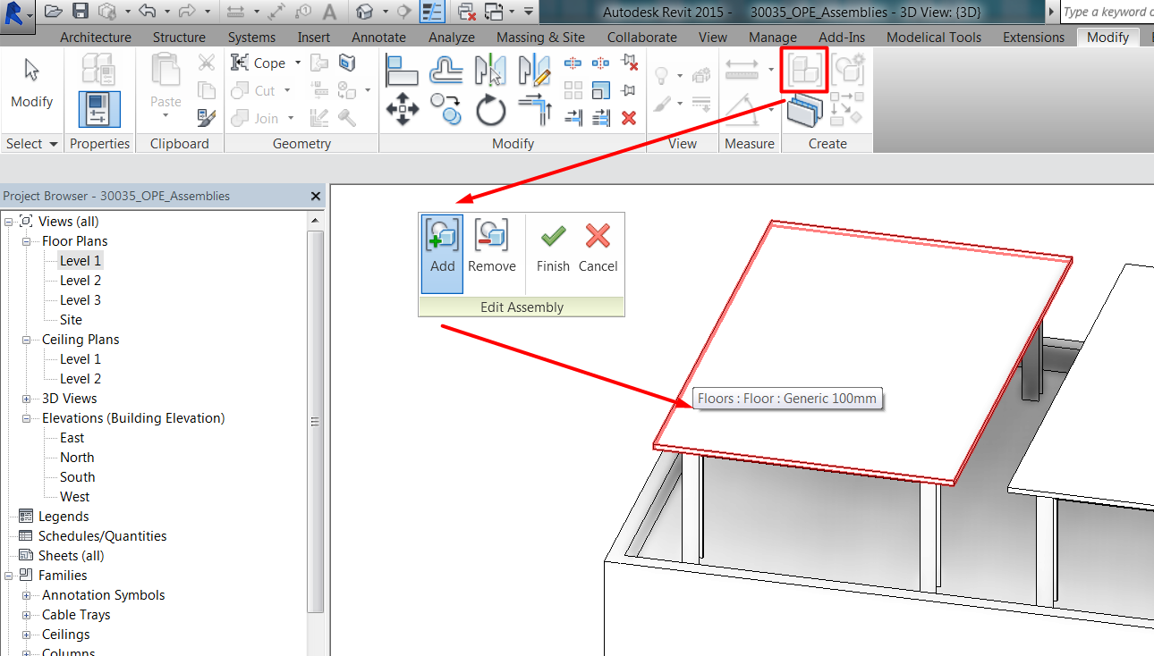
After an assembly has been created, it can be selected and further edited, to add new elements, or to modify the ones already in the assembly instance. To edit the assembly instance it has to be selected in the model.
When creating an assembly, it happens that:
User has to assign a category to the assembly. Categories available to be assigned to the assembly are those of the objects that are part of the assembly.
User has to assign a name to the unique assembly.
Unique assemblies will appear in the project browser in the Assemblies Section. User can drag them from the browser to place assemblies into the model, same as can do with families and groups.
Elements included in assemblies
Not every element can be included in an assembly. Here is a list of categories:
CAN BE INCLUDED | CANNOT BE INCLUDED |
Basic walls | Stacked walls |
Floors | Curtain Walls |
Roofs | Beam Systems |
Loadable model families | Curtain Systems |
Parts | Trusses |
Stairs by sketch | Stairs by component |
Other assemblies | |
Groups | |
Links | |
Annotations | |
Detail Items | |
Masses | |
Railings | |
Rooms / Spaces / Zones | |
Model Lines | |
Structural Loads | |
MEP Specific elements (ducts, pipes, conduits, trays, fittings) |
When objects that cannot be included in assemblies are selected, assembly will be created but automatically excluding those objects.
It has to be clarified that complex objects such as trusses, curtain walls, beam systems, curtain walls, and so on, cannot be included in assemblies, but their component elements can be included instead:
- Panels and mullions of curtain walls and systems can be included.
- Beams in beam systems and trusses can be included.
Matching assemblies
As said, each time you create a unique assembly, a new assembly type is added to the Project Browser.
As previously said, assemblies do not behave as groups. When an existing instance of an assembly is edited, a new assembly type will also be added to the project browser, as it becomes unique. This means that changes are not propagated across instances of the same assembly, but changes in assemblies cause the creation of a new type of assembly.
Sometimes, if a new or edited assembly exactly matches an existing assembly type, it is added to the model as an instance of that type. In those cases, when creating the assembly and choosing the naming category, the name of the assembly will be automatically populated with the name of the existing matching assembly:
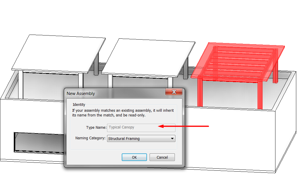
For Revit to recognize assemblies as matching, they must meet the following criteria:
- They must have the same value for the Naming Category property.
- They must include the same number of elements of the same categories and types with the same values for properties that affect geometry.
- Corresponding elements must occupy the same positions within each assembly.
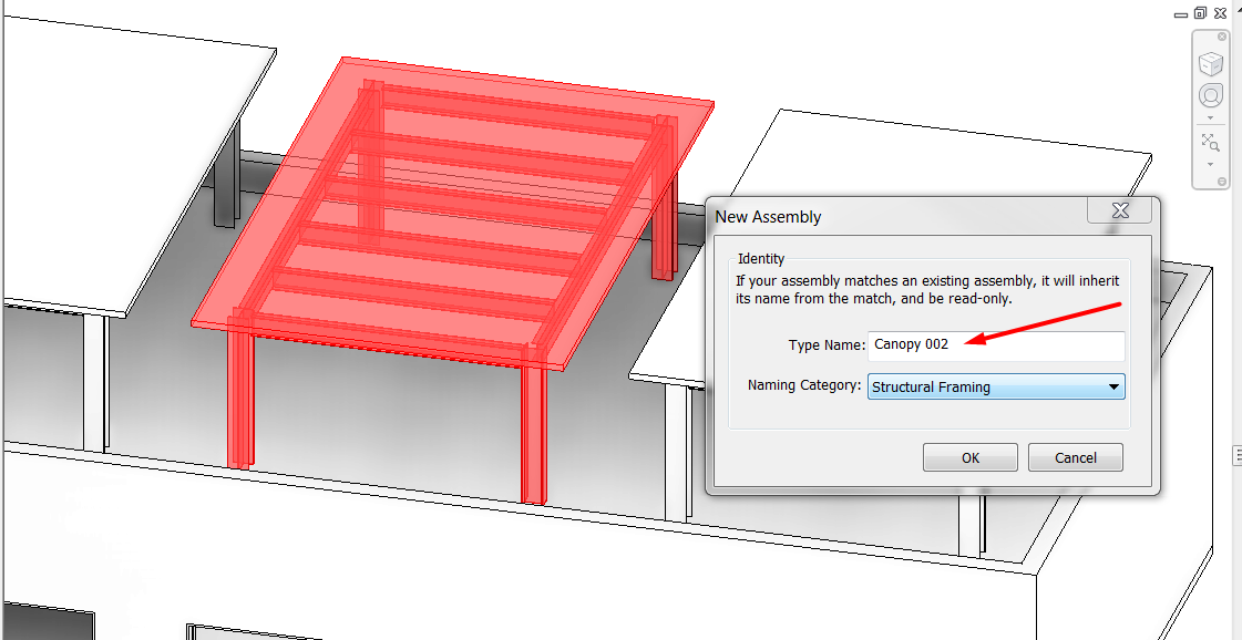
For a new assembly to match exactly an existing one, it also depends on how elements were created in model. If the elements of a selection seem to be the same as elements in an assembly but
- were placed by mirroring them, they won’t match the existing assembly, and a new type of assembly will be created.
- If they were copied, they will match the existing assembly.
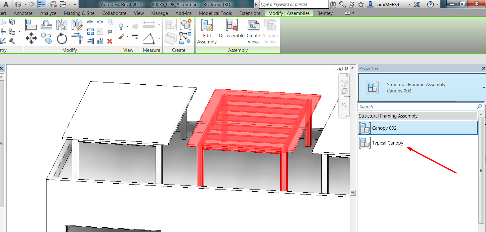
As groups and families, an assembly can be replaced by other type by using the Match Attributes tool, or simply by changing type in the selector type:
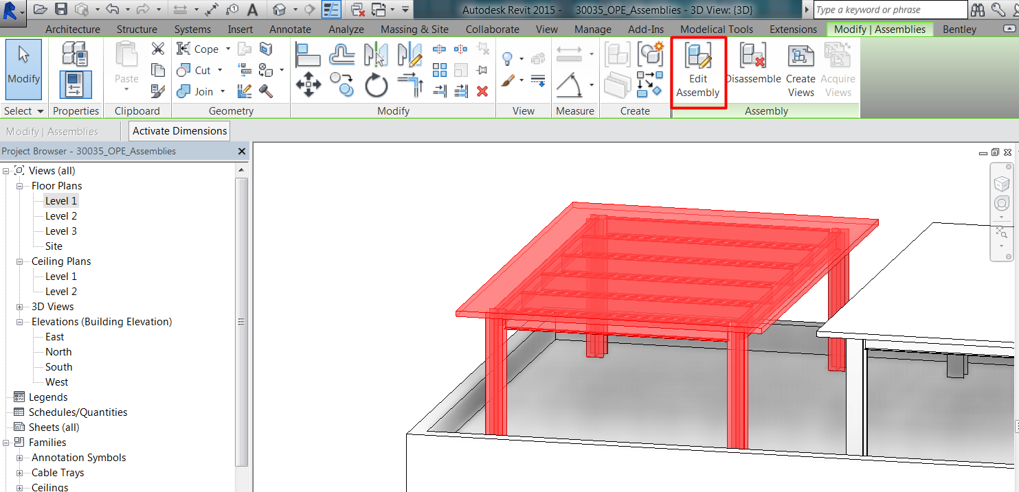
Edit assemblies
As previously said, once an assembly is created and placed, we can edit it.
We can add or remove assembly elements.
We can edit the assembly origin. The origin determines the orientation of the assembly in relation to the project orientation. The planes of the origin determine how the assembly is oriented in the corresponding elevations when you create the assembly. When we change the type of an assembly instance, the origin of the new type is applied to that instance.

The assembly origin can be selected when editing the assembly and be dragged or rotated to a new position.
We can also change the type of an assembly or several assemblies, by using the type selector.
We can edit an element in the assembly, by opening the assembly and editing the element, or also by selecting the element from outside the assembly, pressing tab until the element we want to edit is highlighted, and then editing it.
In any of the two previous options, if you edit an element in one instance of the assembly, if there are other instances placed in the model, it will cause a new type of assembly to be created.
If there is only one instance of an assembly and an element in it is edited, no new assembly type will be created.
Disassemble
Assemblies can be disassembled. User can remove the relationship between individual elements of an assembly at any time, in a similar way to ungrouping elements, and have the following effects:
The disassembled elements remain in the model. Other instances of the same assembly type are unaffected.
If the assembly that you disassemble is the last or only one of its type, then that type and any of its associated assembly views are removed from the project.
If the assembly that you disassemble is the instance that has views associated, those views will be deleted. You will get a warning:
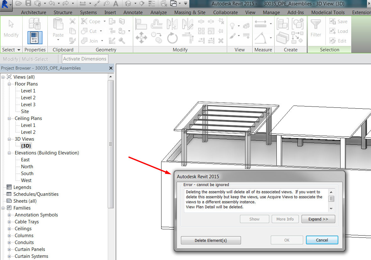
If you want to disassemble the assembly instance with the view associated, you can assign first the views to other assembly instance prior to disassembling:
Delete
Assembly instances can be deleted.
When you delete an assembly instance, all elements within the assembly are deleted.
If you delete an assembly instance, other assembly instances of the same type are not affected.
If you delete the last instance of an assembly type, the type will also be deleted.
When you delete an instance for which assembly views have been created, the views will be deleted from the project unless you first transfer them to another instance of the same assembly type (same as when disassembling).
When you delete an assembly type from the project browser, all instances of that assembly are deleted as well as any associated assembly views or sheets.
Assembly views and sheets
One of the interesting features of assemblies is that you can automatically create views that are associated to that combination of elements in the model.
User can document assemblies independently from the rest of the model, and that is why they can be very useful for detail design and construction documentation workflows.
Assembly views will be listed in the Assembly section of the project browser under the corresponding assembly type, and not in the general section for general views.
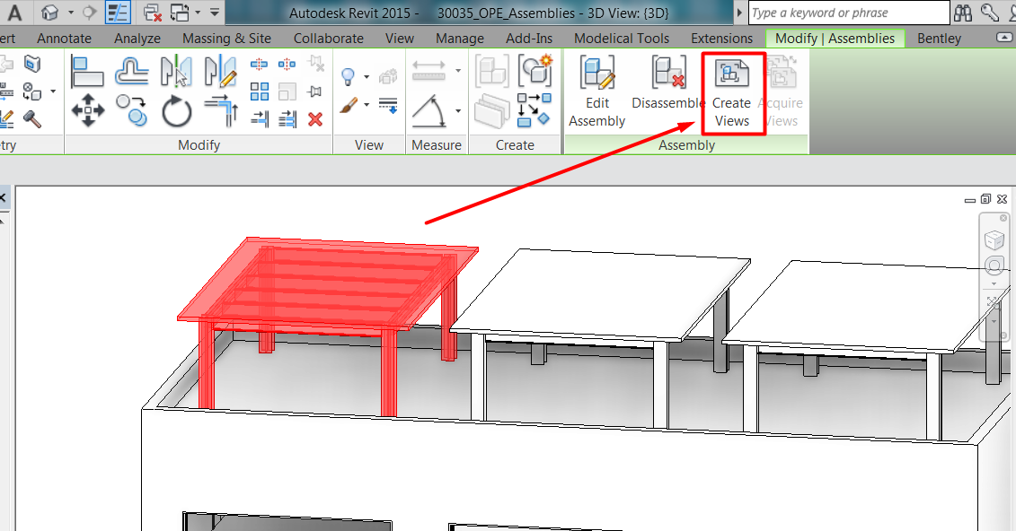
You can create assembly views and assembly sheets for each assembly type. These drawings are always associated with a particular instance of the type, and only one instance of a type can have assembly views.
If you create the views by first selecting one instance of the assembly type, views will be associated to that instance.
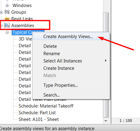
If you create views for an assembly type from the project browser, views will be associated by default with the first instance of the assembly.
If the instance of the assembly with the views associated is deleted from the project (or disassembled), all associated assembly views are deleted as well. If necessary, you can change the instance the views are associated with, as previously said.
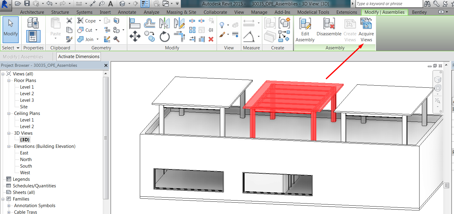
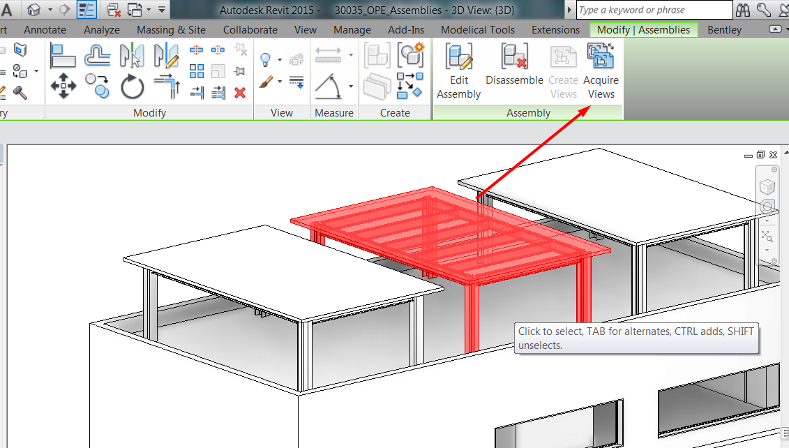
Views can only be created from one instance of an assembly type. Once they are associated with one of the instances, they cannot be created from another instance from the same assembly type, they can only be re-associated or acquired:
Assembly views always remain associated with the assembly instance for which they were created. If an edit to an assembly instance causes the instance to change from one assembly type to another, any assembly views belonging to the edited instance will be listed under the project browser node for the new assembly type. If the type you changed to already has assembly views, an error message informs you that one set of views will be deleted.
Assembly views include only objects that belong to assembly types. Any other element of the model is excluded and cannot be displayed.
Type of views and settings
You can create different types of views for each assembly type, same scale for all of them, or different scales if you create them not all at once. Views available are:
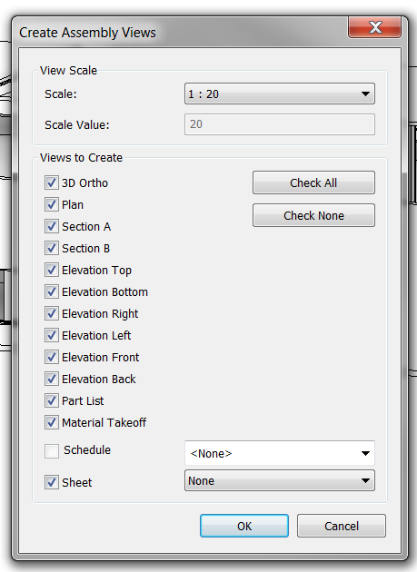
- In the Create Assembly Views dialog, you select the types of views you want.
- Select the desired scale.
- Specify title block information if you select the sheet option.
If you create additional section views within an assembly view, they inherit the assembly view's relationship to the assembly instance.
As in other views, all types of annotations and detail components can be added to these views to complete project and assembly documentation.
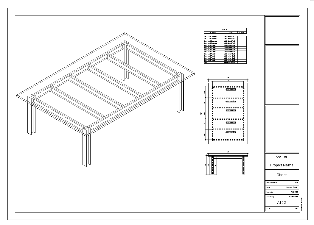
Sheets
Specific sheets are created by this method for assembly types, and they will be saved also under the assembly type name section of the project browser.
Sheets are created with no views on them.
To place an assembly view on an assembly sheet the procedure is equal as with regular views and sheets: drag the assembly view onto the assembly sheet.
Nevertheless, note that assembly views can also be placed on normal (non-assembly) sheets.
Schedule Assemblies
Quantities/TakeOff Schedule
Assemblies, as any other categories can be scheduled.
The Assemblies schedule lists all assembly instances in the model instead of the elements in the assembly.
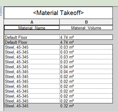
Assembly view “Schedule:Material Takeoff” lists the materials of the elements included in one assembly instance.
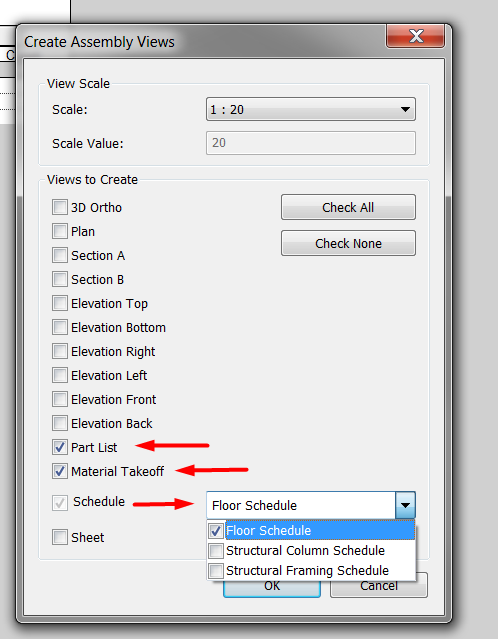
Assembly schedules
Additionally to regular category schedules, there are some assembly type specific schedules, that can be created as any other views associated to assembly types.
Part List lists the elements included in one assembly instance.
Assembly “Material Takeoff” lists the material of the elements of all assembly instances in the project.
User can create also specific category schedules for the assembly.

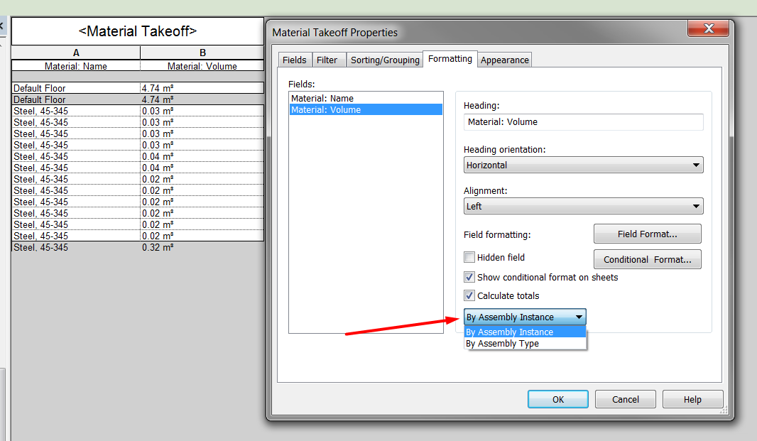
One important thing to notice when working with Assembly type schedules (quantities or take-off schedules), is that in general they work as any other schedule but in regards to field totals, you could sum up:
Elements of only ONE instance of the assembly type.
Elements of ALL instances of the assembly type.
Tips&Tricks
- Keep track of the assembly that has the views associated. If there is no way to know which one it is, create new views always from project browser right-click menu.
- Remember that editions in assemblies are not propagated across all instances of the same assembly type. That is how groups work, not assemblies.
- Assemblies can be very useful for project documentation, specially for structural complex elements like trusses and frames.
- A great number of assemblies in projects can affect model performance, in the same way as groups. Use assemblies carefully and delete those assembly types and views that are unused.
Bottom-line
Assembly tools in Revit help to work with complex elements in projects that are a combination of other simple elements but actually form a whole. With assembly tools they can be properly documented and user can keep track of them.
Associated Files
- 30035_OPE_Assemblies.rvt
- 30035_OPE_Sheet Layout GUIDELINE
- 30035_GEN_Schedules GUIDELINE
- 30035_GEN_Views GUIDELINE
Thank you. Very helpfull.