
Automatic modeling from point clouds
Myths, realities and what to expect in the future
Automatic modelling from point clouds
Introduction
The first and most obvious thing to emphasise is that to model/build you have to use your brain.
It is very difficult for automatic/semi-automatic modelling to reason constructively as a human would. Where it can help us is with repetitive tasks that do not add value to the work. An automatic modelling will not be able to make a rational fitting of structural grids, but it can help us to determine the thickness of a wall or the diameter and axis of a pipe.
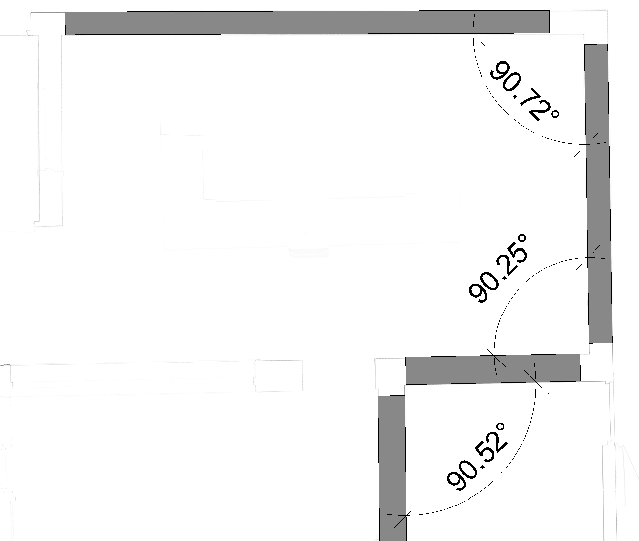
Depending on the use we want to give to the model we can automate more or less operations. The crux of the matter is to correctly manage the tolerances allowed in the model. For example, if we are making a model of the structure of a building we do not want to find a situation like the one in the image, in which no structural column axis is aligned with any other, because it would make it difficult to obtain an analytical model.
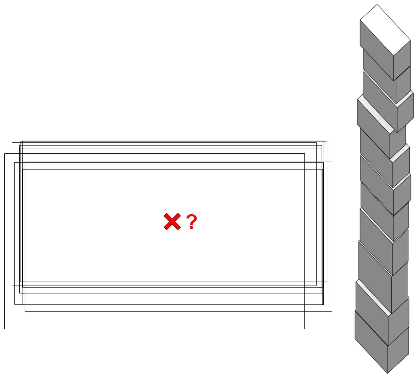
Instead, it is preferable to make an analysis of the alignment of these columns together with the rest of the columns of the same span to obtain a plan to which we can align all the columns, beams and slab openings of the model.
Myths
For several years now, with the widespread adoption of point clouds as the basis for digitising buildings, there has been a pressing enthusiasm for the emergence of digital tools to help us model with as little effort as possible. We are used to seeing how buildings are designed and modelled parametrically in which, just by defining the algorithms that devise them, all the elements that conform, for example, the envelope of a building, appear right away and with absolute precision. The observation of this phenomenon makes us extrapolate this idea directly to the possibility that the elements that conform a building are generated "by magic" from the point clouds.
Nowadays it is still a utopia to think that such a result can be achieved, and with the quality that we could imagine. For this reason, software developers are focused on designing tools that allow us to model in the easiest possible way, with an "assistant" that helps us to fit the constructive elements in the point cloud.
Realities
At the time of writing this article there are at least three tools with a degree of development that allows us to do semi-automatic modelling on point clouds. These are:
From Modelical we have been comparing the different approaches to solve this task. As our main modelling software is Revit, we have focused our look on how to make the transfer to this program. As a test subject we have used our office.
This article is not intended to be a comparison of the tools available but a description of the aids they offer to assist us in our work.
Elements that can be automated
Following Pareto's law, developers have focused on 20% of the construction elements that represent 80% of the building's volume. Thus we find that in the scope of architecture they have focused on walls, doors and windows, leaving aside furniture, for example. In the scope of the structures, they have focused on columns and beams, and in the facilities, mainly on piping.
We miss in the disciplines of architecture and structure the option of automating sketch-based construction elements, such as floors, although we understand the complexity of defining their boundaries.
In the case of facilities, it is rare that we can scan the elements in 100% of its surfaces. We always have some hidden faces because the element is attached to a slab or a wall. For this reason we understand that it is relatively easy to fit the circumference of a pipe with a partial section of its points, but it is difficult to know, for example, the two dimensions of a rectangular duct if we only see 2 or 3 of its faces.
In general, with one user interface or another, the procedure is very similar. The selection is made with one or two clicks of the element we want to model having as background the point cloud, and the wizard will evaluate the dimensions of the element and will present us with a list of types that fit those dimensions. For example, selecting a wall will show us the detected thickness, it will propose to us from the list of available walls the one that best fits and it will even give us the option to create a new type adjusting the thickness to the one detected in the point cloud.
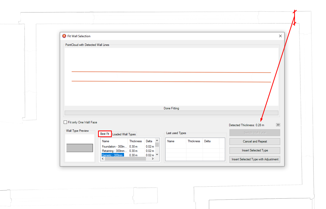
Once the appropriate type is selected, the wall will be automatically modelled following the alignment that best matches the orientation of the points.
Alignment to orthogonal/project axes
Initially, all tools prioritise modelling accuracy over usability. In some cases, when we want to be as faithful as possible to reality, this geometric rigour will be useful.
However, in most cases and if the required modelling tolerances allow it, the main interest will be to build a theoretical model that allows us to work more efficiently. For example, if we can get the walls that when we are visiting the room seem parallel or perpendicular to each other are also parallel in the model, it will facilitate the work in all subsequent steps, such as putting a dimension between two walls (if they are not parallel we will not be able to achieve it).
In this aspect there are two solutions applied by the softwares: make the decision before starting to model and choose the rules of adjustment to orthogonal axes a priori or adjust these alignments once the elements are modelled. In our opinion it is more interesting to be able to apply the adjustments a posteriori, because it allows you to be finer when choosing which walls to adjust. It does not have the same implication to rotate a 50cm wall one degree than a 50m wall the same angle, at the extremes the absolute displacement will be 100 times larger proportionally.
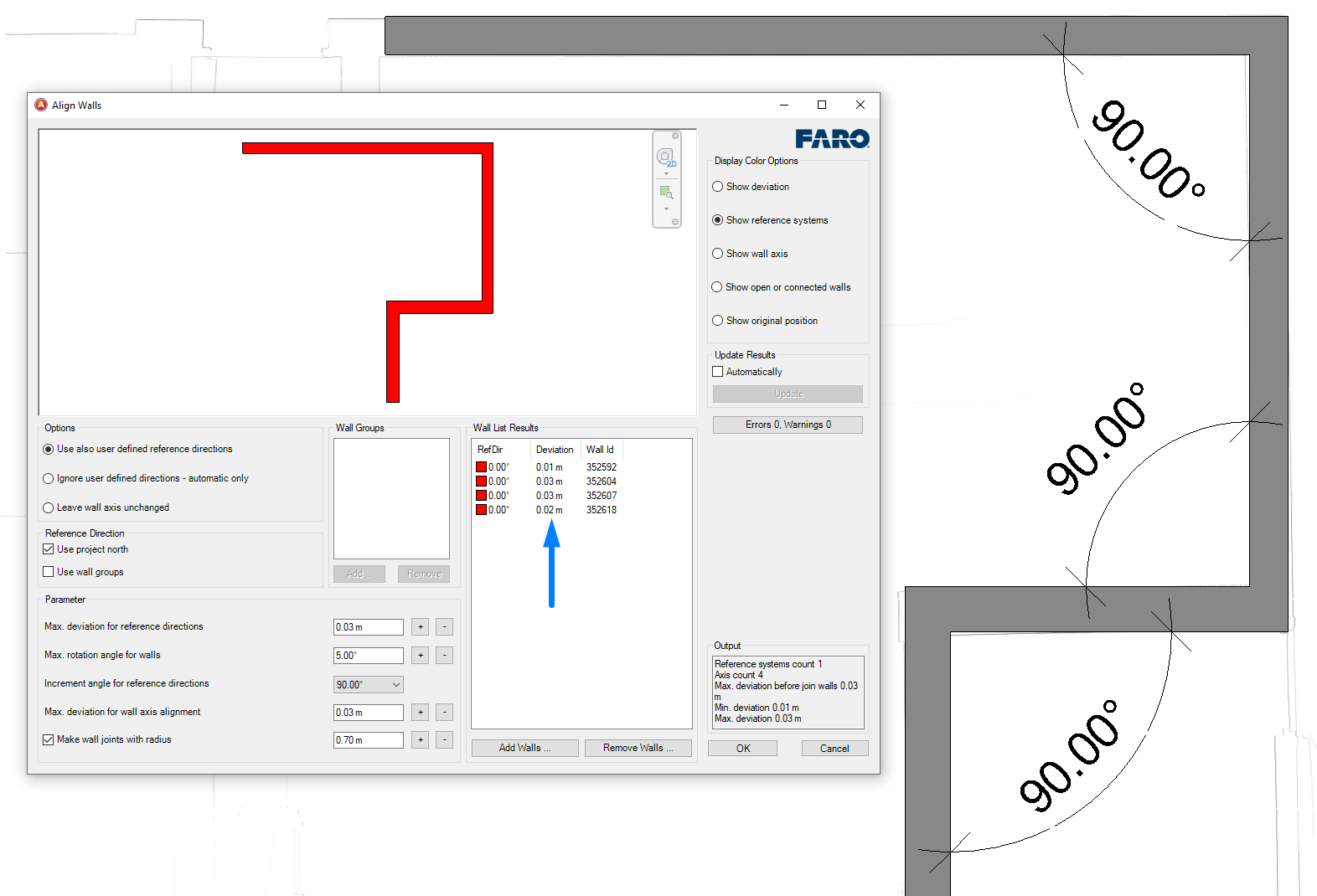
As shown in the image, the program has helped us to adjust the alignment of the walls to the orthogonal axes of the project and also presents data with the deviation of each of the walls, so we can always exclude from this process those walls that are outside the accepted tolerance.
Accuracy of modelled elements
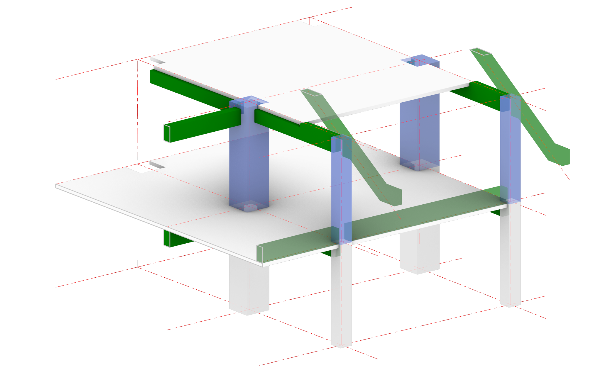
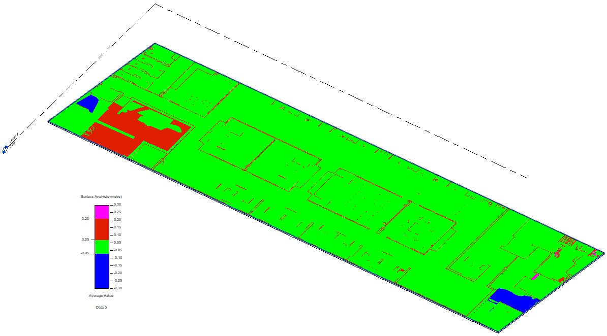
Something important for us is to know how accurate we have been with the modelling, and if there are misalignments due to deformations in the construction elements. For example, an analysis that we have performed during our tests is the flatness check of the floor. In the image you can see in red an area that has a10 cm raised floor and the blue areas where there is a slight ramp.
Some of the tools we have tested allow us to make this kind of checks, but always in a localised way. As part of another article we will evaluate different methods not only to check that the model has enough accuracy, but also to check another different but very similar casuistry: to check that what has been executed on site according to a three-dimensional model is in the correct location and with the right dimensions.
The near future
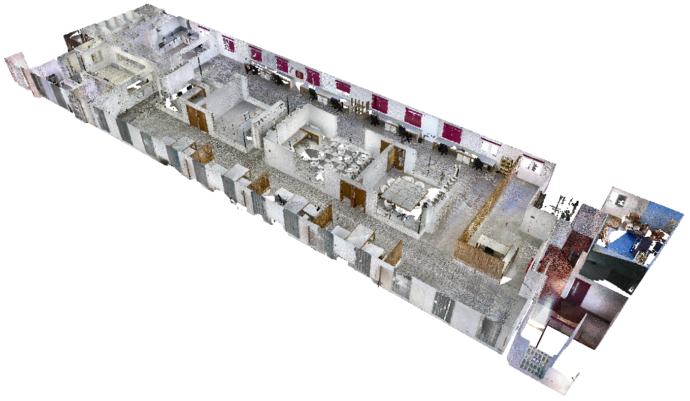
When we scan a building we obtain as a result millions of points, but those points have no information about the element they are describing. The same point (x, y, z) can be on the surface of a column, door or ceiling.
The main challenge currently facing software developers in automatic modelling is to be able to segment point clouds by adding constructive semantics to them.
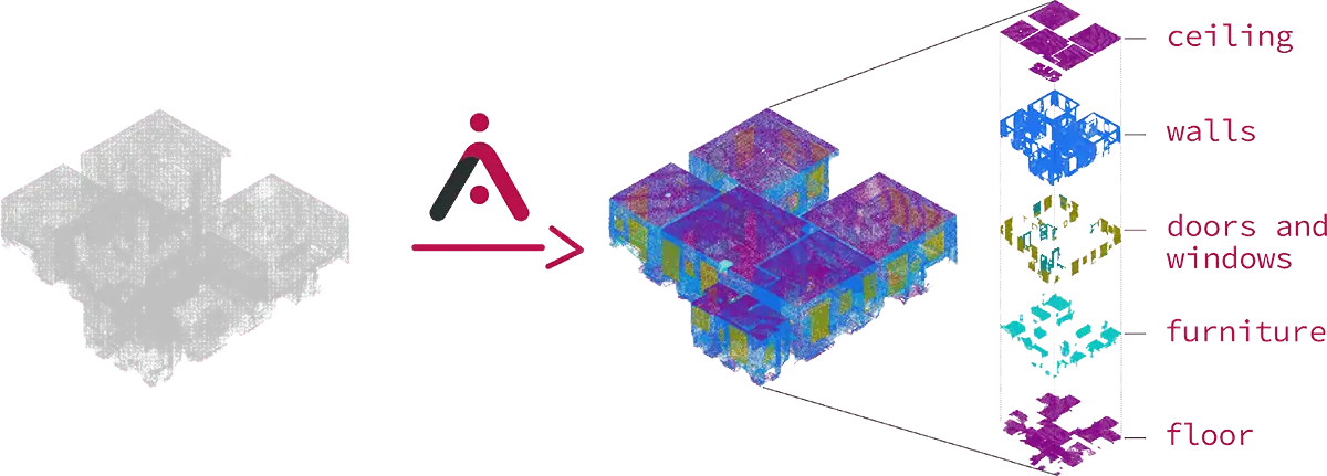
As explained in this image of aurivus.com, with machine learning and artificial intelligence processes they are trying to split a complete point cloud into sets of points belonging to the same building element. Once this is achieved, we could apply computer-aided modelling techniques automatically on these sets of points, ideally obtaining a complete model of the building. As we said at the beginning of this article, on many occasions the intervention of a human will be necessary to solve conflicts in the computer's decisions, or to explain to the software how it should interpret complex situations due to the ambiguity of the construction: is it a structural wall or a screened column? A curtain wall mullion or a beam?
And finally, a thought: is it totally necessary to model the objects represented in the point cloud? Or would adding metadata to sets of points be enough in some cases (historical buildings, for example)?
I see near the moment where the constructive surveys are done automatically, at least in volumetric terms