
Create Parts
Operation in Revit
Parts
Objectives
To understand the possibilities of working with parts.
Prerequisites
- User will be using Revit, any version.
- User has advanced skills in modelling and view management.
Description
Parts is a tool that was introduced in Revit 2012 to support construction modelling workflows, but it can be useful as well for interior design detailing.
For both intentions, the process is the same and the concept is simple. Parts allow the user to divide major model elements into more discrete parts that represent modular building components or element construction subdivisions. It allows to have a more detailed model for project documentation, precise quantity take-off and constructability checking.
Parts can be independently scheduled, tagged, filtered and exported.
There are two interesting things about parts:
- The original element from which parts are derived is preserved in the model. In each view we can visualize either the original element, the derived parts, or both simultaneously. Besides, any changes in original component will be propagated to the related parts, although modifying a part will not have any effect on the original component.
- More surprising is that Parts work through links. This means that if we have a link loaded, we can select one element of the link and create parts from it, and work with them as if they were derived from a component directly in the model. But the link will not be modified.
Parts can be created from layered system families or some loadable structural families:
- Walls (excluding stacked walls and curtain walls)
- Foundation Walls
- Floors (excluding shape-edited floors of more than one layer)
- Roofs
- Ceilings
- Structural slab foundations
- Slab Edges
- Fascias
- Gutters
- Structural Framing
- Columns
- Structural Columns
Once parts have been created from a model element, they can be divided into smaller parts and manipulated further using a variety of tools to edit their shape, material and even phase. They can also be merged and deleted.
Please mark that:
- Deleting the original element from which parts have been derived will delete all those parts derived from it.
- Deleting a part or parts will reveal the original element.
- Copying the original element from which parts have been derived will copy all the associated parts as well.
- Parts derived from elements in linked models will be visible although the link is unloaded.
- Parts derived from elements in linked models will be deleted if the link is deleted.
Procedure
Create parts
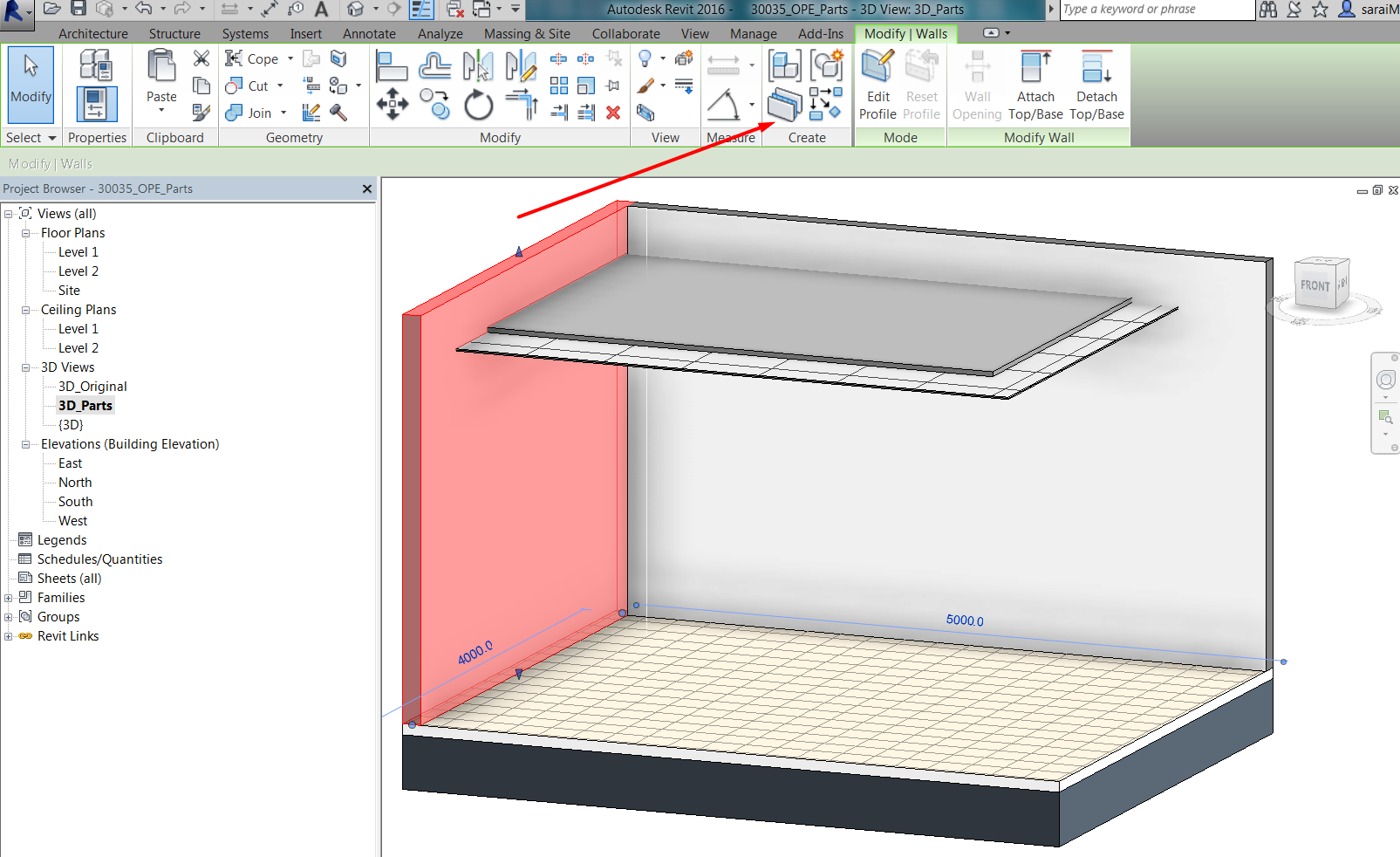
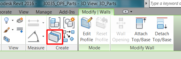
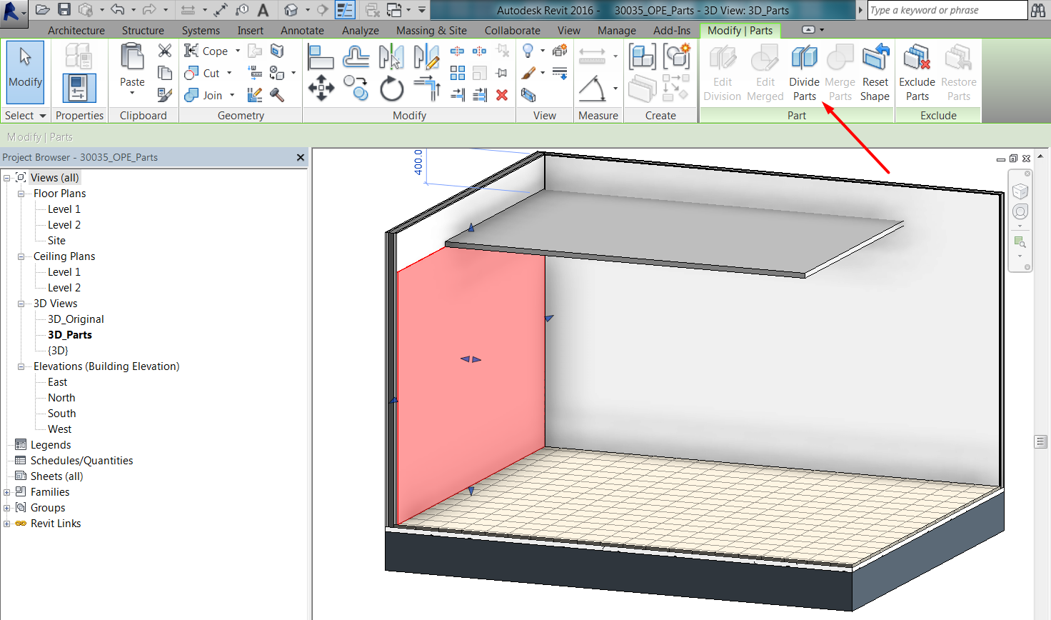
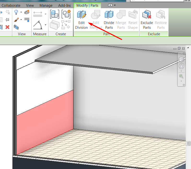
To generate parts user has to select the object to be edited, and select the Parts tool: Modify Tab > Create Panel > Parts:
For layered components, such as walls, floors, roofs, ceilings, etc., every layer in the composition of the element will be converted into a part. Original element will be preserved.
Part visualization
Before editing parts any further, user has to be aware of how parts are displayed in the model.
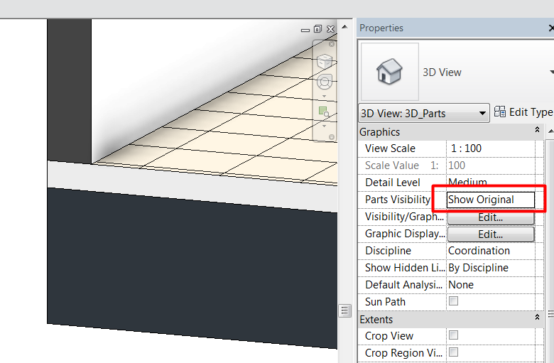
Visualization of parts is view-specific. Every view, plan, section, elevation or 3D, has an instance property called “Parts Visibility”, so user has to configure it in each view depending on what he wants to show :
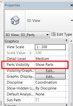
This property can be set to:
- Show original: it will display the original element, that as said, is preserved when creating parts.
- Show parts: view will display parts created from components.
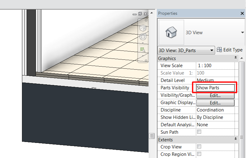
- Show both: view will display both original elements and generated parts. This kind of view is not adequate for documentation, but can be useful while working on model. User will have to use Tab key to properly select elements.
Objects that are parts belong to a special category: “Parts”. Original elements preserve their category, but parts are categorized as “Parts”, no matter which was the original category they come from.
This means that in views that show parts, they will be displayed according to their instances settings (material), but they will be override if in the Visibility/Graphics Overrides Menu any change is made to the Parts Category:
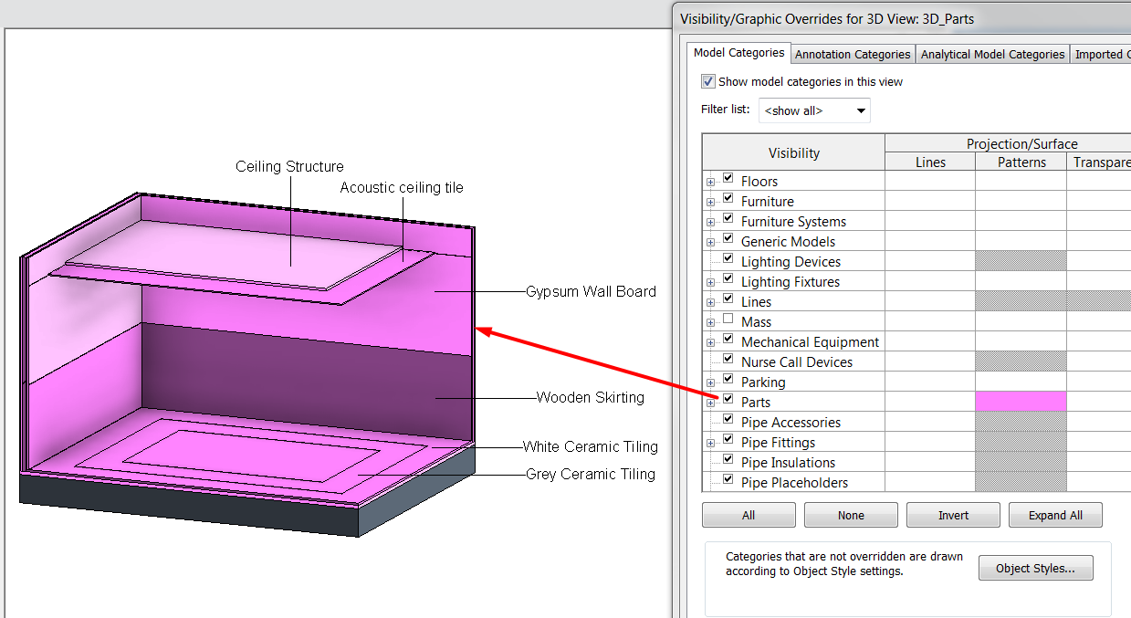
If the visibility option is unchecked for Parts Category, original components will be shown in that view.
Edit parts
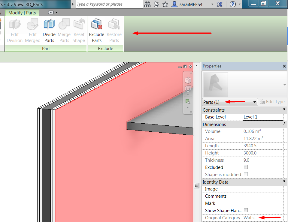
Once parts of components have been created, user will be able to select each part (layers in walls, ceilings, roofs, floors…) independently.
Element is categorized as “Part”, although it preserves the original category as element information, and a new set of tools are available for part edition.
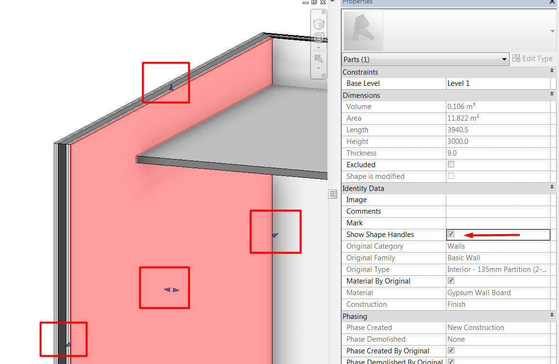
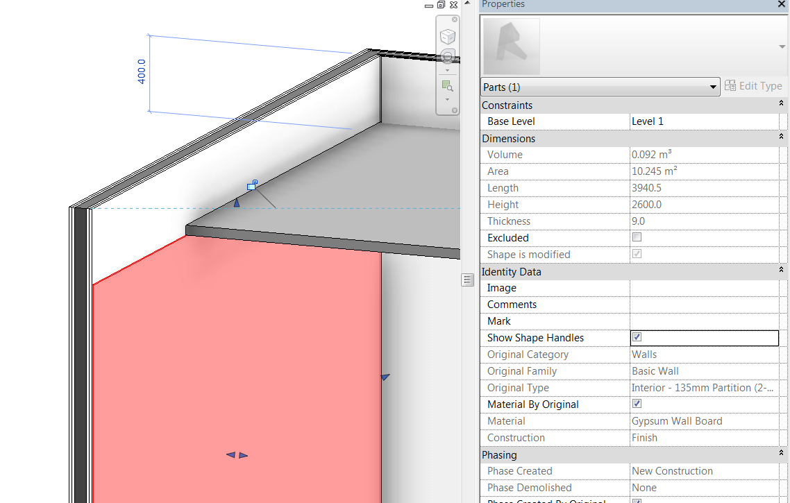
If we select a part, to change it we could:
- Show shape handles: to edit the part by dragging the shape handles grips on every side of the part. This allows the user to extend the part beyond the original limits, or change manually its thickness on the screen:
- Divide parts: we can divide parts into smaller pieces, making for every part any design that we want.
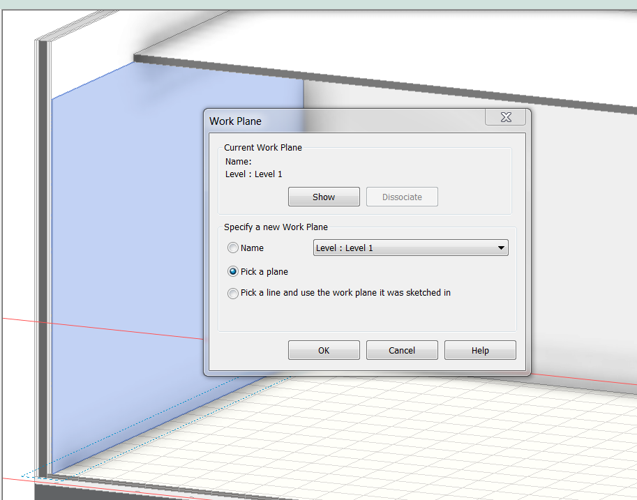
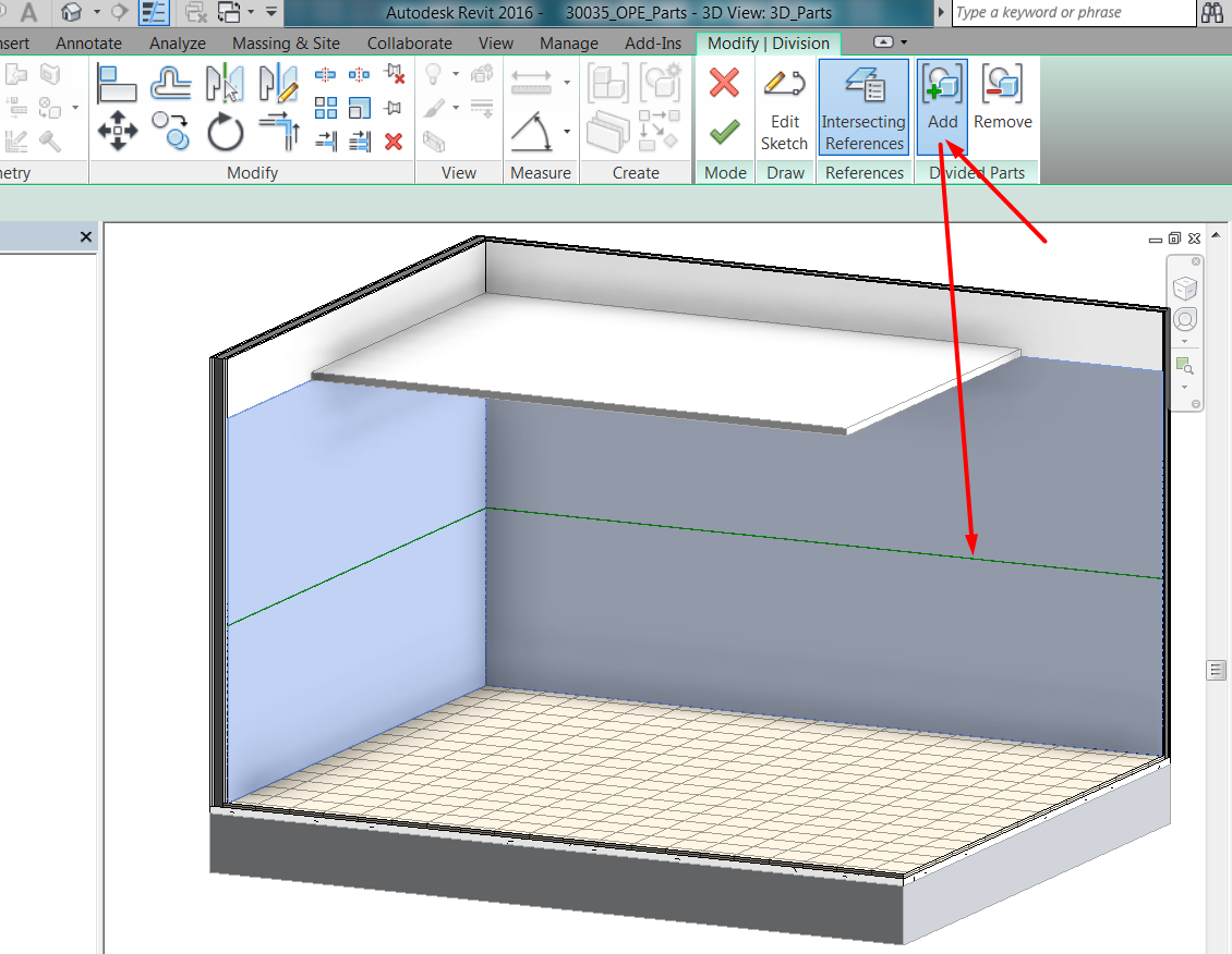
There are two ways of dividing a part into smaller parts. It can be done with a sketch, or by intersecting the element with reference elements (levels, grids, reference planes) that already exist in the model.
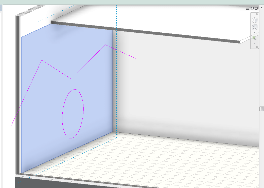
If user sketches the part division, he has to be careful with the position of the workplane, so that it matches the intention of the edition:
Then, the sketch to divide the part can go beyond the Part limits, or for closed loops inside them:
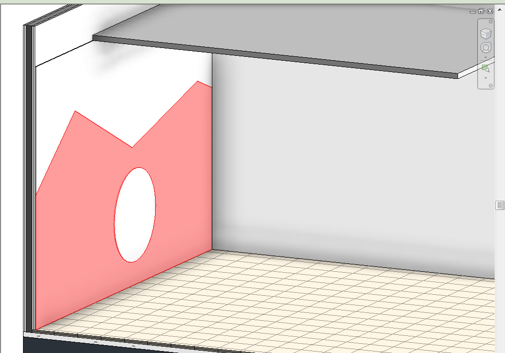
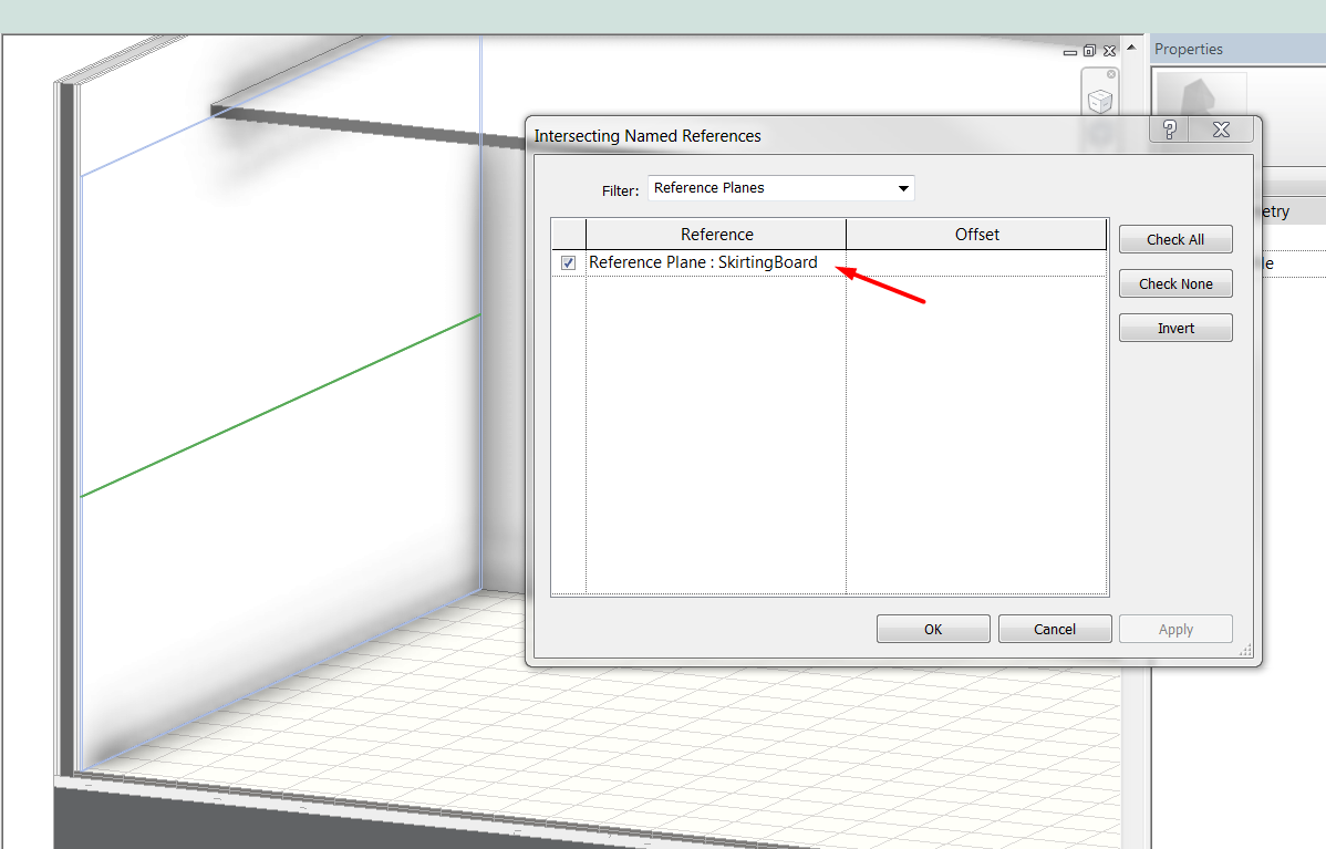
As said, user can divide the part with free form sketches, or using existing model references:
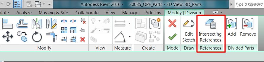
When a part division is created, it can be later edited, and other elements can be added to that division so that they are simultaneously affected by it. The elements that can be added to a division selection are those that have adjacent edges with the original divided element:
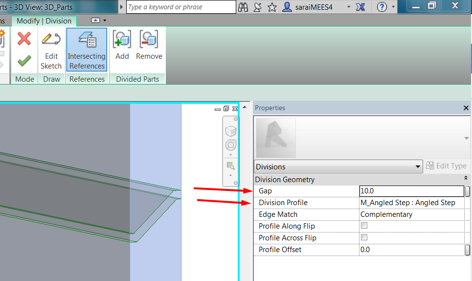
Notice that while editing the division, there are two options that can be interesting for the detailing: The gap of the division, and the profile used for it. If the gap is set to 0.0, divided parts will be adjacent, otherwise there will be a gap between them. Same with the profile, the division is straight if set to none, but can be customized:
- Merge Parts: if user selects two or more adjacent Parts (Parts that share a physical edge) and then click the Merge Parts button, they will be joined to create a single Part.
- Exclude Parts: This removes a Part. It is like deleting the Part, however, it can still be highlighted and restored if desired.
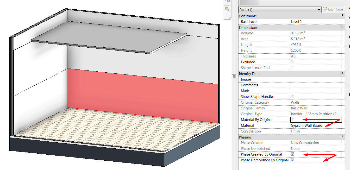
Beyond the geometrical edition, part material and phases can be made independent from the original material of the part, offering the possibility of a detailed customization of components in the model:
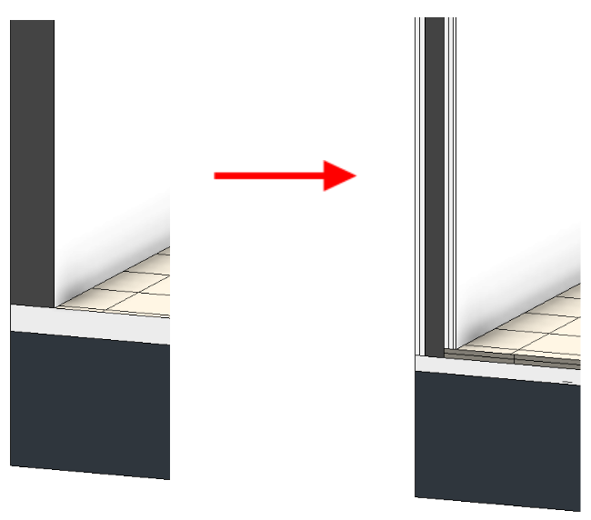
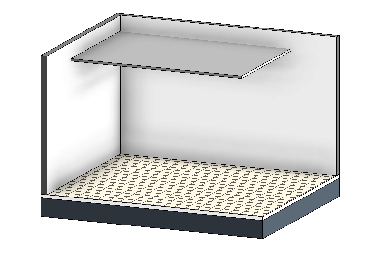
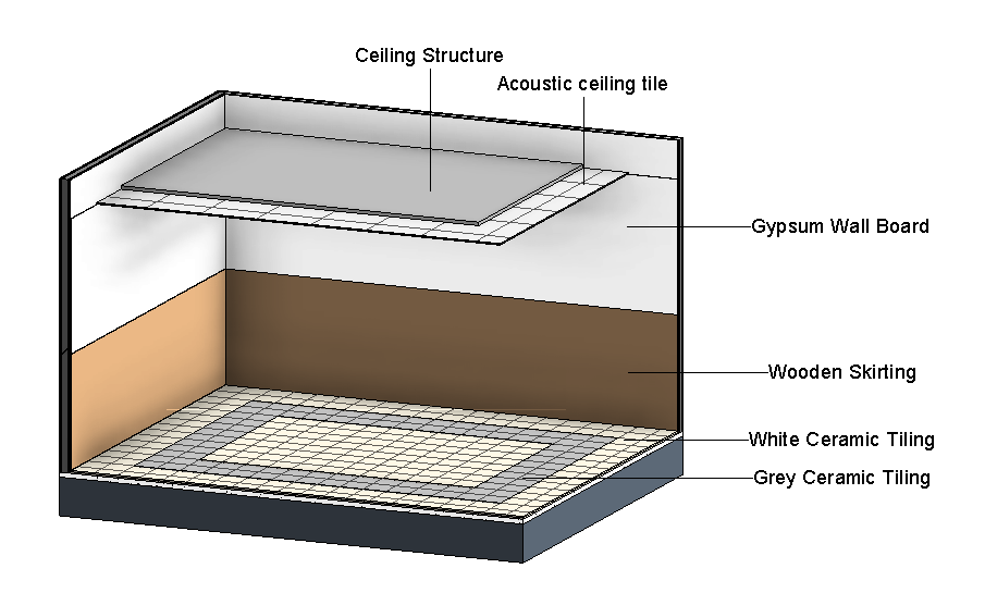
With the part tools we can develop further the models for construction or interior design, without having to modify radically the base of that models. Following two images are the same model, one image with original elements, the other showing created and edited parts:
Parts in links
As previously said, parts work through links.
This means that if we have a link loaded, we can select one element of the link and create parts from it, and work with them as if they were derived from a component directly placed in the model.
But the link will not be modified.
- Parts derived from elements in linked models work like any other part.
- Parts derived from elements in linked models will be visible although the link is unloaded.
- Parts derived from elements in linked models will be deleted if the link is deleted.
Schedule Parts
Scheduling parts is not different from scheduling other elements.
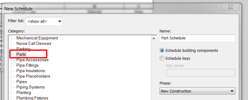
Just remember that when you want to schedule parts that are derived from other elements, they are no longer walls / floors / ceilings /… but they are categorized as Parts.
So, if we create a new Quantity or Material Take-Off Schedule, we will choose “Parts” category:
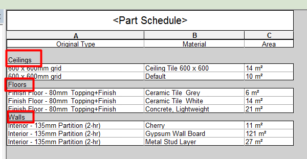
Elements keep record of their original category, and that can be displayed in Part Schedules.
Tips&Tricks
- Floor elements occur below the current Level (their thickness projects down instead of up). They have a special behavior when displaying in plans, because despite they are below the bottom plane of the view range (below the current level), they are shown in plan views. But parts do not have this special feature, so when you convert a floor into parts, remember to adjust view range lowering either the depth or the bottom plane, so that it includes floor parts and they are correctly displayed.
- Creating parts you can customize designs of project finishes, and adjust top and bottom limits of elements so that they fit better the construction logic.
Conclusion
Parts as assemblies are meant to help in construction documentation, but they can be suitable also for other tasks and workflows, such as interior/exterior finish detailing.
In particular, the use of parts can help to:
- Keep track of model authoring: the Architect can maintain ownership of the main model geometry and then the Interior Designer or the Contractor can use Parts to further articulate the finishes or construction modulation, without having to remodel the project.
- Finishes can be modeled, or detailed modeled in a rational way, rather than drafted, and that helps when it comes to quantifying the project.
- Parts can have their own Materials.
These are some examples where the use of Parts can be advantageous:
- Modulation of foundation retaining walls. They can be modeled first as a basic wall, and divided later into modules including even the customize joint.
- Division of a concrete slab in the pouring modules.
- Detailed design of finish floors/walls.
- Modulation of curved-shaped facades without using curtain walls.