
Electrical Families
Modeling and configuration in Revit
Electrical Families
Objectives
- Classifying an electrical and communication family.
- Hosting families properly.
- Creating types of symbology.
- Creating light sources.
- Understanding Connectors.
Prerequisites
- Users will be using Revit 2015 or later versions.
- The user should be familiar with real-life electrical solutions.
Description
This document explains the general procedure to produce high quality electrical Revit families, the steps explained cover what follows:
- Category Classification: Part Type, Use of Types.
- Hosting / Slope /Tilt.
- Geometry and clearance.
- Annotation Symbols.
- Light-source.
- Connectors: System Type, Number of Poles, Power Factor State, Load Classifications, Electrical Parameters, Utility and Connector description.
Procedure
Category Classification
Families must be ordered and organized correctly in the model. The first level in the Revit hierarchy is the Category. The program distinguishes family functions according to their Category. Categories change how families interact with the MEP model. Moreover, choosing a Category has an impact on native template parameters that will be available when working with those families.
Among others, following categories of electrical and communication devices related this document can be found in Revit MEP:
- Electrical Equipment
- Electrical Fixture
- Lighting Fixture
- Fire Alarm Devices
- Lighting Devices
- Telephone Devices
- Nurse Call Devices
- Communication Devices
- Data Devices
- Security Devices
Which correspond to the following real live equipments:
Equipment | Revit Category |
Electrical | Electrical Equipment |
Lighting Fixture | |
Electrical Devices | Electrical Fixture |
Lighting Devices | |
Other Devices | Communication Devices |
Fire Alarm Devices | |
Nurse Call Devices | |
Telephone Devices | |
Data Devices | |
Security Devices |
There is a category called “Specialty Equipment” that does not fall under the MEP Categories, so try not to use it when creating any electrical family.
Part Type in Families
The Part Type parameter provides additional sub-classification of a family category, and determines the behavior for the family.
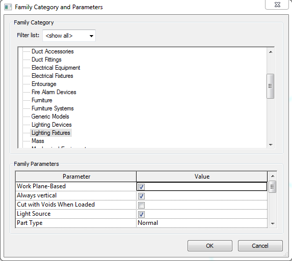
These options are available in the Family Category and Parameters Menu in the family environment:
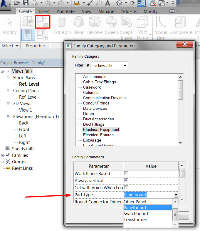
If a family category provides a Part Type parameter, the Part Type values available will depend on the family category. Regarding the categories above, they will be classified as follows:
Family Category | Part type associated |
Electrical Equipment | Transformer, Switchboard, Panelboard, Other panel, Equipment Switch |
Electrical Fixture, Lighting Devices, Nurse Call Devices, Security Devices, | Switch, Junction box, Normal |
Communication Fixtures, Data Devices, Fire Alarm Devices, Lighting Fixtures, Telephone Devices | Junction box, Normal |
When you are creating MEP families, you need to decide first which parameters are going to be used to determine the family definition. Additionally you have to decide which of those parameters will drive the different types within the family (Type parameters), and which ones will be instance parameters.
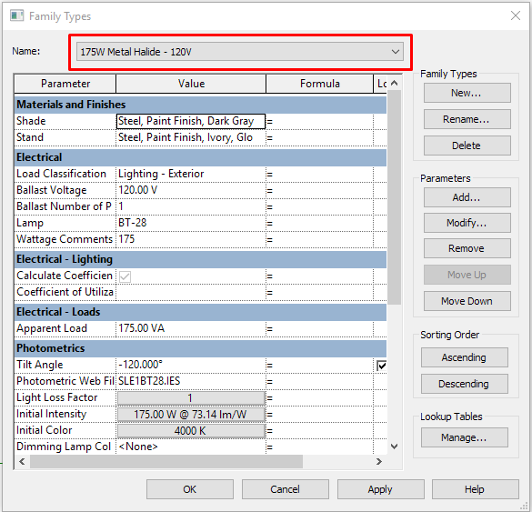
Because of the variety of families within the electrical section, we named the most common practices to define types: use parameters based on Dimensions; use parameters based on Equipment or Fixture Performance: this is the most common and most recommended; use parameters based on Number of Elements. (e.g. Number of lamps). This image shows the Lighting fixture types based on Performance: Wattage, Material and Voltage:
Hosting / Slope / Tilt
How the family will be hosted in your model is the first thing to consider when we start creating an electrical family.
Each hosting option determines how the fixture's geometry will be oriented in the family.
Non-hosted electrical Family
Usually non-hosted families are used when there are no architecture elements for hosting them, that is, MEP projects where the Architecture, Structure and Facilities models are totally independent.
The use of non-hosted families can lead to greater coordination work in later phases of the project because they do not adjust their position automatically when architectural or structural elements change.
But at the same time it is because of that independence that they are most of the times more suitable for modeling, because they do not rely on not controlled architectural or structural elements.
Aspects to consider with these families:
Insertion Point
As with any family you create, the insertion point is an important consideration when building the geometry of a lighting fixture. You can proceed in two different ways to create it:
The first one is to model the geometry in a reference plane that adjusts its location depending on the system Offset parameter value.
The second one is to create geometry with a fixed offset. If the family is correctly created, the fixed offset value will add to the system offset value, so be careful with that.
Slope / Tilt
One of the tasks we sometimes face is to adapt our family inclination to follow the slope of a surface such as a sloped ceiling.
It can be done in two ways:
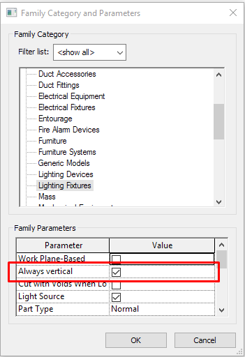
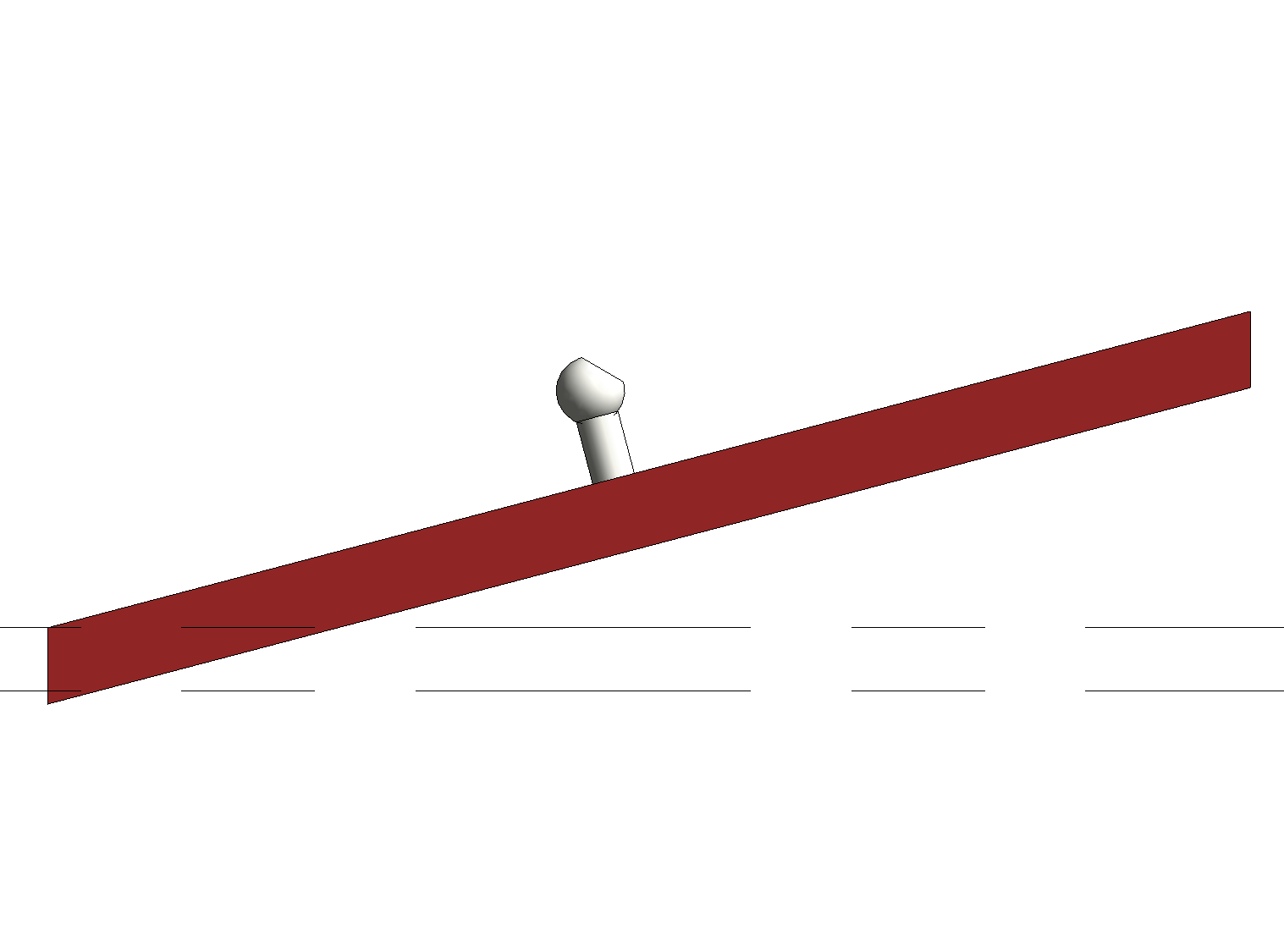
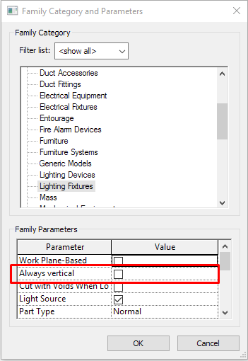
Within Family Category and Parameters, disable parameter family: “Always vertical”. In that case, elements will take the slope of their hosts if they are actually hosted on a floor, level (cannot be sloped), or surface.
Always vertical selected:
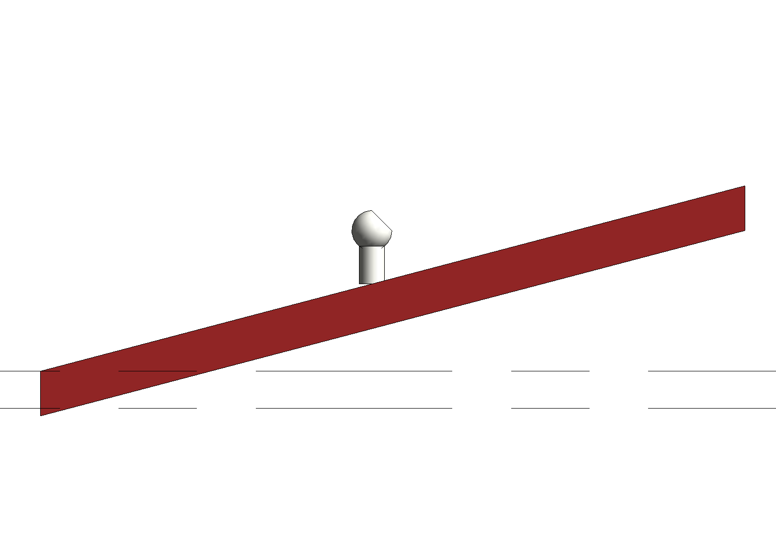
Always vertical non enabled:
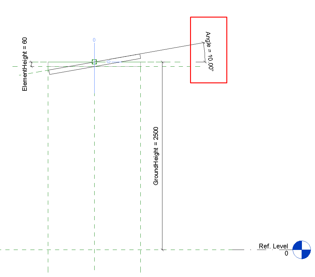
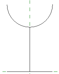
We can also create a sloped reference line in the family that can be controlled by an angle parameter, which can be modified later within the project.
This can be useful in some cases when we want to be free to rotate the object at any angle that does not depend on the surface that it is placed on.
In other cases, it might be a bit impractical to measure the specific angle of a surface any time we have to place an object.
Sloped Reference plane:
Hosted electrical Family
The family gets placed associated with its host. To have this type of family it is necessary to create them based on specific family templates or features. The different options are:
Families based on workplanes
In any family category you can activate the work plane based parameter in the Opening Family and Category Parameters menu:
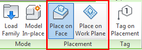
This means that when you place the family in the model you will have to select the placement option (face or work plane) and then choose the host of the family.
Face-hosted (ceiling/floor/roof/wall)
Creating face-hosted fixture families adds another level of coordination to your projects because the families move with their associated hosts. This keeps your fixtures at the correct elevations when ceiling heights change. Fixtures mounted to vertical host faces, such as walls, also move with changes to the vertical host locations.
To create a lighting fixture family that is face-hosted, you can use the Generic Model face based.rfa family template. Once you’ve opened it, you can change the category of the family.
Anyway, you have to be careful with hosted families because when host elements disappear or move we can have unexpected results with the hosted elements.
Geometry for Connectors and Clearance
One of the main features of MEP families are the connectors. Connectors enable the capability that MEP elements have to connect to each other, creating interconnected systems where calculations can happen.
Geometry for Connectors
Connectors in families can be placed using two methods:
Positioning them on one face of the family's existing geometry. In this case the connector will be placed and will remain at the center of that face. This means that what we control in the family with parameters is the position of the geometry that hosts the connector.
We can also associate the connector with a work plane within the family. When you associate a connector with a work plane, it can be moved along the surface of the plane and be controlled by parameters like any other elements.
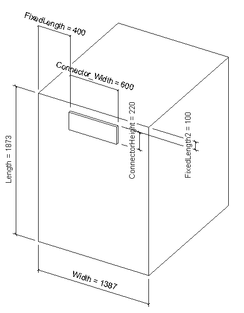
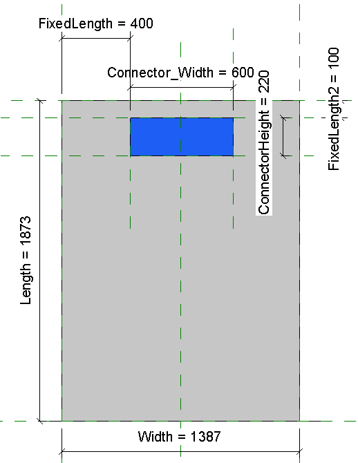
Clearance Spaces
We can create auxiliary, faux volumes to demark the clearance requirements around families.
Procedure
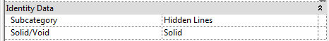
We create an extrusion with the shape and minimum dimensions established by the equipment manufacturer. To restrict the extrusion with parameters so that this clearance volume can be later adapted depends on the decision of the user or BIM manager.
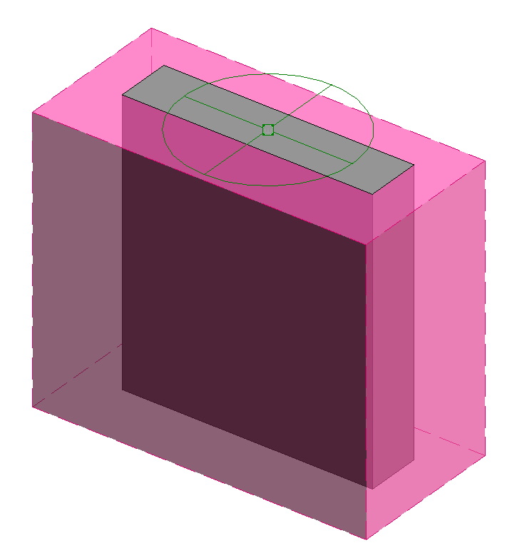
We apply visibility options to the reserve volume:
Apply a material and its properties, like color, transparency, etc ...
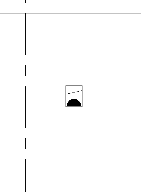
Apply a subcategory: For instance Hidden lines subcategory, or better create a new one named “Clearance”. This way we can control the visibility in views of the clearance volume independently from the rest of the geometry in the family.
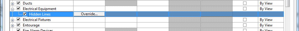
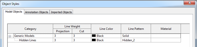
The subcategory has associated even a line pattern to the geometry’s plan view/representation.
Annotation Symbols
The symbolism in families can be incorporated directly by adding “Symbolic lines” to which we can associate a separate sub-category and visibility (yes/no parameter) options depending on the level of detail and how we want to play with symbols.
If we use this option, we will have to take into account that the resulting symbol will adjust according to the scale although they are symbolic lines. Dimensionally these elements will have model elements behavior. Also, if we just add symbolic lines we will have to make sure that they are also restricted so that they flex correctly as the family does.
That is why it is recommended to nest families to represent the annotation. There are two options to nest symbolic families depending on what we want to achieve:
- Nest a Detail component Family template: Detail items
- Nest an Annotation Symbol: Family template: Generic Annotations
Classification | Family Category | Change with Scale | Shows real drawings dimensions |
Annotation Symbols | Generic Annotations | NO | NO |
They have a printing size | |||
Detail Component* | Detail Item | YES | YES |
They have model dimensions | |||
Detail component:
Annotation symbol:
How to create and set up a nested Generic Annotation Family
Generic Annotation families are made up of detailed lines that form the symbol which represent the family.
We can create each symbol in a single family of Generic Annotation, or create a family that consists of different symbols that are driven by the type properties.
If we go for the second option we can afterwards associate each nested symbol type to each Electrical Fixture family type. We will see that in the following steps:
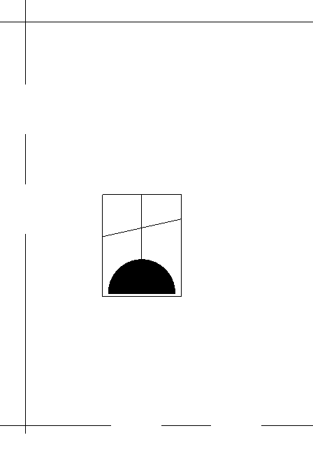
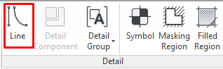
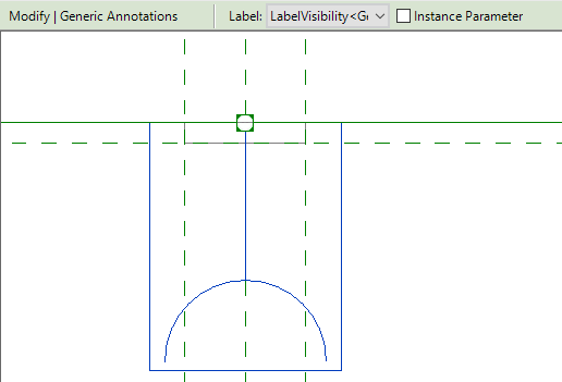
First we should create the shape of the first symbol that we want to represent with detailed lines. Create a new Generic Annotation Family > Create Tab > Line:
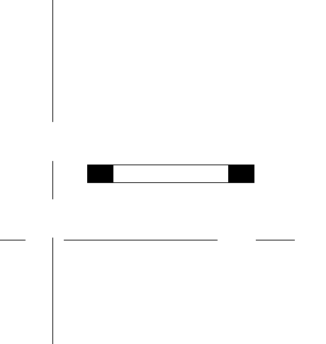
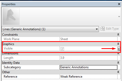
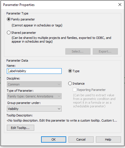
Second we should select the lines and filled regions that form one symbol, and nest their visibility parameter to a family visibility parameter:
To have a better control over the lines that we are creating, it is recommended to group the lines and filled regions that form each symbol, so that we can select them at once, because all symbols are going to be one on top of another:
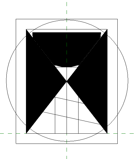
Once we have all the detail lines created and their visibility parameters linked to the family parameters, we create symbol types within the family, and in each type, we enable the visibility of the corresponding detail, and hide the rest of them:
Type 1:
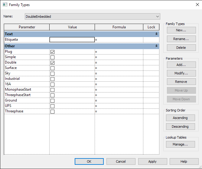
Type 2:
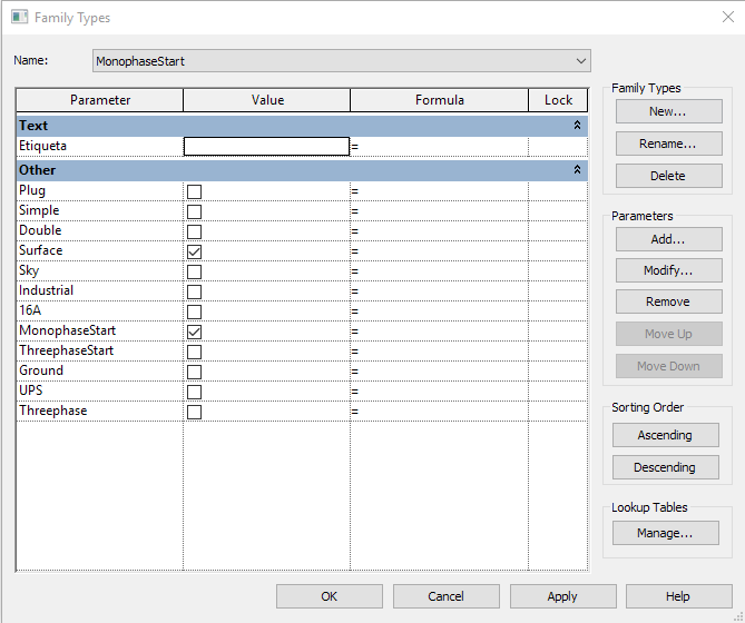
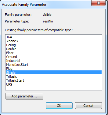
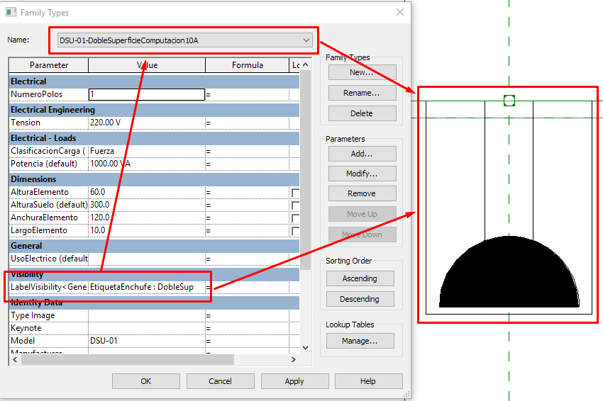
Then we save and name correctly the Symbol Family, we create/open the electrical family which will hold the symbol family, we load the symbol family into the electrical model family, and we place the symbol family at the desired location in the electrical model family. Then select the annotation symbol and apply a type parameter: Generic Annotation in "Label" parameter.
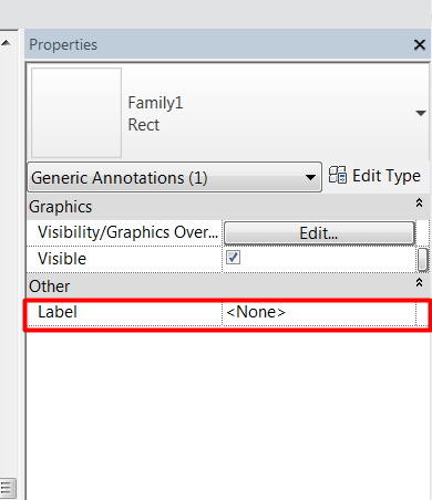
In the “Value” column of the new parameter we associate the symbol type to each family type created within the electrical fixture family.
That way whenever you choose an electrical family type, the corresponding annotation changes within the family and therefore, the desired symbol is displayed.
Family type 1:
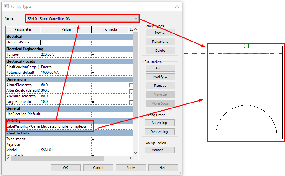
Family type 2:
Text and Labels
As said previously to create a symbol you can do it by directly using symbolic lines in an electrical model family, or you can use a nested generic annotation family.
When we want to insert a symbol that includes a Text (or a parametric text called Label), there is only one option to proceed and be successful: use a nested generic annotation family.
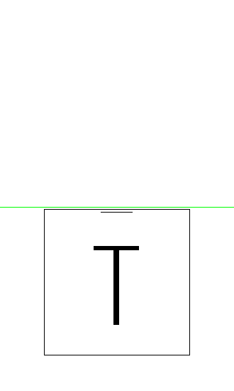
When we place a text object into your family, it is important to consider the family orientation in the project. It could have different orientations or even be mirrored.
To avoid that, there is an option in the Family Category and Parameters menu, called “Keep Text Readable” that allows us to fix the orientation of the text in order to read it always from the left to right and bottom to top, no matter how the family is actually oriented:
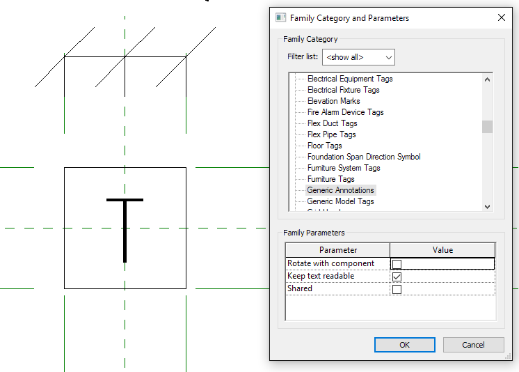
Example:
How to create and set up a nested Detail Item Family
Nested Detail Items work exactly the same as nested Generic Annotation families. We will follow the same procedure to use them, just keeping in mind that their dimensions are model related unlike those in generic annotations that are print related.
Light-Source
Lighting Fixture families require a light source if they are going to be used for rendering or lighting calculations. A light source is a unique feature of a lighting fixture family that acts as the part that emits light. It is possible to have a fixture family with multiple light sources, such as track lights or a chandelier. This requires creating a separate family that defines the light source, and then nesting it into your fixture family.
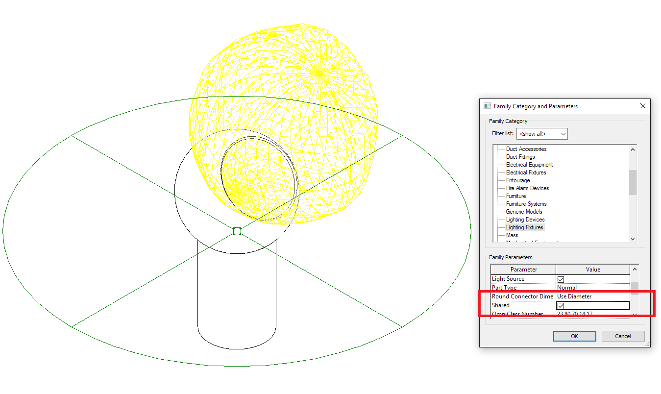
The nested family must be shared to act as an effective light source.
Make a family a shared family
You can set a family to be shared by selecting the Shared box in the Family Category And Parameters dialog box.
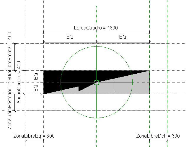
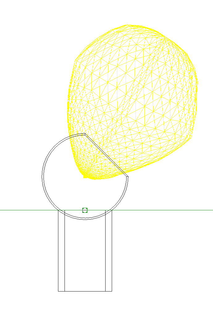
Location
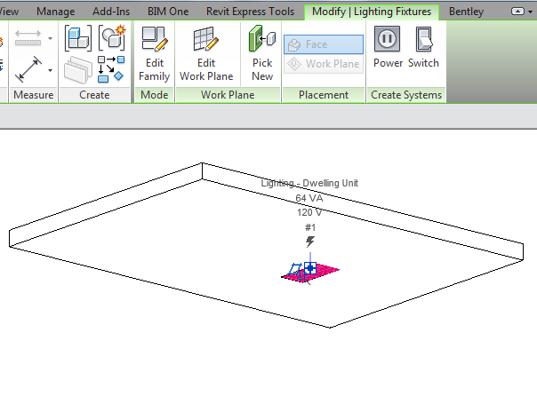
Light source objects have axes that allow you to align and lock them, to the fixture geometry or to a reference plane. The light source can be located on the face of your fixture geometry, or it can be located within a void inside the geometry for a more realistic representation of the fixture.
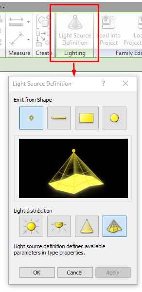
Light Source Definitions and Parameters
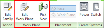
You can define the shape and distribution pattern of the light source, click on the Light Source Definition button on the Lighting panel of the contextual tab, it appears when you select the light source:
For more information about Light Source Definitions and parameters, see The lighting Analysis guideline.
Connectors
The connectors allow to create logical systems within the model, that is, create a relationship between parametric elements which can draw calculations and technical information of the electrical system.
Connectors, especially in Revit, are key in the usefulness of an MEP component because they define the usability and calculations associated with the object, and set the uses and information the engineer will be able to work with.
The connectors that you add to electrical equipment, devices and fixtures families will be (in most cases) electrical connectors:
Electrical connectors are classified depending on the system of which they will be part:
- Power - Balanced
- Power - Unbalanced
- Data
- Telephone
- Security
- Fire Alarm
- Nurse Call
- Controls
If the project required a physical connection between the electrical families, or between electrical families and panels, we could incorporate Conduits and Cable Trays connectors in the family, and of course control their dimensions with parameters.
Parameters
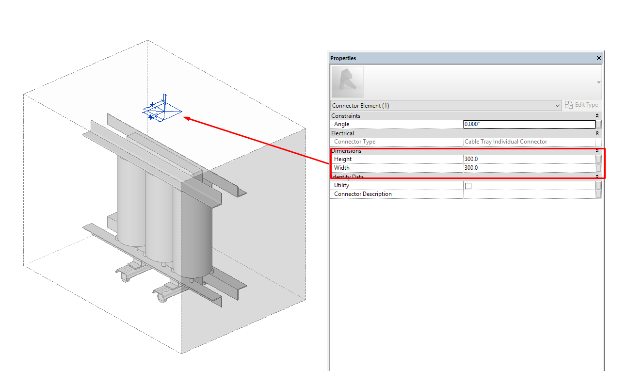
Existing parameters in the connectors are shown as follows:
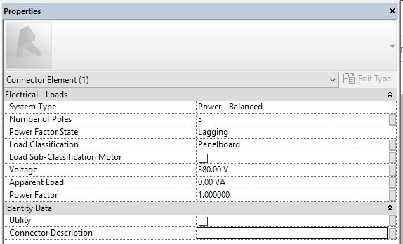
Sample shows the parameters of an electrical connector.
As for parameterization, connectors are like any other elements in families.
We could set some values for the connector properties and they will remain fixed in the family, or we can associate the connector properties to family parameters so that we can change them depending on the settings of each type or instance of the family.
Some connector parameters cannot be parameterised, they are fixed in families and if we want to change them we should create a new family with new properties for the connector:
- System type: switches between the different types of systems available in the project.
- Power factor State: The ratio of the real power flowing to the load to the apparent power in the circuit. Lagging or Leading.
Other connector properties can be normally linked to family parameters:
Number of poles: they relate to the physical slot locations on a panel.
Load Classification: it allows to classify each type of electrical load connected to a panel.
Load Sub-Classification Motor: add the ability to have a 2nd "nested" demand factor.
Voltage: specified the electrical tension.
Apparent load: is the product of voltage and current.
Power Factor: the ratio of the real power flowing divided by the apparent power in the circuit.
Utility: family Utility Description.
Connector description: text parameter to connector description.
Tips & Tricks
- Using Non-hosted Families. It allows us to individualize our model and make it independent. They are useful in areas that do not have a ceiling or for freestanding lights. They can be given an offset to the level at which they are inserted to show them above the floor. It is necessary to have a greater degree of coordination.
- Not to use the Specialty equipment Category. Specialty Equipment does not belong to MEP Family Categories. When a mechanical, plumbing and electrical discipline template is activated, the graphics display of this family will be totally different from the rest of the project.
Conclusion
When developing MEP families, it’s important to keep in mind the family classification: families must be organized correctly in the model, considering that the first level in the Revit hierarchy is the Category.
This document compares and evaluates hosting options for electrical fixtures / families. Each hosting option determines how the geometry of the fixture will be oriented in the model and if it needs a host to be placed.
This document also explains how to create Symbolic Annotations and Detail components for electrical families, and the differences between their behavior.
It also explains Connectors and how to install them within a Family. The connectors allow to create logical systems within the model, that is, create a relationship between parametric elements which can draw calculations and technical information of the electrical system.
Associated Files
- 30035_Custom and Current Library families
- Guideline - Modelling Families
- Guideline - Nested Families
- Guideline - Complex Families
- Guideline - Lighting Analysis
Hello,
this is a great article. It helped me so much. I have one question.
There are a lot of Part types in Revit. Most of the electrical categories include Normal and Junction box Part type. Is there any difference between them? (calculation or visibility)
Thank you
George
Hi George,
Good question
Whenever I have any doubt with the part type application I check how Autodesk implement them in Revit OOTB families, unfortunately I haven’t found anyone with the Junction box part type applied. We have to seek more in order to find information from the use of this particular part type.
From Autodesk documentation, you can use this part type when you’re documenting wires in your project for making multiple branches, check this link:
“Junction Box: Wire management devices through which wiring is generally drawn through the device. As indicated in the image, the automatically generated wiring branches through the junction box.”
I usually don’t document wires by the Revit way, so I don’t use it 🙂
If you find any other intelligent way to use it, please share it with me!
Thanks for your comment!
Regards
Really happy to say, very interesting to read your post to bim clash detection services I will never stop myself from saying anything about this. You are doing a great job. Keep going.
Hi, yup this piece of writing is in fact good and I have learned lot of things from it
concerning blogging. thanks.
I have recently been developing a series of Devise Families. I am starting with a Generic Model with both Workplane based and Always Vertical on. Elements at vertical linked surfaces are placed by face and all are associated to their corresponding Level with both instance offsets at 0. Each Family has a Shared Type Parameter for mounting height including elements along horizontal surfaces. Is this a good workflow?
Hi Eric,
It depends on the type of device you are modelling and the type of surface you are going to use for its placement. There is no single criterion for device modelling. For MEP families it is usually useful to start the family modelling using the Autodesk electrical device families in the OOTB libraries as a reference and make changes to geomerty and parameters to match your requirements.
Hope it helps!
This is very very useful article