

Lighting Analysis
Operation in Revit
Lighting Analysis - Operation in Revit
Objectives
- To know what are the main physical concepts we are going to manage.
- How elements are related to light inside Revit.
- To meet light analysis that we can perform in Revit.
- To understand what kind of information we can take off from Revit.
Prerequisites
- User has internet connection.
- User will be using Revit 2015 or newer.
- User has basic knowledge about general light and sun physic principles.
- In manage.autodesk.com you have to check that with your account you can access to Green Building Studio. If you never have spent Autodesk Revit Cloud credits you should have enough credits for renders that we’re going to perform in this class
Description


This guideline explains how to perform Lighting analysis based on Revit models, covering the material properties and settings, light sources and their configuration (both natural light and lighting fixtures), lighting analysis+auxiliary tool, camera placement and use of spaces.
Procedure
Short introduction
Revit allows you to model and study lights in several ways. First of all we have to understand important light metrics we are going to use.
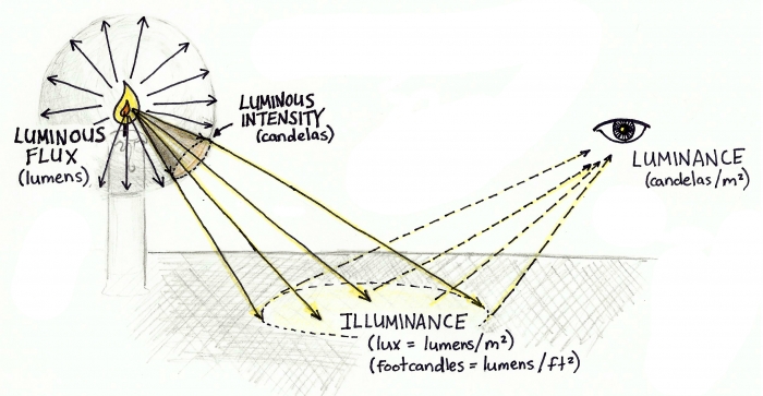
Lumen describes total emitted visible light from a source. Which is called sometimes as luminous flux or luminous power (remember that total power is expressed in Watts).
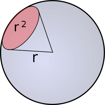
Candelas are luminous power per unit solid angle emitted by a point light source in a particular direction. Candelas are measured as if light was enclosed in an imaginary sphere. This is why we use solid angle to measure it. Solid angles are measured in stereoradians, a dimensionless unit which is described by images below:
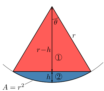
When modelling lighting within Revit these properties are inside light sources you use.
Illuminance is light falling on a surface. It is measured in lux (lumen/m²) This is an important metric for visual comfort optimizations. This does not depends on the material properties of the surface being illuminated, but depends on the materials properties surfaces around it.
Luminance is light reflected by a surface. Luminance is useful to study visual quality of a space, but not for studying light quantity. A luminance analysis, which also is made with the rendering tool, is good to describe if light is properly distributed, or to identify glare which are abrupt changes in near elements light emission, but not for determining if a space receives enough light for its intended use. We can do illuminance and luminance simulations (Lighting analysis) within Revit models with the rendering tool in a proper setup.
The data from an intelligent lighting model can be used for analysis and can aid in design decisions. They can also be used to develop cool images for presentations by generating realistic light in renderings.
We are going to work with Revit models of the Audubon Center in Columbus, Ohio.
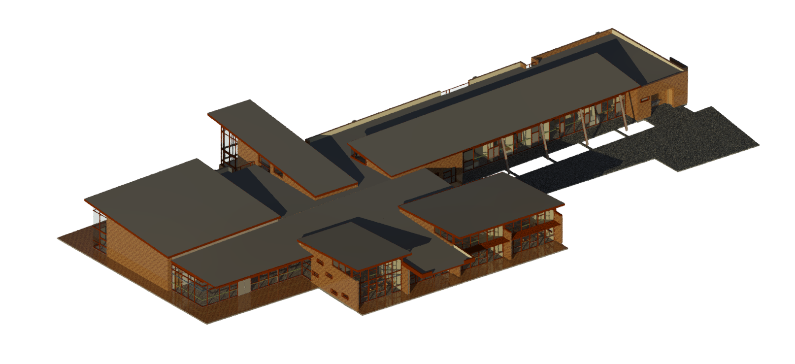
http://www.archdaily.com/148800/grange-insurance-audubon-center-designgroup
Material properties
The only important properties that we want to control to obtain accurate illuminance analysis is visual transmittance, or TVis in glass elements, and reflectivity of opaque materials that are in interior finishes (obviously it’s unuseful to change not visible elements’ properties). We can configure them by changing their material appearance. How can we change TVis? Go straight to the Appearance tab in material configuration. This tab is used to determine the physical properties of the materials used in the rendering.
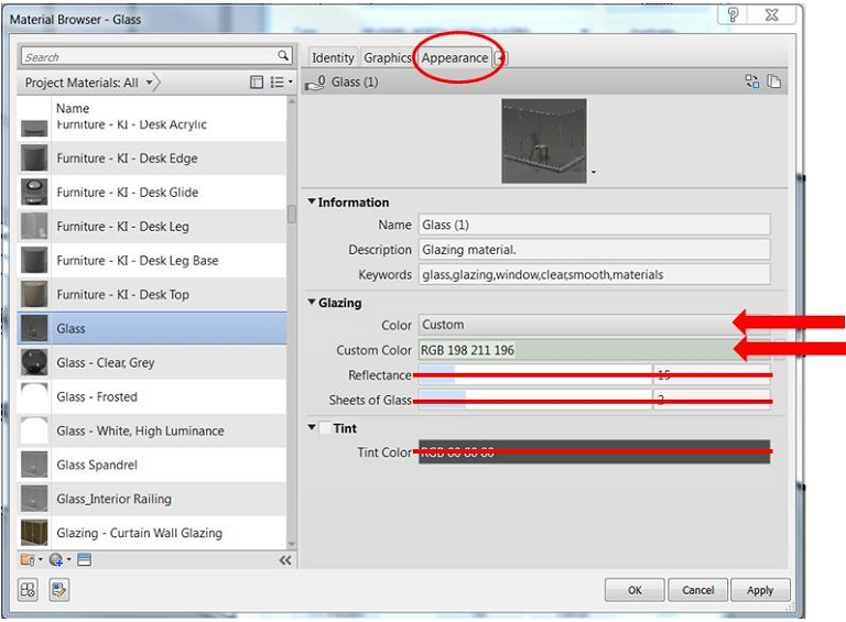
From the Appearance tab, the only settings used in the illuminance renderings are the Color field under Glazing. The Reflectance is NOT used for the illuminance rendering. Instead 360 Rendering uses a pre-defined value of ~4%. But how can we express a TVis only with color properties? This Chart will help us:

To use this chart:
- Determine the thickness of the window pane geometry in your Revit model, and the number of panes modeled (single, dual, etc.)- this is the ROW.
- Determine the TVis value you'd like to simulate - this is the COLUMN.
- Set the "color" of the glass material in your Revit family to have RGB values that are each equal to the number in the CELL (R=G=B) you've identified (high numbers are more transparent; low numbers are more opaque) For instance a TVis of 70%, you would specify R50, G50, B50.
For opaque materials on the Appearance Tab, the RGB Color settings within the Generic panel determine the reflectivity (%) of the material, based on the following formula:
(0.2126 R + 0.7152 G + 0.0722 B) / 255
If all other attributes in the Appearance tab are unchecked, the material will have a matte finish, with only diffuse reflectivity (not shiny/ specular).
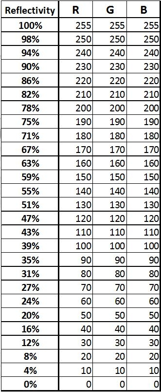
If an Image is selected, the average colors of the picture determine the basic material reflectivity due to Color in percent, by the formula: (0.2126 R + 0.7152 G + 0.0722 B) / 255 for each color in the picture.
It is also possible to simulate specular materials by selecting “Glossiness” and changing the settings there. This glossiness is specular reflectivity. Every other material property effects work in visual properties as you would visually expect.
Light sources in Revit
General settings
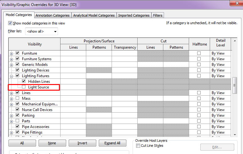
If we want to manage our light sources inside our project in 3D or floor plans for the view’s visual style, use Shaded to see how the light hits a wall or other surface. Remember to activate them in VV.
Skylight, Natural Light
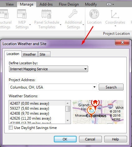
Project Location is crucial when we’re going to perform any kind of analysis that is related to the sun. Remember:
We don’t have to master sun concepts such as equinox, solstice, analemma, azimuth, altitude… Because Revit UI is user friendly enough, but it’s recommended. I’m not going to enter through these ones.
As rules of thumb: Equinox describes average conditions and Solstices describes extreme conditions. It’s recommended to model surrounding buildings in order to have best results.
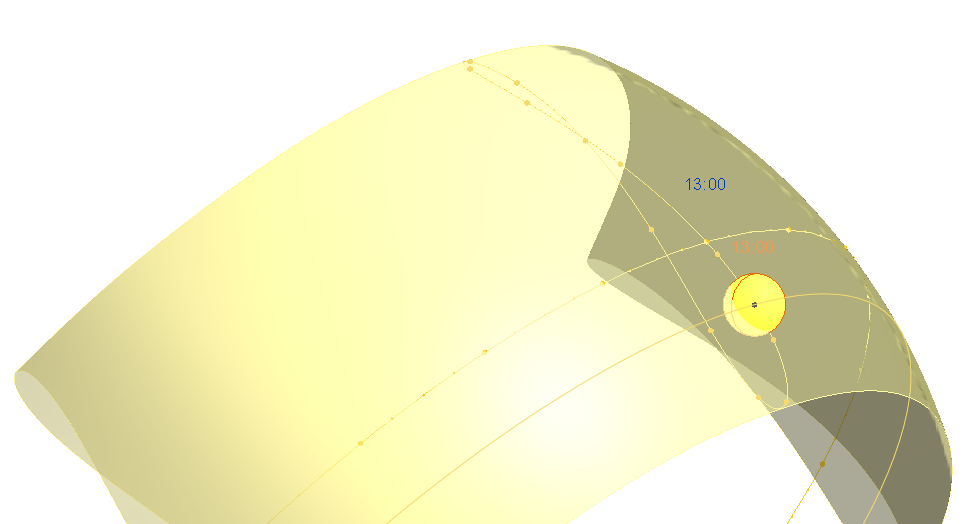
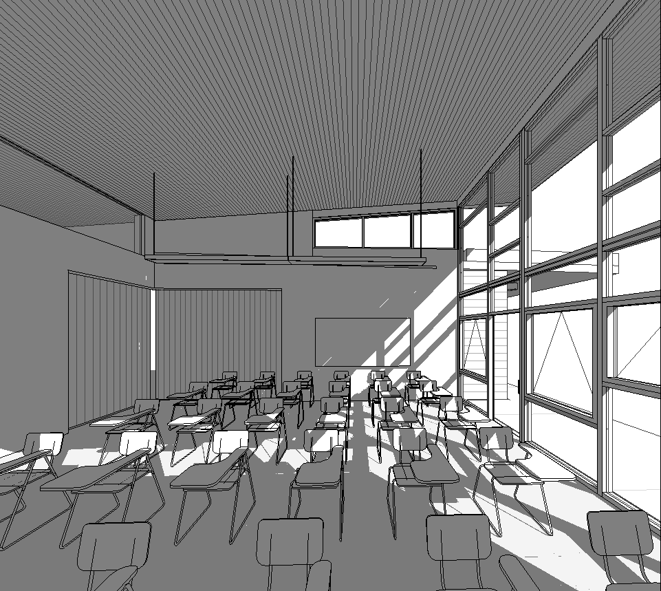
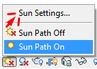
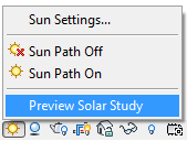
Remember that sun path can be activated from this icon which is just below view’s canvas. Sun settings are important to make solar studies. Another property to be activated is shadows, they are beside sun settings.


For these purposes we should go through the sun settings.
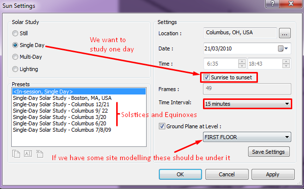
We are going to make an average one-day solar study and to export it. I prefer to call it shade study:
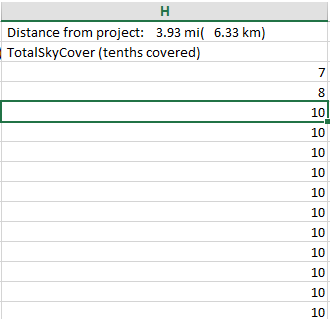
Sometimes we have to define sky conditions in render settings, it depends on what you want to get, but is better to do Daylight analysis with overcast skies which is the worst condition for daylighting. Although you can check your location skycover in Green Building Studio weather data (this process is explained later in Lighting analysis.Settings).
When we have configured properly sun settings, a new tool arrives! Preview Solar Study:
With this tool we can now export an animation from my simulation. Revit>Export>ImagesandAnimations>SolarStudy
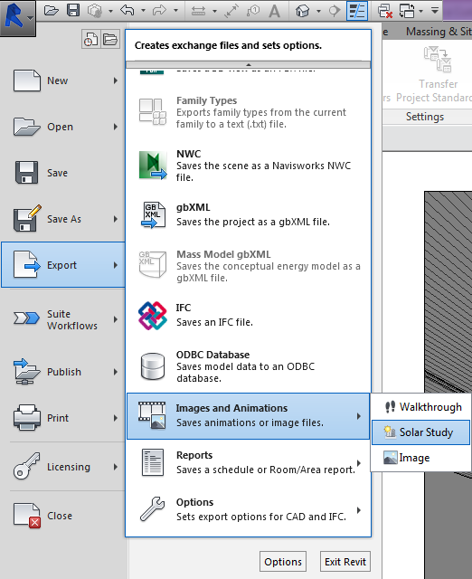
It exports an AVI file. That we can reproduce for example with VLC media player. My recommendation is to export it from a Shaded view with smooth lines with anti-aliasing and ambient shadows activated, uncompressed. It goes pretty fast and it’s descriptive enough.
As reference of what are our sky lighting conditions we can take outdoor light levels from EngineeringToolbox.com
Condition | Illumination | |
(ftcd) | (lux) | |
Sunlight | 10000 | 107527 |
Full Daylight | 1000 | 10752 |
Overcast Day | 100 | 1075 |
Very Dark Day | 10 | 107 |
Twilight | 1 | 10.8 |
Deep Twilight | 0.1 | 1.08 |
Full Moon | 0.01 | 0.108 |
Quarter Moon | 0.001 | 0.0108 |
Starlight | 0.0001 | 0.0011 |
Overcast Night | 0.00001 | 0.0001 |
Lighting fixtures: light bulbs
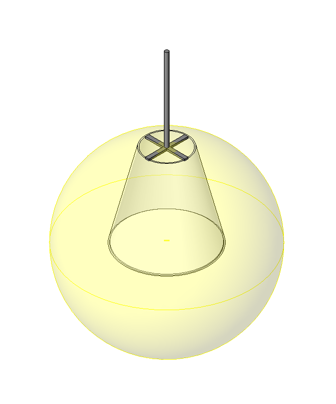
When you create a lighting fixture you find the possibility of creating its Light source. Position of this light source is responsibility of the lighting fixture modeller. It has to be correctly placed if we want to handle them properly inside a project.
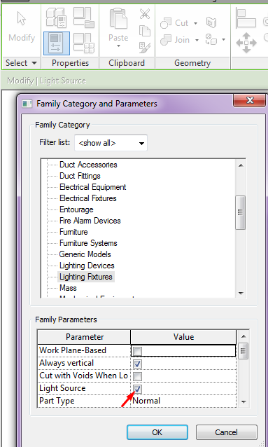
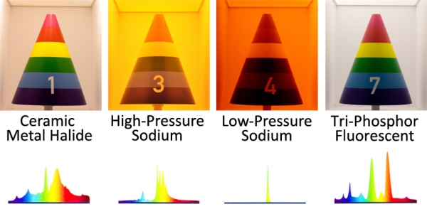
This light source could be modeled in several ways by default emission and distribution, or maybe you want to load a photometric web file (.ies file). For accurate lighting analysis this is recommended.
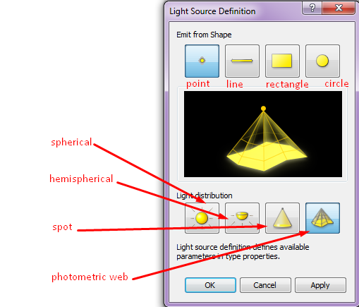
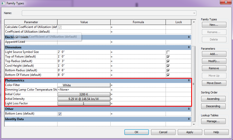
When we create a light source some new type parameters related to photometrics appears in my family.
If we have configured our light source as a photometric web file we can find in lighting fixtures type properties a parameter to path the photometric web file desired.
Here I lend you short descriptions about photometrics parameters.
Spot Tilt Angle | The angle to tilt the light source to direct its light. Enter a value between 0 and 160. Only in Spot or Photometric Web. |
Spot Field Angle | The angle at which the light intensity reaches 10% of the peak intensity. Enter a value between 0 and 160. Only in Spot. |
Spot Beam Angle | The angle at which the light intensity reaches 50% of the peak intensity. Only in Spot. |
Light Loss Factor | A value used to calculate the amount of light lost (or gained) due to environmental factors, such as dust and ambient temperature. It displays a dialog box. |
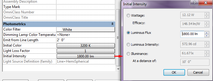
Initial Intensity | Brightness of the light before environmental factors reduce or change the quality of the light. It displays a dialog box where I can define some crucial metrics for Lighting analysis purposes. |
Initial Color | The color of the light source before it is affected by color filters and environmental factors. It displays a dialog box. |
Emit from Circle/Rectangle/Line Diameter/Width/Length | The dimensions of the light source that emits light in a rendered image. |
Emit Shape Visible in Rendering | Select this option to make the shape of the light visible as a self-luminous surface (glow) when the camera (of the 3D view) is aimed directly at the light source. This parameter is available when the Emit from Shape setting is Rectangle or Circle. In addition to setting this parameter, when defining render settings, you must select the Soft Shadows option on the Render Quality Settings dialog. Tip: If the Emit from Shape setting is Point or Line, the light source does not display a self-luminous surface in rendered images. To see the light source in rendered images, use a thin rectangle shape or a small circle shape instead. |
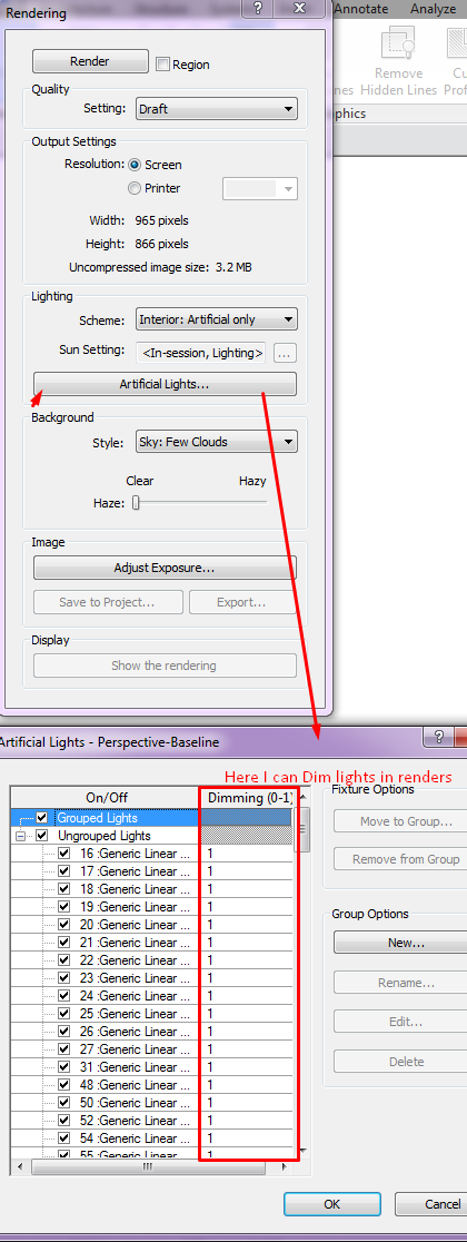
Dimming Lamp Color Temperature Shift | Specify whether the color and intensity of a dimmed light source change based on predefined curves. For example, incandescent lights typically become more yellow when dimmed. Select Incandescent Lamp Curve or none. To see the effect of this parameter, you must dim lights in the building model. |
Color Filter | Color used to change the light emitted from the light source. |
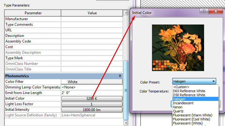
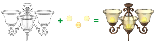
We can create families with multiple light sources with nested families. We use host geometry as my main family and we embed lighting fixtures with only light source inside.
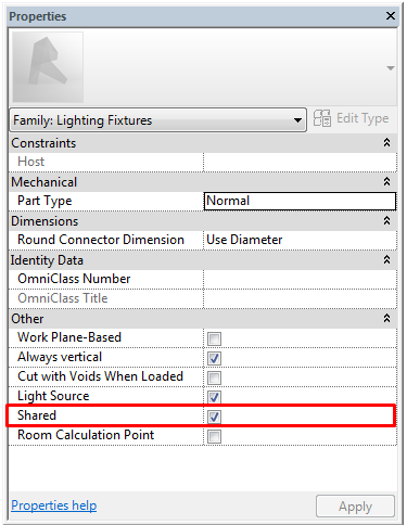
You have to activate shared property from properties if you want to control your light sources independently in the host family.
Lighting Analysis
Short introduction
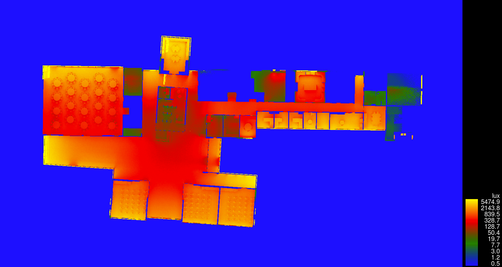
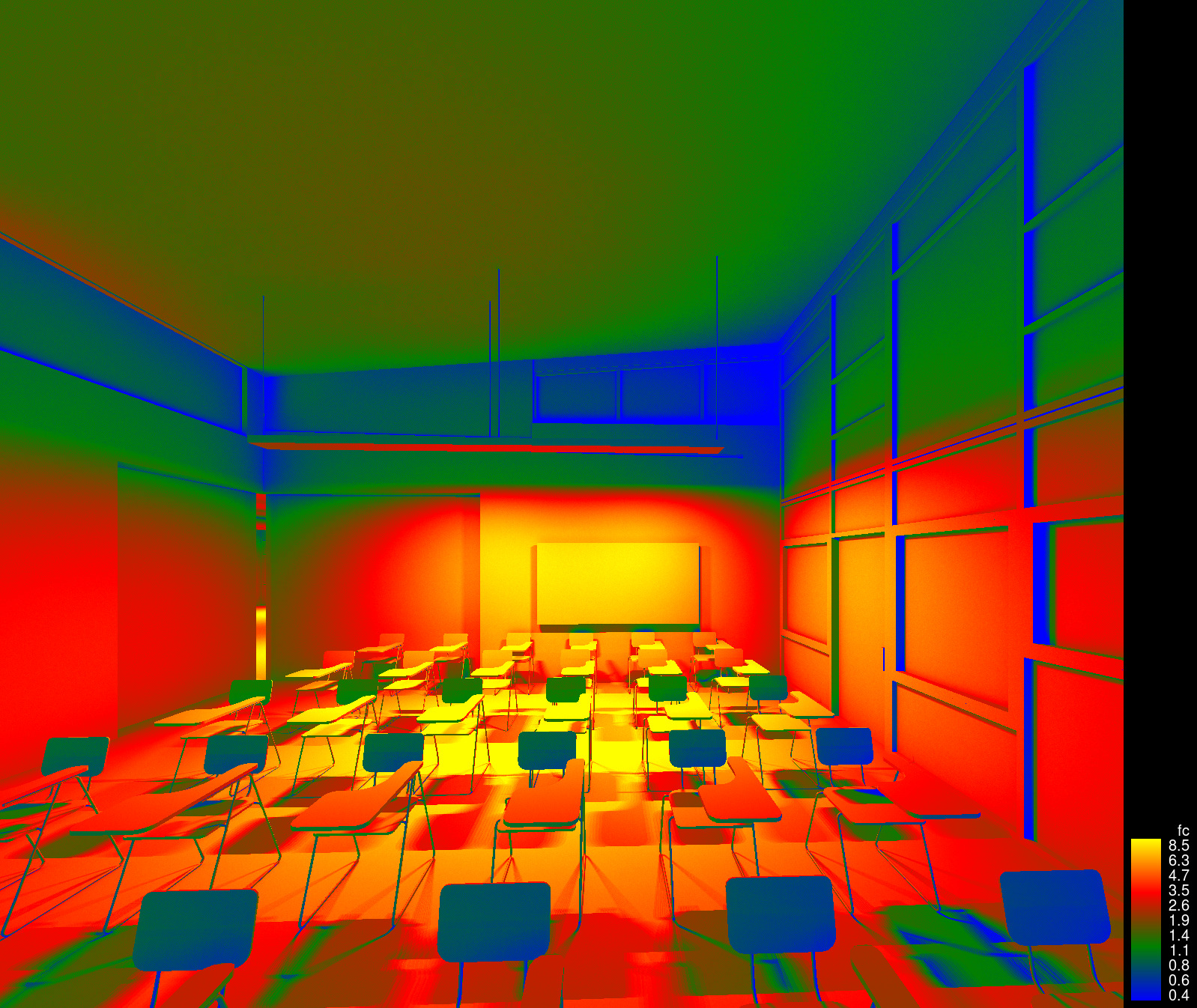
Within Revit we can perform Illuminance lighting analysis. Considering only daylighting like in the image above or only artificial lights like in the image below.
This analysis has to be done in 3D views and they respond to particular render properties that are defined in that view.
When we change render properties from a view we change them only in the view we are, this is crucial because it is true for cloud rendering tools too.
The difference between lighting configuration or daylighting configuration is the lighting scheme we use (see picture below). Illuminance analysis could be performed in artificial lights only, sun only or artificial + sun. We can access to the rendering properties of the view in View properties dialog box or through View tab.
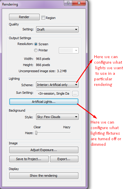
In our example we are not going to touch this, it’s configured for daylighting analysis purposes. But if we want to go through artificial lighting renderings we have to fight with exposure.
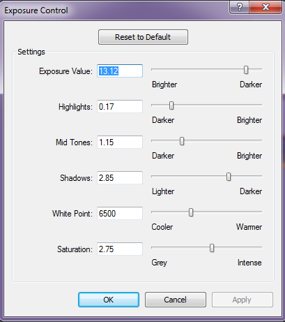
When you have done the render image you can touch this exposure settings freely. Image is no going to be rendered again and again at every step you make. Make a fast render in any view and play with it!
Settings
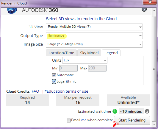
So we’re going to do some Cloud rendering from the View tab!
For our file use the following settings:
- Render All 3D Views (this will render all 7 3D views)
- Output Type = Illuminance
- Image Size = Large
- Set Date to 2016-09-21*
Equinoxes are good indicator of average conditions
- Set Time to 13:00
- From Sky Model roll down select CIE Overcast Sky**
Worst day scenario conditions:
- DNI = 746; DHI = 90
DNI = Direct Normal Irradiance [Input] - The terrestrial solar irradiance received per unit area of a surface that is normal to the sun’s position.
DHI = Diffuse Horizontal Irradiance [Input] - The terrestrial solar irradiance received by a horizontal surface which has been scattered or diffused by the atmosphere. It is the component of global horizontal irradiance which does not come from the beam of the sun.
You can find valid values for direct normal and diffuse horizontal irradiance values from the weather files that are built-into Autodesk Green Building Studio. Follow these steps:
Set your project location in Revit on "Manage" tab under "Location" panel.
Run energy simulation from the "Energy Analysis" tab.
Open "Results & Compare" from "Energy Analysis" tab.
Select Open Green Building Studio to open the GBS web browser.

Navigate to the "Weather Station" tab and select "Download Weather Data".
Download a CSV file and open it.
Locate the DirNormRad (DNI) and DiffHorizRad (DHI) columns and find the values for the time and date you are using.
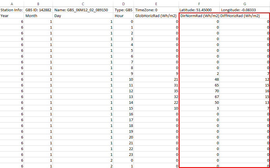
From Legend Values set the units to whatever you are comfortable with:
Select both Automatic and Logarithmic for the Legend
Click Start Rendering
You will submit the same set of 3D views for rendering again using a different legend scale.
Repeat the settings above in i-viii. For the Legend, select 0 – 200 Footcandles, or 0-2000 Lux.
Click Start Rendering
Review Results, you have to click on Render Gallery from the View tab to see your results.
Results
We can take several conclusions from our illuminance renderings:
We have represented the amount of light falling on the surfaces, that’s why in perspective renderings windows interiors have such a low illuminance values.
Light Shelf design option is better to distribute light around our classroom, it brings light further in the classroom.
Skylight option creates uncomfortable spots around the class around the year.
Regarding floor plan renderings most of the rooms receive acceptable levels of daylight.
With this kind of renderings, we can determine if there is enough light to perform required tasks regarding EngineeringToolbox.com classification.
In lighting design as reference we can take recommended indoor light levels from EngineeringToolbox.com. For more precise information we can attend local regulations.
Activity | Illumination (lux, lumen/m2) |
Public areas with dark surroundings | 20 - 50 |
Simple orientation for short visits | 50 - 100 |
Working areas where visual tasks are only occasionally performed | 100 - 150 |
Warehouses, Homes, Theaters, Archives | 150 |
Easy Office Work, Classes | 250 |
Normal Office Work, PC Work, Study Library, Groceries, Show Rooms, Laboratories | 500 |
Supermarkets, Mechanical Workshops, Office Landscapes | 750 |
Normal Drawing Work, Detailed Mechanical Workshops, Operation Theaters | 1,000 |
Detailed Drawing Work, Very Detailed Mechanical Works | 1500 - 2000 |
Performance of visual tasks of low contrast and very small size for prolonged periods of time | 2000 - 5000 |
Performance of very prolonged and exacting visual tasks | 5000 - 10000 |
Performance of very special visual tasks of extremely low contrast and small size | 10000 - 20000 |
Some rules of thumb:
<100lux = insufficient light
100<x<2000 = useful daylight
>2000lux = too much daylight
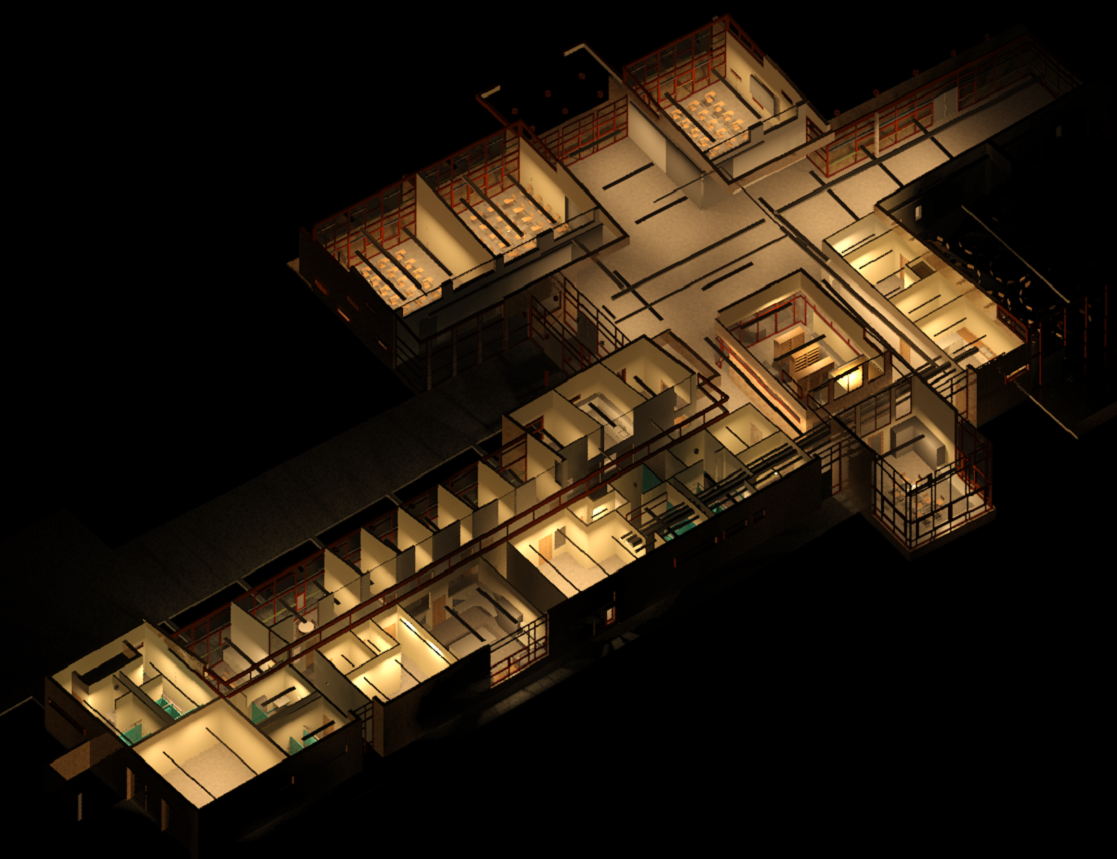
Try to make your own light renders but, be careful with light source configuration! Luminance renderings from artificial lights as image below are easier and faster to create.
LEED Plugin
It’s also possible to do LEED daylighting validation analysis for Revit with a free plugin:
http://www.autodesk.com/products/lighting-analysis-revit/overview
If you are a LEED girl or guy. Give it a try!
Placing Cameras for Illuminance Renderings
Here’s some guidance on how to use and place a 3D camera to approximate a 2D floor plan view for illuminance simulations.
Do NOT do a section cut of the building!
The method using a section cut doesn’t work for daylighting scenes, because it actually removes the top part of the building from the camera view. This would mean your illuminance render assumes there is no roof!
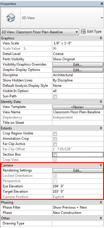
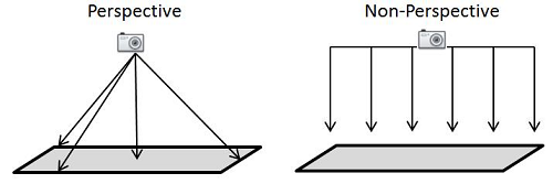
What you need to do to get a good plan view for Revit illuminance simulations is to create a non-perspective 3D camera looking straight down, and located between the ceiling and the floor of the level of interest. Typically you should put the camera at the floor plan cut plane about 1.20 m above the floor.
Select a Floor Plan view of the floor you want to have your illuminance rendering of.
From the View ribbon, select 3D View, then Camera.
Before placing the camera, it is very important you deselect Perspective to create an orthographic 3D view.
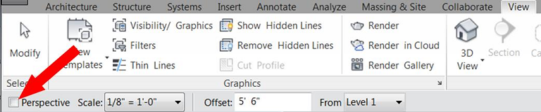
Place the camera anywhere in the view. Don’t worry about placement or where you point it. We will change this setting in following steps.
After placing the camera, the camera view will appear. Use the view cube to rotate the camera to the TOP view.
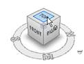
In the camera Properties, change the Eye Elevation so it is below the elevation of the ceiling, but above the elevation of the floor for the level you are interested in.
The Eye Elevation is the height of the camera. Best practice is to place the Eye Elevation about 4 feet above the floor plan elevation you are interested in.
The Target Elevation is how far the camera will be able to “see” into the model. Change the Target Elevation so it is below the elevation of the floor (any value less than the floor plan elevation you are interested in --typically a value of 0, or the ground plane, will be sufficient).
You can use a section/elevation view to help determine what these values should be.
Finally, Crop the view properly

Spaces
Spaces in Revit are like rooms on MEPsteroids. Spaces drop lot of information about systems, also about lighting.
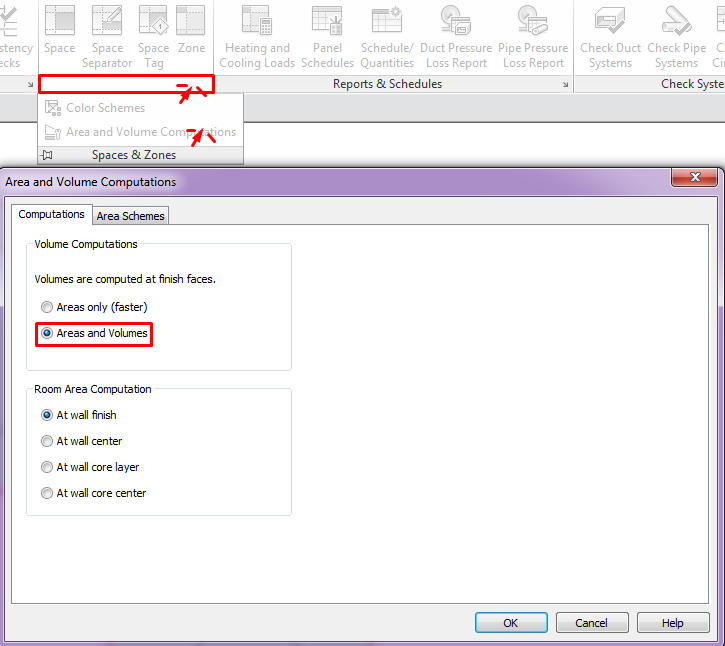
First of all you need to model Spaces, obviously. Second, activate Area and volume computations. Analyze tab > Spaces and zones > Area and volume computations.
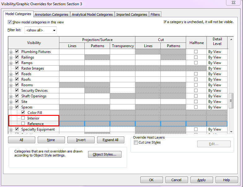
Spaces are always hide by default in all views, you cannot see them in 3D views, so when you want to see your spaces in your floor plan or section, press VV on your keyboard and go directly to Visibility/Graphic Overrides, you have to check the boxes Interior and reference. If you don’t want to make this again and again, go and create a template!
You have to ensure that your spaces are correctly occupying all the volume.
Remember that base of your space mustn't be over level associated (where space was drawn) computation height. Take this into account when start modelling, specially if there are sloped floors.
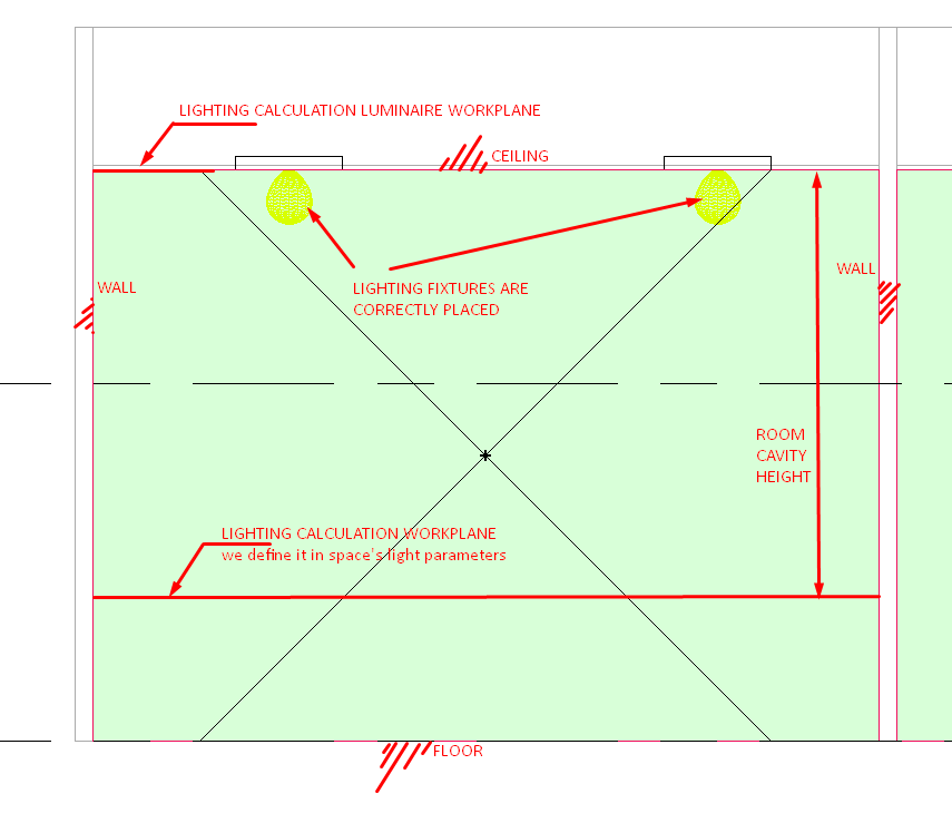
Well, there are some parameters inside spaces which are related to lighting. In fact there is a complete parameter group inside spaces for lighting.
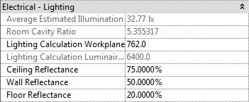
Let’s describe them:
Average Estimated illumination takes the initial intensity lumens from every lighting fixture:
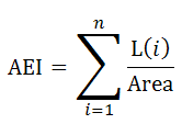
L = Initial intensity * Light Loss Factor * Coefficient Utilization
These come from lighting fixtures’ parameters
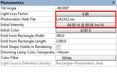
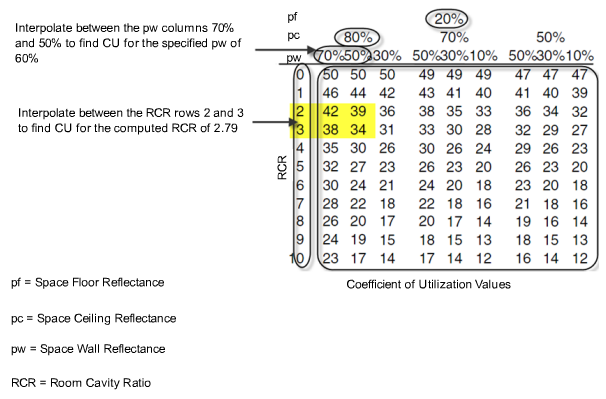
The Coefficient of utilization is computed based on the Space reflectance properties (ceiling, wall, and floor), as well as the space's Room Cavity Ratio.
Room Cavity Ratio = 2.5 * Room Cavity Height * Perimeter / Area
Room Cavity Height = Lighting Calculation Luminaire Plane - Lighting Calculation Workplane Height
Lighting Calculation Luminaire Plane is automatically calculated by our space and Lighting Calculation Workplane Height has to be filled by us.
With .ies file revit automatically calculates the Coefficient of utilization. Image below is a manual approach to Coefficient of utilization from an excel luminaire spreadsheet.
Tips&Tricks
- Material properties: take profit of the options on the Appearance menu of the Material Browser
- Lighting: Set properly the location of the project on Manage > Location, and model the building’s surroundings for exterior renders. Enable the sun path and the shadows (+).
- Lighting fixtures: make sure the settings on your light-bulbs adjust to the project requirements (in terms of shape and photometry).
- Lighting analysis: remember the lighting settings apply only for one view. Take profit of the tool Render in Cloud.
- Cameras: remember that 3D views must be Non-Perspective.
- Spaces: make sure your settings are properly modelled, this is, always upon the floor.
Conclusion
Revit is a powerful tool to perform renders and lighting analysis, but this task requires proper setting of materials, project lighting and light fixtures modeling and configuration. This guide provides expertise on how to take profit of such potential, providing key tips to achieve high quality results.
Associated Files
- Audubon_Classroom_Daylighting_2015
Hi There,
Im a little confused about the Visual Transmittance chart. If a window assembly has a VT value of 90%, why is the value for 28.6mm glass less than 3mm glass. Surely 90% is 90% and they should have the same value.
thanks
A
Hi Alex
This is the way Revit works as per its documentation when you perform Lighting Analysis inside it, it’s not about how TVis physically works. If you have 2 number of glazing panes actually modelled of 3mm the RGB you have to setup in material properties for a 90% TVis is R154, G154, B154. Note that Analytical properties of the pane are not used for Lighting Analysis inside Revit, therefore TVis parameter is useless.
Hope it helps
Regards
Hi, Thank sir, Now I’m leaning Revit by mysefl. Your document is very good. But I can’t download file from your link. Please, fix your link or sent file to my email.Thanks.