
Level Of Development
BIM Concepts
Level Of Development
Objectives
Understand the concept behind LOD and how to work with that when dealing with BIM Models, requirements and documentation.
Description
A BIM model or set of models contains a large amount of elements or objects. Those objects can contain a large amount of information, to represent several aspects of the project or the building.
Usually, in a project there are several parties involved (client, designers, consultants, all kind of intermediaries, building contractors), so it is critical to determine how precisely they are going to define the project, how much information will be included, how reliable that information is going to be and what for, and what can they expect from other models and disciplines.
And that should be defined for each project stage or main milestone, also having in mind specific deliverables needed for specific functions or intended BIM model uses.
For those reasons, a common framework about development and certainty of information in projects is needed. That makes collaboration easier. Every stakeholder will use the same language so that they can understand each other properly.
The framework would describe and establish in advance the depth of information to be included in the elements composing the model and the adequate uses and applications of that information (which sometimes is carried intended in models, but often unintentionally). Thus it will be clear how models can be trusted:
- We specify what information is reliable.
- We specify for which purposes it is reliable.
- We specify the degree of precision to which it is reliable.
That is LOD. It is a language, that serves to know what to expect, and the amount of certainty about the properties, features and specifications of a given element.
With a sample we can understand better this thing about certainty of information:
There can be a Functional Description:
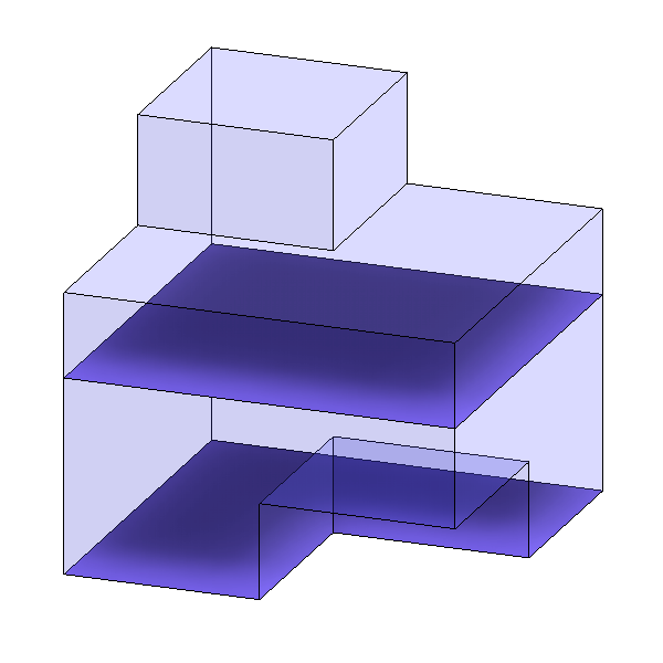
In an early stage of the project we place a HVAC equipment. Its appearance is simple, it is just a box, and the information attached is not much. But somehow we have to make it clear what can we use this model for.
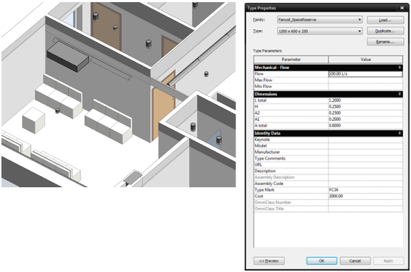
How reliable is that component in this model?
- There is a HVAC equipment, with approximate spatial requirements, in a certain position.
- Rough calculations estimate an approximate Flow need for that equipment.
- We find a proposed cost for the equipment.
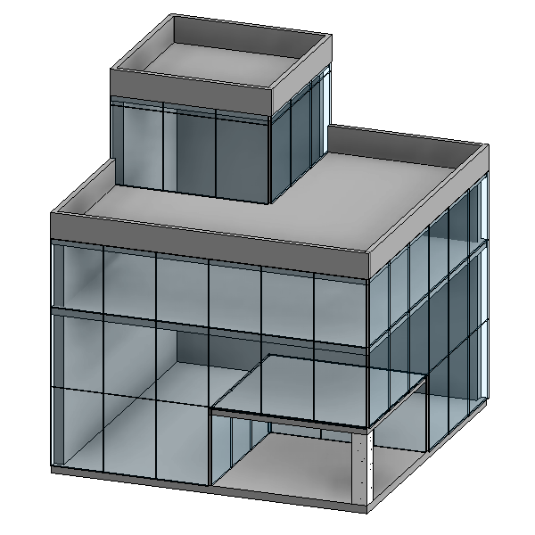
There could be Information for Construction
Later in the project, there is a lot more information about that object. At this point, we have to describe also how far we can trust that information.
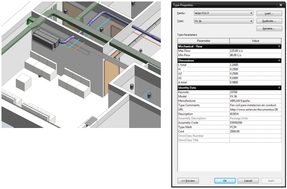
How reliable is that component in this model?
- There is a HVAC equipment, with specific spatial requirements, in a certain position.
- A specific model has been selected. Also we know the manufacturer.
- That component has a concrete flow rate and power consumption.
- We know how much it cost.
The effort to include such information in the model should follow the impact that information can have on the whole project development, and the goals we can achieve in the project. Meaning for example:
- There is no point in modelling and include a lot of information about costs and models in elements if we only intend to perform spatial coordination between disciplines.
- For a detailed cost estimation of a project we will need accurate modelling of elements, and detailed information about them.
It is hard to establish the LOD of a complete model as it will probably contain different elements at different levels.
That is why it is recommended to detail a “Model Production and Delivery Table”, more commonly referred to as a “Responsibility Matrix”, to clarify what information is going to be produced at any stage and by who. And moreover, you assign an LOD code against each building component or system at each progressive stage of the project so the complete team knows what to expect.
LOD Classification Standards
There are several systems to classify LOD in models, different standards to adhere to depending on the geographical location or the reference institution.
There are two main LOD Standards or frameworks that are widely used, since they correspond to the main two blocks of influence: US and UK. We will refer to those in this document.
- In the US we will find the American Institute of Architects (AIA) - BIM Forum LOD Standard
- In the UK we will find the BSI - British Standard Institution Specification (BS EN ISO 19650)
1 (USA) BIM Forum LEVEL OF DEVELOPMENT
(See BIM Forum LOD Specification 2019 document)
Standard commonly used in the USA and areas of influence.
This LOD Framework is proposed by the AIA (American Institute of Architects) and developed by the BIM Forum It provides an industry-developed standard to describe the state of development of various systems, assemblies, and components within a BIM Model. This standard enables consistency in communication and execution by facilitating the detailed definition of BIM milestones and deliverables.
1.1 LOD Acronym
In this context LOD shall be understood as:
- Level
- Of
- Development
Level Of Development | = | Level of Graphical Detail * | + | Level of Information Included |
LOD | = | LOd* | + | LOI |
*Level of Graphical Detail is also known as Level of Detail or again, LOD, that is why there is so much confusion about the terms. So LOD shall be understood differently depending on the context.
1.2 The LOD Standard
The Level of Development (LOD) Specification is a reference that enables practitioners in the AEC Industry to specify and articulate with a high level of clarity the content and reliability of Building Information Models (BIMs) at various stages in the design and construction process.
It defines and illustrates characteristics of model elements of different building systems at different Levels of Development, organized according to CSI Uniformat 2010. The intent of this document is to help explain the LOD Framework and standardize its use so that it becomes more useful as a communication tool.
Remarks:
- The LODs are not defined by design phases. Rather, design phase completion, as well as any other milestone or deliverable, could be defined through the LOD language.
- There is no such thing as a “LOD ### model”. Project models at any stage of delivery will invariably contain elements and assemblies at various levels of development.
- LOD Tables or definitions do not replace BIM Execution Plan documents. They complement them. Project information needs will vary from project to project, and therefore will not be included in the general specifications of the LOD definitions. It will be then addressed in the individual BEPs.
- LOD Specifications are a communication tool.
- The LODs provide five snapshots of the progression of an element from conceptual to specified development, there are many steps in this progression between the defined LODs. LOD definitions, then, should be considered minimum requirements.
- LOD Definitions are Cumulative. For a given element each LOD definition includes the requirements of all previous LODs. Thus for an element to qualify for LOD 300 it must meet all the requirements for 200 and 100 as well as those stated in the LOD 300 definition. This rule has an exception for LOD 500, as it is explained in the next section of this document.
- The LOD Specification facilitates the application of a pull-planning process to the modelling effort, limiting the development of model elements and information to that which the team identifies as useful.
- Much model information is common across several information exchanges. The LOD Specification facilitates the definition of models that will support multiple exchanges for various uses. Intended uses of models should be clearly included in the BEP documents.
1.3 Fundamental LOD Definitions
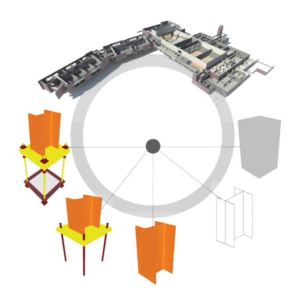
LOD 100
The Model Element may be graphically represented in the Model with a symbol or other generic representation, but does not satisfy the requirements for LOD 200.
LOD 100 elements must be considered approximate.
LOD 200
Elements are a rough representation of the intended object, containing basic functionality and approximated dimensions. Usually the information contained is poor or nonexistent.
LOD 200 often corresponds to the output of schematic design.
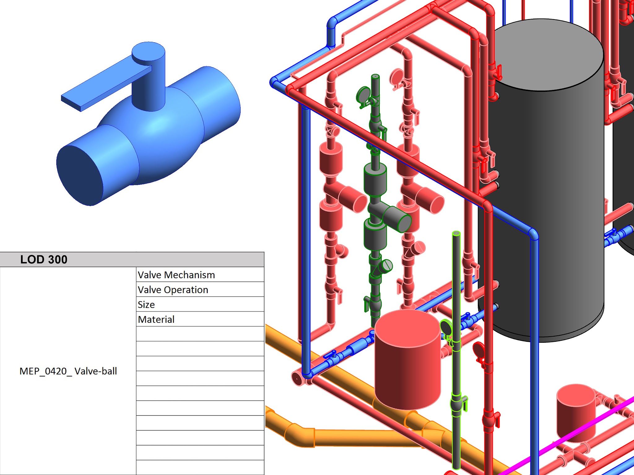
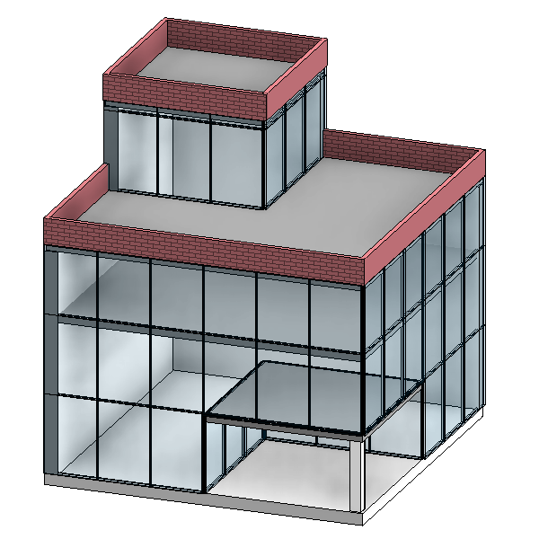
LOD 300
Elements contain a decent representation of their features, both graphical and functional.
This is the minimum LOD an element must be specified in order to define its construction and assembly.
A detail design project often corresponds to LOD 300.
LOD 350
There are intermediate states, like this widely used LOD 350.
It is the result of the need for a LOD that would define model elements sufficiently developed to enable detailed coordination between disciplines – clash detection/avoidance, layout, etc–. Usually the requirements for this use of models are higher than those for 300, but not as high as those for 400, thus it was designated LOD 350.
Parts necessary for coordination of the element with nearby or attached elements are modeled. These parts will include such items as supports and connections.
LOD 350 could correspond to a detail design project + detailed coordination between disciplines.
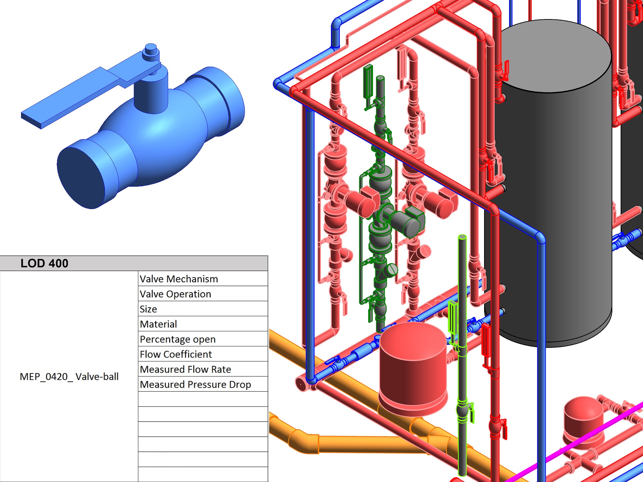
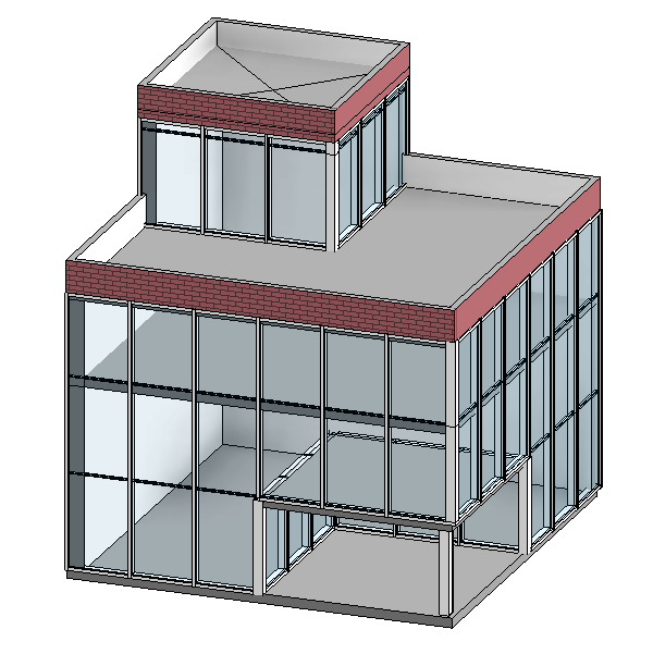
LOD 400
Elements are defined as they will be built, containing all necessary parameters for procurement, assembly and commissioning.
Achieving a LOD 400 is only possible when contractors are involved, as it will be subject to construction final budget and capabilities.
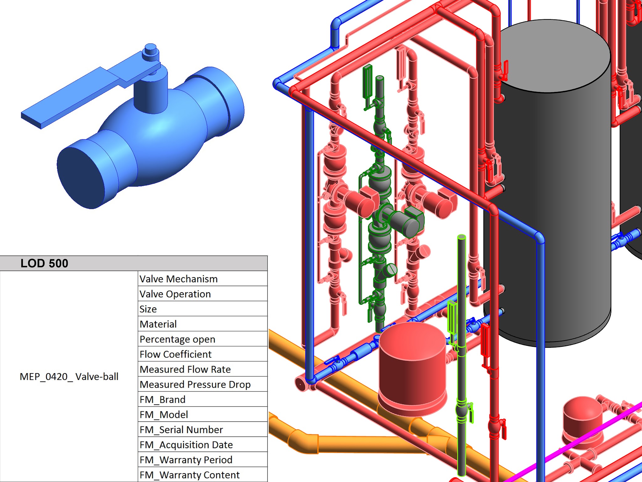
LOD 500
As previously stated, LOD stages are cumulative. But LOD 500 is not a linear evolution of LOD 400, as could be understood for what happens in the previous levels.
It is rather a functional representation of building elements in the operation phase. This means only those objects which are relevant for building maintenance and use are important in this level.
More important than geometrical accuracy is the information attached to objects.
2 (UK) BS EN ISO 19650 LEVEL OF MODEL DEFINITION
(See BS EN ISO 19650 document)
Standard commonly used in the UK and areas of influence.
The BS EN ISO 19650 document provides an industry-developed standard to describe the state of development of various systems, assemblies, and components within a BIM Model. This standard is included in the named framework document: Specification for information management for the capital/delivery phase of construction projects using building information modelling.
2.1 LOD Acronym
In this context LOD shall be understood as:
- Level
- Of
- Model Definition
Level Of Model Definition | = | Level of Graphical Detail * | + | Level of Information |
LOD (LOMD) | = | LOD* | + | LOI |
*Level of Graphical Detail is also known as Level of Detail or again, LOD, that is why there is so much confusion about the terms. So LOD shall be understood differently depending on the context.
2.1 The LOD Standard
It defines and illustrates characteristics of model elements of different building systems at different Levels of model definition, and what the models are reliable on at each stage. In this case elements will conform and relate to Uniclass classification tables.
Contrary to what the BIM Forum standard advocates, the BS EN ISO 19650 document clearly connects the Levels of model definition to the UK project stages.
Remarks:
- The minimum level of detail needed by the team or the employer for each model’s purpose shall be defined.
- It is wasteful for the supply chain to deliver a greater level of detail than is needed which may also overload the IT systems and networks available. Again this warning against over-modelling.
- The level of model definition required in a model at an information exchange shall be defined in the Employer Information Requirements, directly connected with the intended uses of the model.
- The levels of model definition shall be articulated in the BEP and understood by all the stakeholders involved.
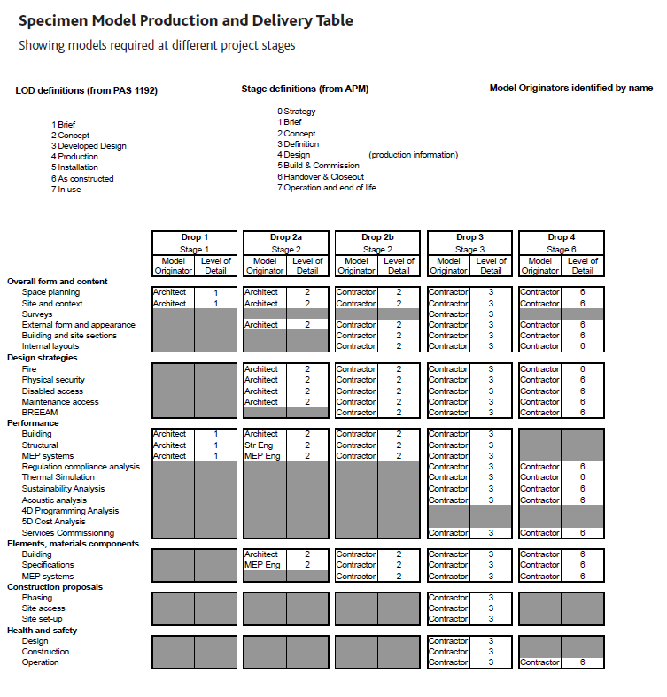
- There should exist a Model Production and Delivery Table that includes the LOD that models need to meet at the project stages or data drops. It is recommended that the table includes not MODELS but ELEMENTS.
In the following table we will find the correspondence between Project Stages (from APM) and LOD Definitions. There is a direct relationship, but not always they should be related in that way. Remember that is advisable to specify element LODs and not Model LODs.
(For further information see BS EN ISO 19650 document):
Project Stage | Level of Model definition | Description | What the model can be relied upon for |
1 Brief | 1 Brief | At briefing stage, the graphical model will either not exist or will inherit information from the AIM (for work on existing buildings and structures). | Model information communicating the brief, performance requirements, performance benchmarks and site constraints. |
2 Concept | 2 Concept | At concept design stage the graphical design may only show a massing diagram or specify a symbol in 2D to represent a generic element. | Models which communicate the initial response to the brief, aesthetic intent and outline performance requirements. The model can be used for early design development, analysis and coordination. The model can be used for basic coordination, sequencing and estimating purposes. |
3 Definition | 3 Developed Design | At design stage the objects shall be represented in 3D with the specification attached. The level of detail should as a minimum represent the space allocation for the product’s access space for maintenance, installation and replacement space in addition to its operational space. Generalised systems with approximate quantities, size, shape, location and orientation. | A dimensionally correct and co-ordinated model which communicates the response to the brief, aesthetic intent and some performance information that can be used for analysis, design development and early contractor engagement. The model can be used for coordination, sequencing and estimating purposes including the agreement of a first stage target price. |
4 Design | 4 Production | At definition stage the object shall be based on a generic representation of the element. The specification properties and attributes from design allow selection of a manufacturer’s product, unless the product is nominated, free issue or already selected. It is a “design intent model representing the end of the design stages. | A dimensionally correct and coordinated model that can be used to verify compliance with regulatory requirements. The model can be used as the start point for the incorporation of specialist contractor design models and can include Information that can be used for fabrication, co-ordination, Sequencing and estimating Purposes. |
5 Build & Commision | 5 Installation | At build and commission stage any generic object shall be replaced with the object procured from the manufacturer. Any essential information to be retained shall be reattached or relinked to the replacement object. | An accurate model of the asset before and during construction Incorporating co-ordinated specialist subcontract design models and associated model attributes. The model can be used for sequencing of installation and capture of as-installed information. |
6 Handover & Closeout | 6 As Built | At the handover and close-out stage all necessary information about the product shall be included in the handover document and attached to the commissioning and handover documentation. The as-constructed model shall represent the as-constructed project in content and dimensional accuracy. | An accurate record of the asset as a constructed at handover, including all information required for operation and maintenance. |
7 Operation | 7 In use | At the in-use stage, the object’s information shall be updated with any supplementary information such as maintenance records or replacement dates, and objects that have been changed or replaced with different equipment shall be updated accordingly. | An updated record of the asset at a fixed point in time incorporating any major changes made since handover, including performance and condition data and all information required for operation and maintenance. |
Following table is a sample of a Model Production and Delivery Table, as included in the CIC BIM Protocol (See CIC BIM Protocol document):
3 BIM Forum LOD vs BS EN ISO 19650 LOD
Comparison table. There is not a direct and perfect match between both standards, but the following relationship is the informal relationship that Modelical proposes:
LOD | Level of Definition (BS EN ISO 19650) | LOD | Level of Development (BIM FORUM 2019) |
1 Brief
| Model information communicating the brief, performance requirements, performance benchmarks and site constraints. At briefing stage, the graphical model will either not exist or will inherit information from the AIM (for work on existing buildings and structures).
| 100
| The Model Element may be Graphically represented in the model with a symbol or other generic representation, but does not satisfy the requirements for LOD 200. Information related to the Model Element (i.e. cost per square foot, tonnage of HVAC, etc.) can be derived from other Model Elements. |
2 Concept
| Models which communicate the initial response to the brief, aesthetic intent and outline performance requirements. The model can be used for early design development, analysis and coordination. Model content is not fixed and may be subject to further design development.
| 200 | The Model Element is graphically represented within the Model as a generic system, object, or assembly with approximate quantities, size, shape, location, and orientation. Non‐graphic information may also be attached to the Model Element.. |
3 Developed Design | A dimensionally correct and co-ordinated model which communicates the response to the brief, aesthetic intent and some performance information that can be used for analysis, design development and early contractor engagement. The model can be used for coordination, sequencing and estimating purposes including the agreement of a first stage target price. | 300
| The Model Element is graphically represented within the Model as a specific system, object or assembly in terms of quantity, size, shape, location, and orientation. Non‐graphic information may also be attached to the Model Element. |
4 Production | A dimensionally correct and coordinated model that can be used to verify compliance with regulatory requirements. The model can be used as the start point for the incorporation of specialist contractor design models and can include information that can be used for fabrication, co-ordination, sequencing and estimating Purposes. | 350 | The Model Element is graphically represented within the Model as a specific system, object, or assembly in terms of quantity, size, shape, location, orientation, and interfaces with other building systems. Non‐graphic information may also be attached to the Model Element.
|
5 Installation | An accurate model of the asset before and during construction incorporating co-ordinated specialist subcontract design models and associated model attributes. The model can be used for sequencing of installation and capture of as installed information. | 400 | The Model Element is graphically represented within the Model as a specific system, object or assembly in terms of size, shape, location, quantity, and orientation with detailing, fabrication, assembly, and installation information. Non‐graphic information may also be attached to the Model Element. |
6 As Constructed | An accurate record of the asset as a constructed at handover, including all information required for operation and maintenance | 500 | The Model Element is a field verified representation in terms of size, shape, location, quantity, and orientation. Non‐graphic information may also be attached to the Model Elements.
|
7 In use | An updated record of the asset at a fixed point in time incorporating any major changes made since handover, including performance and condition data and all information required for operation and maintenance.
| 500 | Updated model.
|
4 LOD and BIM Model Uses
A BIM use is a concrete action developed within the BIM Model.
A model should be developed at each stage to the point that it includes the information that is useful for the intended use and the project status. Again the modelling effort should be limited to what is useful at each project milestone.
Intended uses of models should be clearly included in the BEP documents.
This is a small table defining the adequate model LOD for a specific scope:
Model Use | LOD 200 | LOD 300 | LOD 400 | LOD 500 |
Coordination review and clash detection | Adequate | Optimal if also done LOD 200 | Adequate if also done in LOD 300 | Unnecessary |
4D Sequence | Adequate | Adequate if also done in LOD 200 | Adequate but intensive labour | Unnecessary |
Quantity take-off and review | Not adequate | Adequate | Optimal | Adequate |
Site planning | Adequate | Unnecessary | Highly unnecessary | Unnecessary |
5 LOD and BIM Model Content per discipline
Brief sample:
Model Use | LOD 300 Content to be included | ||
Architecture | Structure | MEP | |
Coordination review and clash detection | •Interior partitions. •Openings, windows and doors •Staircases and ramps. Elevators | •Walls, columns and retaining walls •Slabs and mat slabs •Framing, beams, openings | •Ducts and mechanical equipment •Sanitary downpipes and branches •Water supply system •Fire fighting system •Shafts and shunts •Lighting fixtures and panels |
4D Sequences | •Construction joints •Concrete pouring joints •Facade assemblies | •Earthworks •Structure assemblies •Formwork •Cranes and machinery | •Only major elements |
Quantity take-off and review | •Partitions and facade elements with specifications •Windows and openings •Staircases and ramps. Elevators •Finishes •Furniture | •Walls, columns and retaining walls •Slabs and mat slabs •Framing, beams, openings •Foundations •Materials and coding •Reinforcement general quantities | •Ducts and mechanical equipment •Sanitary downpipes and branches •Water supply system •Fire fighting system •Shafts and shunts •Valves and pumps •Lighting fixtures and panels • |
Site planning | •Site facilities. Fencing •Cranes and machinery •Formwork and centering | ||
Bottom-line
- Model sparingly to meet the needed model development so it can serve the intended uses of the model.
- Intended uses of the model should be clear in advance, so that the project and model development can be programmed accordingly.
- There is no point in defining whole models LODs. It is better to focus on element LODs.
Associated Files
- BIM FORUM LOD Specification 2019
- BS EN ISO 19650
- CIC_the-bim-protocol
The Blog is very deeply Explain about each and every point of Level Of development. I also like your blog content also. So thank for sharing with us also.
Thank you for your kind comment.