
Revit Structure
Best Practices
Revit Structure - Best practices
Objectives
- To understand the best techniques to model Structures in Revit.
Prerequisites
- The user is able to use Revit files.
- The user has basic skills in BIM modelling with Revit Structure, and understands the terminology.
Description
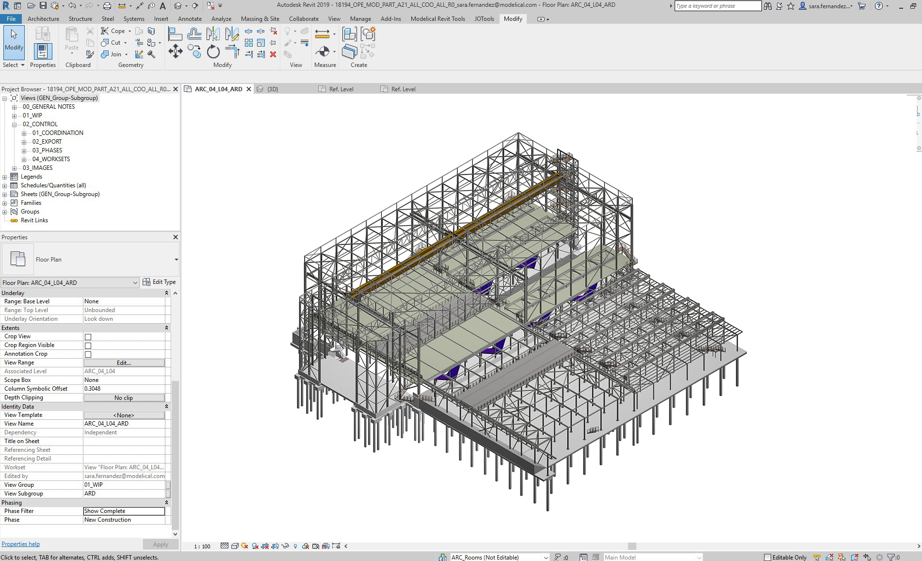
Structural modelling in Revit can be very useful, but it’s key to manage our model properly, in order to keep it clean and organized, and the file fluent and weight optimized. This document explains key tips to achieve so.
Procedure
Project configuration
Analytical model generic settings
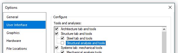
Disable the automatic Analytical Support Check feature if you are not going to use it, it may significantly decrease the performance of the model. To disable this feature, go to File→ Options→ User Interface, and uncheck “Structural analysis and tools”. Please make sure to modify the User Interface setting in ALL user local computers who are working on this project:
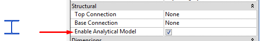
Check out the “Enable analytical model” for structural elements if you are not going to use it. It will greatly improve the performance of the model:
Level of Development
Do not overmodel. That means that it should be clear which level of development (LOD) the elements in a model should reach.
LOD requirements will be specified prior to start modelling, and should be in accordance to the intended uses and project phase.
LOD | CONCEPT PHASE | STANDARD PHASE | EXAMPLE |
100 | Conceptualization | Schematic Design | Little model content with some massing, 2d lines and a structural narrative. |
200 | Criteria design | Design Development | General structural objects are modeled to reserve space. |
300 | Detailed Design | Construction Documentation | Create 2D construction documents, general estimating and 3D spatial validation |
350 | Beyond Detail Design | Pre-Con | Detailed estimating, and 3D Spatial Validation |
400 | Fabrication Detail | Construction Administration | Shop Drawings |
500 | Facility Management | Hand Over | Maintenance & Renovation |
Modelling in Structure Projects
Modelling hierarchy
The information that is available in order to model a building, particularly the structure, very often contains errors and lack of precision due to an inconsistent AutoCAD or similar work. This information should therefore be adequately reinterpreted and filtered so as to avoid any source of further irreversible inaccuracies when developing a BIM model.
- The modeling process should begin with the study of the symmetries and general geometrical relationships among the different parts of the building.
- The main arrangement of the structure and facade should then be established, taking into consideration first the symmetries and then those annotations that are clearly expressed.
- The next step consists of the placement of columns aligned with the structural axis’ intersections; in case of eccentricity columns should be respectively related to axes through appropriate dimensions.
- Subsequently, beams, structural walls and floor openings should be placed in relation to columns (aligned to face, to axis, with a particular offset…) of the corresponding level, respecting the load paths.
- The logic connection among elements of different levels is to be respected, provided that the relation keeps some common sense.
- Afterwards, the floor boundaries should be delimited taking as a reference the elements mentioned in the previous points, as long as there are no explicit references with properly defined dimensions/offsets.
- Only if there is no clear reference or dimension with respect to an element, this should be located considering the direct measuring from a CAD file or selecting elements from imported files.
Use pick line tool is dangerous in any case at this step, as CAD lines can lead us to eccentric elements, or elements of a geometry more complex than intended.
Modelling Concrete
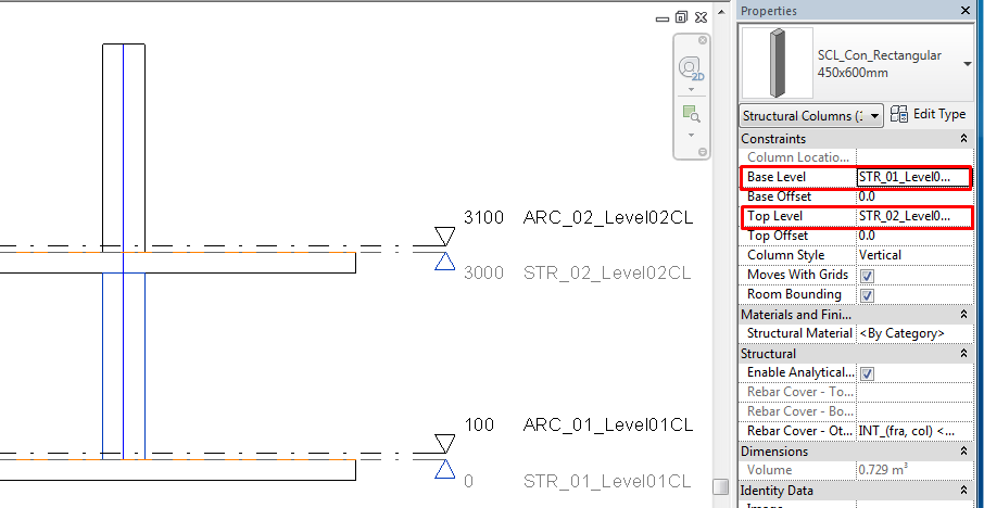
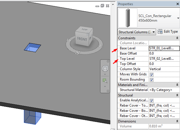
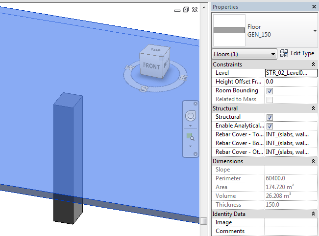
Concrete columns should be modeled floor (bottom face) to floor (top face), enabling them to be scheduled individually according to the construction logic and for quantification purposes. Also to place rebar systems individually on each.
For early scheme designs, walls can be modeled full height then split at a later moment, although this is not recommended as you will lose associated filters.
You cannot tag slab edges (neither they have analytical properties) therefore it's best to use a beam for slab edge thickenings that need to be scheduled.
When modifying a floor you will often get the message - "Would you like walls that go up to this floor's level to attach to its bottom?" - Say No as you are the one who should be in control of which walls are attached to the floor, not the computer.
Openings through Walls should be modeled using structural doors and window families, as this workflow allows quicker placement, editing opening sizes through duplication of families and all information can be viewed in schedules which can also be used to quickly edit.
Beams should be modeled column to column. This means from axis to axis, not from face to face.
It is important to model the way that is going to be built. It will generate the proper Analytical model and using the cut/join tools we can get the correct representation and volume quantities.
Use reference planes to place structural members like beams in sloped workplanes. Name allways the reference planes that are important references in the model.
Be aware that reference planes could have to be included in groups when structural members are hosted on them.
Modelling Steel
If possible, avoid excessive modeling of the 3D connections, such as connection plates and bolts, in Revit Structure. When doing typical detail, create or use 2D detail component connections instead.
All steelwork views to be set to Detail Level: Medium/Fine. Otherwise we will be seeing schematic axis lines for steel members. That is the default behaviour of steel families in coarse level of detail although it could be modified.
Make sure you select the appropriate structural usage from the element properties.This will affect visibility of objects.
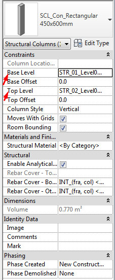
Steel columns should be modeled floor (top face) to floor (top face), enabling them to be scheduled individually according to the construction logic and for quantification purposes.
Beams should be modeled column to column. This means from axis to axis, not from face to face.
It is important to model the way that is going to be built. It will generate the proper Analytical model and using the cut/join tools we can get the correct representation and volume quantities.
Every steel member should be modelled considering the axis line and its insertion in relation to other steel member axis lines. Actual geometry will be cut accordingly.
Use reference planes to place structural members like beams in sloped workplanes. Name allways the reference planes that are important references in the model.
Be aware that reference planes could have to be included in groups when structural members are hosted on them.
Remember that structural truss families are the layout of the truss (rules of creation), but the individual members will act as what they are, this is, instances of beam families (structural framing category).
Cutting elements
Cutting structural elements does not respond always to the same logic as cutting generic elements. There are several options for cutting structural members:
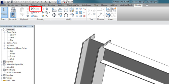
Cope
Maybe you tried “Cope” (Modify tab > Geometry Panel > Cope). But it only works for structural families with the Material for Model Behavior set to “Steel”. And you will need two structural intersecting elements to use it.
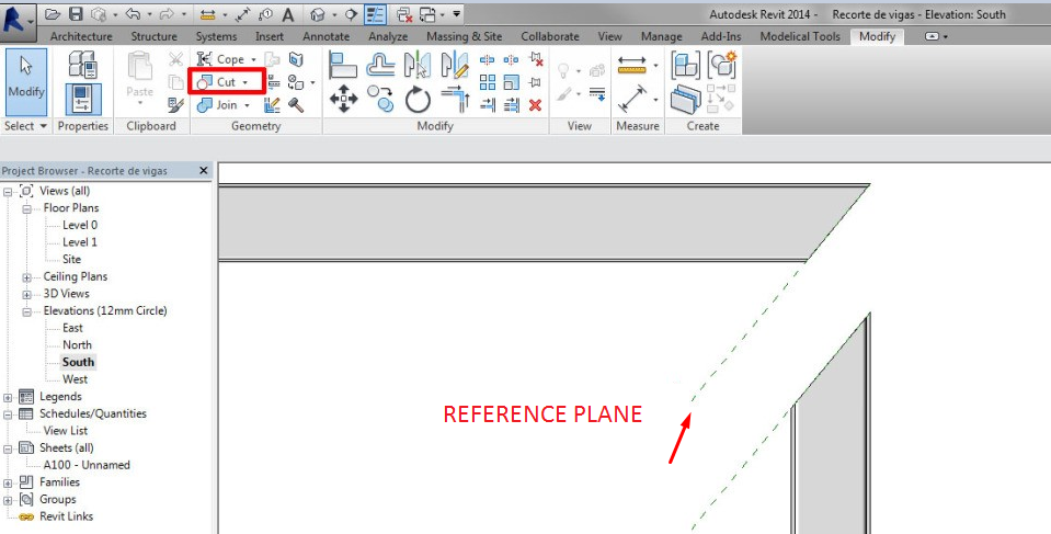
Reference Planes and Cut
Beams and columns ends can be cut at a certain angle using Reference Planes and Cut Tool (Modify tab > Geometry Panel > Cut). That is very useful, and will work for every beam and column except for those with Concrete Material Behavior (Family Parameter).
You can even attach Structural Columns to a Reference Plane, just as you would attach them to a floor or a roof.
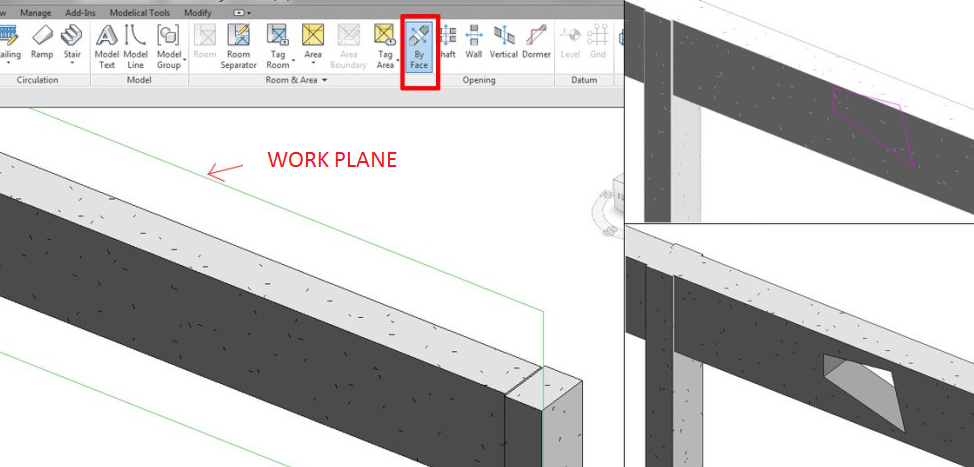
Opening by Face
Other standard tools: Opening by Face (Architecture/Structure tab > Opening Panel > By face).
With this tool you can customize the openings on your structural elements (beams and columns) but with some restrictions: it will always be a through hole, and in one of the perpendicular directions of the beam/column cross section.
Generic Model Families
An In-Place Void Component will not do it, but we can use a void in a Generic Model family. In this case, remember to activate for the Structural Framing and Columns Families the Family Parameter “Cut with voids when loaded”.
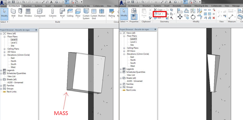
Masses
We can use “in place masses” as well. Not void masses but solid masses, and cut the beam or column with that element.
Masses can be used as auxiliary elements, better than in-place components, because normally they are already a hidden category, non visible in views. Additionally, they won't appear as in-place components in category schedules (in-place components would), because they have their own category.
The only downside is that they do not cut steel elements.
Structural elements information
When we load a structural element like columns or framing elements, the default families do not contain the structural material, which is very important for schedules (in order to get the linear weight of steel elements). Weight (W) and area (A) are set by default, and do not rely on the structural material or shape.
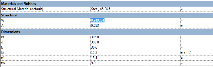
Therefore it is a good practice to add to these families the real area coming from the shape and a linear weight parameter, which depends on the material density and can be customized if necessary:
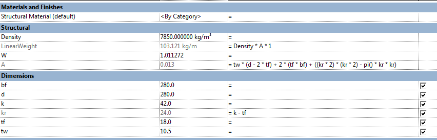
Use shared parameters to create the properties in structural families which are necessary to schedule or tag. Otherwise the information will remain in the family and it will not have any impact on the global model information. Default families do not use shared parameters for dimensional information, which is specially relevant in concrete structural elements.
Rebars
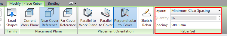
Utilize rebar sets instead of individual rebar elements where possible:
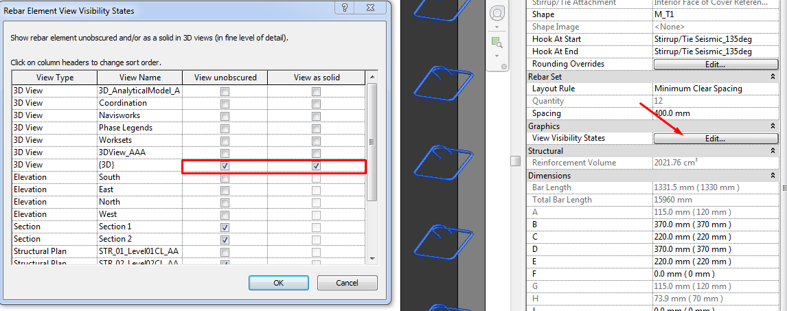
You must take into account that bars have a special visibility, which can be accessed by selecting the own bar and settings in the Properties window, Graphics. In that window you choose for each view 2 possibilities:
- View unobscured. To see the bars through the element that contains them.
- View as solid. To see not as lines but as solid bars.
As this parameter can not be controlled by the Template (as they apply to each bar) a possible solution for them is to modify the transparency of columns/beams, thus bars are equally visible if the option selected is "unobscured" or not.
The rebar cover is controlled by parameters of instance, containing all the elements that can contain them by default. Those categories of elements that can be structural or not, e.g. the Walls or Floors, will show only these parameters if you have selected the option "Structural", but a Structural Foundation will always have enabled those parameters.
Model rebar only when strictly necessary. Use detail elements instead unless a rebar digital model is needed for some purpose. Rebar elements overload models.
2D Details
Standard details will be drafting views. If they are stored in a file apart this file can act as a repository, and then import the details to other project files.
Drafting views should be sorted by the type of detail, and there should be a view naming system.
To insert any drafting view from another document which contains a detail, go to Insert>Insert from file.
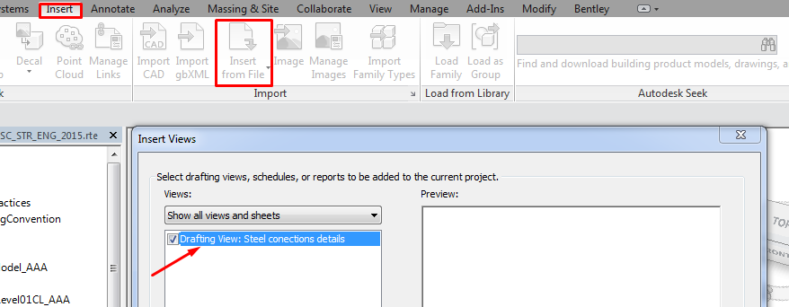
Notice that the only views that can be transferred from file to file are:
- Schedules
- Drafting views
- Sheets with only 2D elements. If they have already model viewports they cannot be transferred.
Use parametric detail elements components to describe concrete elements rebar. In modern versions of Revit they can be scheduled and are very useful for rebar quantifying.
Visibility
Work as much as possible with "Coarse" Level of Detail, it considerably improves the handling of the file. Previous statement does not apply when working with steel elements, which are displayed usually as lines.
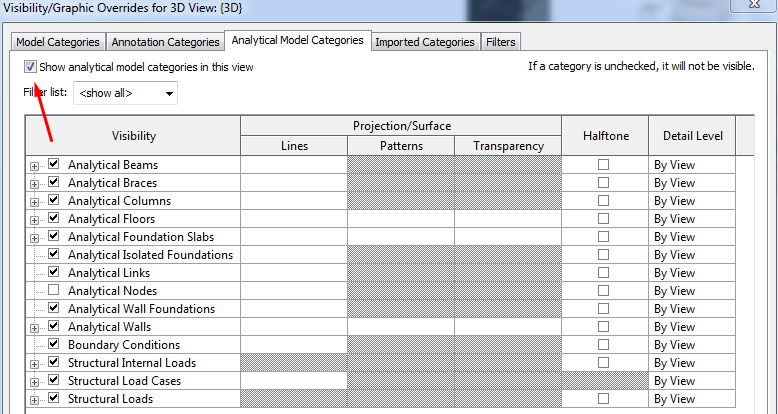
The analytical model can be displayed in all views. In the normal views it tends to be disabled by default. Special views should be created only for the analytical model. It can be useful to have a view to see the analytical model with the physical model with transparency.
The visibility of analytical elements works the same as the visibility of any element of the physical model: first is controlled in general with Object Styles, and in particular for each view with "VV" (Visibility/Graphics Overrides).
If we apply a concrete surface shading, we should make sure to print our drawings using raster processing, as all annotation elements and transparent fill boundaries appear above the surface shade.
Use filters in your views for the above shading of elements, rather than the overall concrete surface shade, which won't shade the ends of slabs, concrete stairs, and tops and sides of walls. Applying surface shading with filters overcomes this problem.
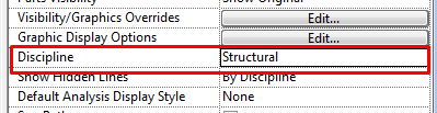
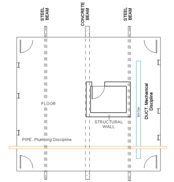
View visibility settings by structural discipline
Non structural Walls and Floors will be hidden. But not the elements (like windows or doors) hosted in them.
Those structural elements (beams, columns, walls) beneath or behind other elements (such as floors or walls), will appear according to the Hidden Line sub-category in the corresponding Model Category (Object Styles or Visibility/Graphics Overrides).
Show hidden lines option can be overriden in any discipline from version 2015 and subsequents.
Other elements will be shown according to Object Styles, Visibility/Graphics Overrides and View Range settings.
Analytical Model
Analytical model will be created simultaneously with the physical model without a conscious effort. Therefore, it’s encouraged to model the physical elements with the needed accuracy so that the analytical model is adequate for calculating.
By default, for the structural members the attached analytical element will be located at:
- Longitudinal axis of columns
- Longitudinal axis of beams
- Top face of floors
- Central line/plane of walls
It may happen that the configuration of the physical model doesn’t fit exactly the analytical model, which is required for the integration with calculation software. Therefore some touch-ups should be done before exporting, especially in connection brackets with beams and slabs, as well as the walls and the slabs of support.
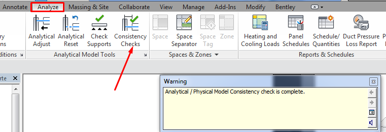
In order to do so, we should click on the Analyze tab, Analytical Model Tools panel, Analytical Adjust to manually adjust the analytical model. From here you can also delete openings that should not be viewed in the analysis. This does not change the physical model.
To "reset" the modifications made: Click Analyze tab, Analytical Model Tools panel, Analytical Reset. The element will return to their form or original scenario according to the physical model.
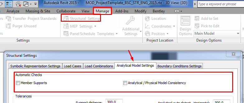
Before exporting the model you should check it: Click Analyze tab, Analytical Model Tools panel, Consistency Checks. A series of warnings indicating possible errors or inconsistencies in the model will appear.
The checks can be activated manually or by default: Structural Settings, Analytical Model Settings, Automatic Checks. Better enable them by default when the model is practically finished.
Analytical lines need to be reset to floor level if they are attached to floors.
For sloped floors the analytical slab will only be sloped as well if the slope was set using a slope arrow. Floors with modified sub-elements will have an horizontal attached analytical slab.
Export
CSiXRevit is a link that enables the exchange of data between ETABS® and Revit (for SAP versions from V15.1.0/1 and ETABS 2013, for earlier versions you can use the IFC format). CSiXRevit supports the following Exchange workflows:
- export from Revit to ETABS/SAP2000
- export from Revit to update an existing in ETABS model
- import from ETABS/SAP2000 to create a Revit model
- import from ETABS to update a Revit model
The Structural Analysis Toolkit for Autodesk® Revit® software is a suite of tools that supports the Building Information Modeling (BIM) process, and allows structural engineers to analyze structures from within the Revit environment.
The toolkit contains the following items:
- Structural Analysis for Revit
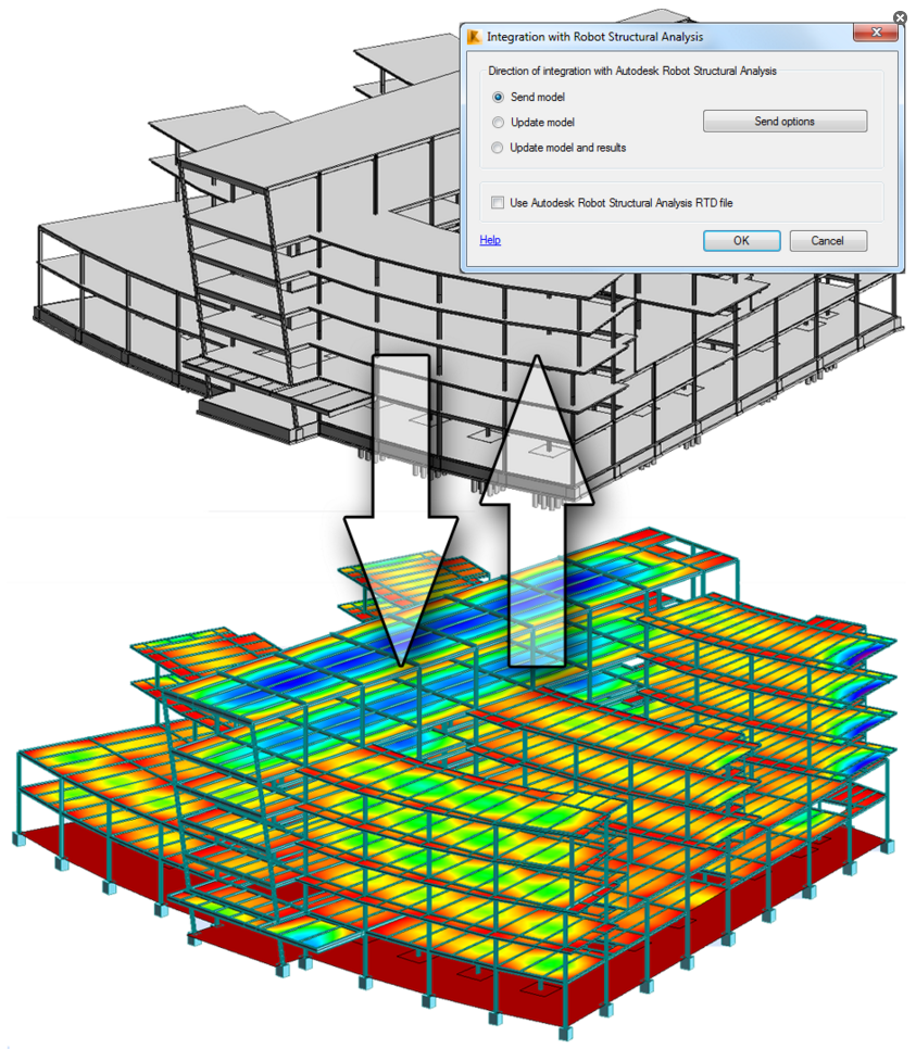
- The link with Autodesk® Robot™ Structural Analysis Professional 2016
- Structural Results Storage & Exploration tools
Using this toolkit, structural designers and engineers can optimize their workflows in the cloud and on the desktop, by using the analytical model built in Revit to conduct cloud-based structural analysis. Accessing the Autodesk 360 services, and by extending the Revit model to Autodesk Robot Structural Analysis Professional software, or supported third party analysis solutions. Once complete, analysis results can be easily stored and explored in the Revit environment.
Tips&Tricks
- Disable the automatic Analytical Support Check unless is extremely necessary, this will increase the performance of the model.
- Modelling hierarchy: follow the recommended modelling hierarchy in order to establish the adequate relations between elements.
- Adjust the structural elements information, as the data provided by default does not reflect the actual properties of the elements in terms of weight and area.
- Model the rebars only if necessary, and in such case, use rebar sets instead of individual rebars.
- Work at Coarse detail level unless you are working with metallic structures.
- Make sure the analytical model is properly connected. Remember that you can delete analytical voids without affecting the physical model.
- Use the Structural Analysis Toolkit to analyze structure inside Revit.
Conclusion
Modelling structures with Revit offers interesting functionalities when it comes to representing, computing, quantifying and planning them, but a good management of the modelling technique is key to keep our model consistent. This document explains several aspects that help the modeller achieve such good management.
i had some problems with beams z offset, they don’t affect the analytical model, i must change the z offset in the start and the end of the beam to adjust right.
This seems like the right behaviour, physical and analytical models go separate ways to give you flexibility.
That’s true, don’t use z offset, use end and start instead, i don’t know why z offset exist, but i don’t think it’s a good modelling practice and especially when analytical model is needed.