
Stairs, Ramps, and Railings
Operation in Revit
Stairs, Ramps, and Railings
Objectives
Be able to create stairs in Revit and understand their properties. Be able to create ramps. Be able to create railings. Railings are very complex elements formed by nested subelements.
Prerequisites
- User has basic skills in BIM modelling with Revit Software, and understands the language used.
- User fully understands data structure in models (category > family > type > instance).
Description
This guideline explains the features of Revit Stairs, Ramps and Railings, it explains the types that we can find, and the process to configure and model them. Stairs are complex elements which can be parameterized accordingly to their constructive nature and accessibility requirements, as well as ramps and railings. This document explains how to set properly their configuration, to achieve elements of high geometrical complexity, properly characterized and controlled.
Procedure
Stairs
Stairs is a model element category whose families are system families.
Prior to stairs modeling datums must already be created (Grids, Levels and/or Reference Planes), and it’s desirable to have placed structural elements that will act as a reference for stairs, such as floors and shafts and beams.
There are two different ways of modeling stairs, by sketch and by component.
In both ways there’s fundamental data to set the calculation rules:
- Maximum riser height
- Minimum tread width
- Base level for the stair to begin
- Top level to reach
Stair by component
When using this tool to model stairs, what you have to set up are the components forming part thereof, namely: runs and landings, which can be combined to give rise to different kinds of stairs configurations.
The stair will have type and instance parameters.
Each part (runs and landings) will have specific type and instance parameters.
When you create a stair, you select a stair type from three predefined system families:
- Cast-In-Place Stair. They resemble the concrete cast-in-place stairs.
- Precast Stair. They resemble concrete precast stairs
- Assembled Stair. They resemble metal assembled stairs, with metal stringers and non monolithic threads.
There are only three system families, but there could be created as many types from each as needed in the project. Types will be different specially when calculation rules have to be different.
Every component you draw will be appearing physically in the model instantaneously.
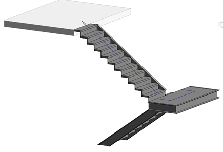
Cast-in-place stairs
As said, it is important to set first the assembly parameters of the stairs:
- Maximum riser height
- Minimum tread width
- Base level for the stair to begin
- Top level to reach
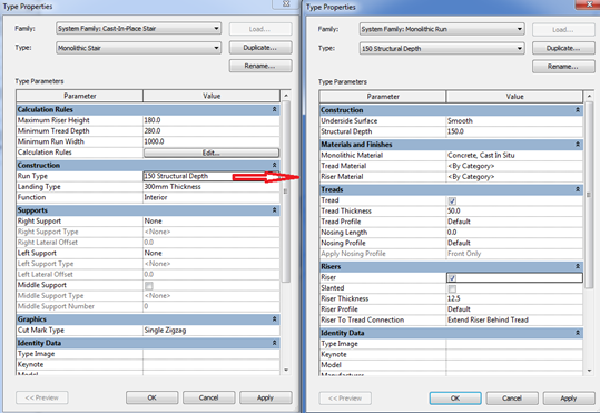
Afterwards the main type parameters of each component of the stair have to be set up:
Run type:
- Run structural depth
- If the underside Surface is smooth (flat) or stepped
- If there is a specific thickness for the tread or the riser in the step.
- Nosing profiles
- Riser to tread connection
Landing type:
- Monolithic (landing) thickness
- If the treads settings are the same as in the run or vary.
Supports: they are not common in this kind of stairs, because they have a monolithic run.
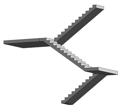
Assembled stairs
Treads and risers remain without a slab for supporting them. In this type of stair, side and/or central supports are commonly used.
As in every stair in Revit it is important to set first the assembly parameters of the stairs:
- Maximum riser height
- Minimum tread width
- Base level for the stair to begin
- Top level to reach
Afterwards the main parameters of each component of the stair have to be set up:
Run type:
- Tread thickness.
- Riser thickness
- Riser to tread connection
- (There is no monolithic run)
Landing type: If the treads settings are the same as in the run or vary.
Supports:
- Right/left support configuration as stringer, and the profile family that is used to model them. Notice that the profile is a stand-alone loadable family that has to be loaded in advance.
- Right/left support configuration as carriage and its depth and width.
- Middle support configuration as carriage and its depth and width.
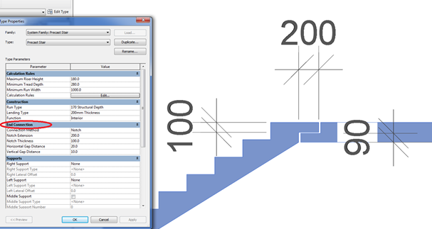
Pre-cast stairs
In this type of stairs you can configure the connection method between the run and the landing to be a notch, assuming that both components are sort of pre-cast parts that rest on other elements.
Again it is important to set first the assembly parameters of the stairs:
- Maximum riser height
- Minimum tread width
- Base level for the stair to begin
- Top level to reach
Then the main parameters of each component of the stair have to be set up:
Run type:
- Run structural depth.
- If the underside Surface is smooth (flat) or stepped.
- If there is a specific thickness for the tread or the riser in the step.
- Nosing profiles
- Riser to tread connection.
Landing type: If the treads settings are the same as in the run or vary.
Landing type:
- Monolithic (landing) thickness
- If the treads settings are the same as in the run or vary.
Supports: they are not common in this kind of stairs, because they have a monolithic run.
Notch dimensions.
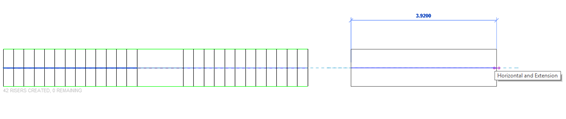
Stair by sketch
In this way of modelling stairs, what is done is to draw a sketch of the staircase to be constructed. The three-dimensional object does not appear until you finished the sketch of the stair.
There is only one family of stairs by sketch, although there can be as many types as needed in the model.
These stairs allow a bit more flexibility in the form of the stair than the stair by components, even though, you can convert the components of a stair by component into components by sketch.
On the stairs by sketch it comes to drawing the stair plan in 2D, specifying the lines that compose it:
- Boundary lines
- Riser lines.
- Runs (a set of boundary and riser lines conforming a run).
The rest of the stair parameters match those that are configured for stairs by component, but in these stairs, all of them are type parameters of the stair itself, and not from the components that form it.
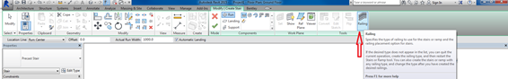
Ramps
Although the ramps can be created through a sloped floor, there is a specific tool for ramps. They work in a similar way as stairs, but they are less complex.
Remember that ramps are architectural elements that barely interact with other model elements, but they are host elements for railings.
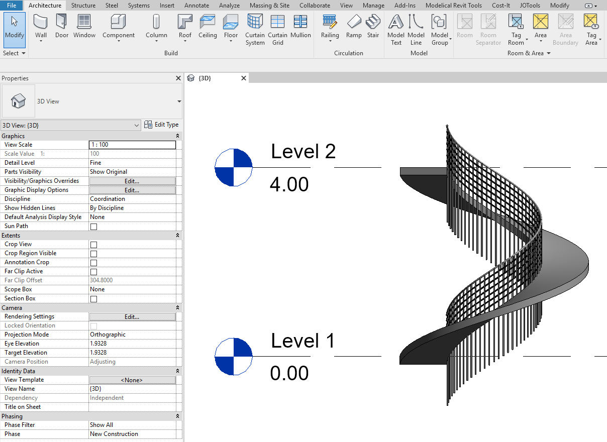
You can create ramps in a plan view or a 3D view.
You use the same tools and procedures for sketching ramps that you use to sketch stairs. Just like stairs, you can define straight runs, L-shaped runs, U-shaped ramps, and spiral ramps.
You can also modify the outside boundary of the ramp by modifying the sketch.
The easiest way to add a ramp is to sketch a run. However, the Run tool limits the design of your ramp to straight runs, straight runs with landings, and spiral ramps. For more control when designing ramps, sketch the run of the ramp using the Boundary and Riser tools.
Most important property of ramps is the slope. To give the slope to a ramp, you have to specify the X value in this relation:
Max Slope = 1/X
Ramps can have the thickness of a floor: Shape>Thick:
Or have an increasing thickness: Shape>Soli:d
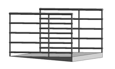
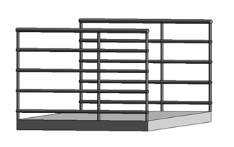
Railings
Railings are system elements in models that are formed by other sub-elements. Some of the sub-elements are system elements as well, other are loadable custom families.
Railings are complex system families.
Is good to know that somehow they are difficult to handle elements and quite restricted in its design for specific details, but at the same time they are flexible elements that allow crazy compositions.
At the time of creating a stair or ramp you can choose whether or not we want the railing. If it is decided not to include the rail at that moment, it can be added later.
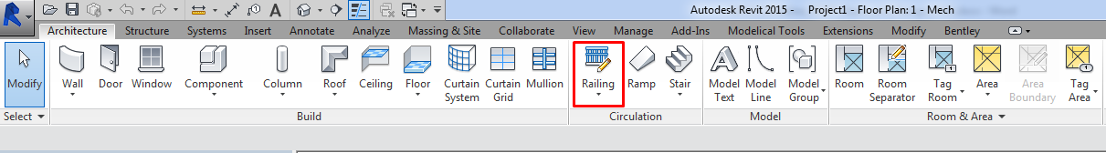
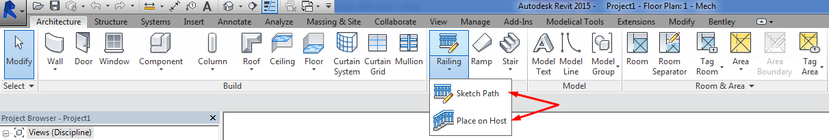
They can be also created independently, Architecture tab > Circulation panel > Railing:
Properties and configuration
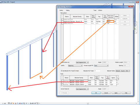
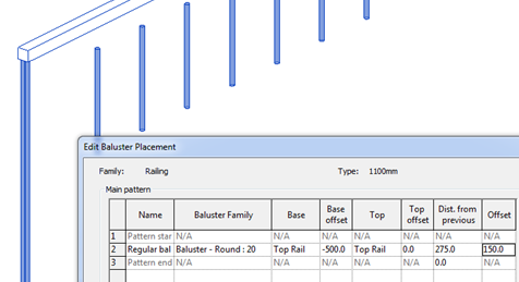
Balusters
They are the vertical elements.
They are loadable custom families that are nested in the railing system family. They have to be loaded into the project in advance.
You can create a new one using the Metric Baluster-Post family template.
Elements at the beginning, end or corner can be different.
Base > place where the baluster begins. It can be the host or a fixed distance from the Top Rail.
Offset > offset of the posts regarding the Top Rail.
Baluster offset> offset regarding the path in plan view.
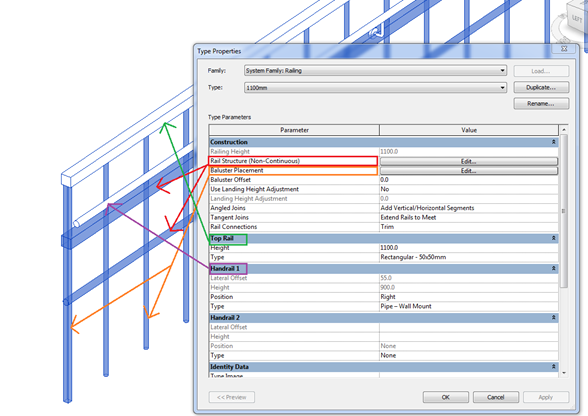
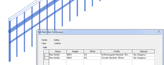
Rail
They are the horizontal elements.
You can add as many as you want.
Height> distance from the base.
Offset> offset in plan view.
They are created as sweeps using a Profile Family.
Profiles are loadable custom families that are nested in the railing system family. They have to be loaded into the project in advance.
Profile > you can add new profiles using Metric Profile-Rail family template.
There are two special rails that can be defined in railing families:
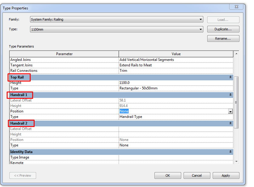
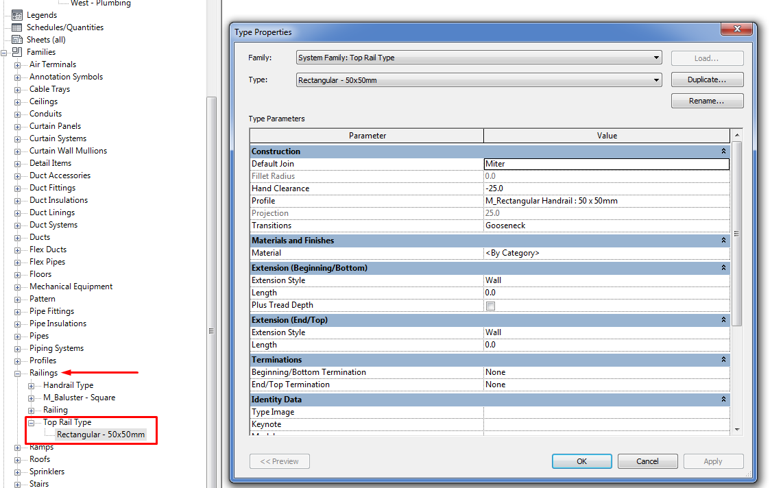
Top Rail. This is the upper element. It selected directly in type properties panel (not in the “rail structure” edition tool).
Top Rail is a system family that is nested into the Railing system family. To create different Top Rail types we will have to look for them under the “Family” section in the project browser.
Handrail. The same way as the Top Rail it is modified directly in type properties panel. It can be located to the right, left or both sides at a desired distance.
As Top Rail, Hand Rail is a system family that is nested into the Railing system family. To create different Hand Rail types we will have to look for them under the “Family” section in the project browser.
Railings can be created as free-standing elements or attached to hosts such as floors, ramps, or stairs.
Place on host
It’s mandatory to have a stair or a ramp to host the railing. They will adapt to the element the same way they do when you make the stair or ramp with the railing included.
- On treads. Railing will be supported on the treads.
- On stringer. Railing will be supported on the stringers.
Railing by sketch
This type of railings don’t need a host. You have to draw the path that will follow the element. By default, it is located in the plan of the level where you are drawing on.
However it is possible to assign a new host to the railing.
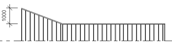
To achieve a sloped railing by sketch, it’s necessary to draw it by segments, always forming an unique loop not necessarily closed.
Draw the path. It will show up in the options ribbon with several parameters. There are three options once the sketch becomes a railing:
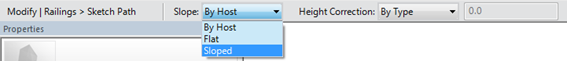
Slope> Sloped
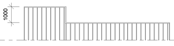
Slope> Flat
Slope > by host
Notice that these three options refer to the slope of the top rail. The base of the railing will remain fixed to the host.
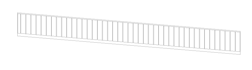
Tip: Model a railing on a curved sloped floor slab
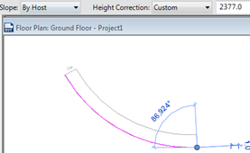
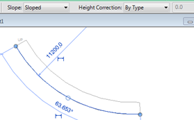
Draw the railing with the curved shape.
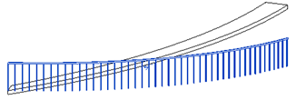
Edit the path, adding a really small segment at the end. You have to give a Height correction to this little segment, with the value of the height you want to rise. And, at the end, mark the main path as “Sloped”.
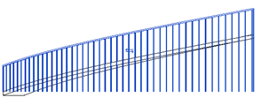
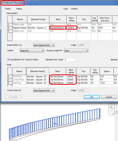
To achieve the railing to adjust to the base of the slab, we should modify the railing properties.
Edit Type> Balauster Placement> Regular Balauster>Base>Top Rail Element>base offset> “Railing height”
Tips & Tricks
Stairs and ramps are always architectural elements, never structural.
Joins between stairs or ramps with the floors in which them disembark require work to get them to fit their real constructive aspect.
Sometimes it’s advisable to model only the risers and treads of the stair and build a sloped floor or an in-situ component.
Remember to check the instance parameters of the stairs.
Remember to check instance parameters of components:
- Run: Begin with riser, End with riser, Location line
- Landing: Relative height
- Support (stringer or carriage):Upper/Lower end cut
Conclusion
Stairs, ramps and railings are complex elements that can achieve a high level of customization, this guideline explains good practices to configure them as we want, embracing the types of elements, the parameters that each type holds, and how to adjust their settings to the design we want.
Associated Files
- Families Guideline
Me podrian ayudar, como poner un soporte en posicion vertical de perfil de canal en el primer escalon y al mismo tiempo se conecta con el soporte que va a lo largo de los escalones. Saludos
Hola Alejandro. Probablemente tengas que usar una familia especial para el soporte inicial. Aquí te dejo una clase antigua del Autodesk University donde seguro que encuentras ideas para personalizar tu escalera. ¡Espero que te sirva!
Un saludo.