

Managing linked views in Revit
Managing linked views in Revit
Goals
The objective of this Guideline is to propose a workflow to achieve a consistent visualization of the base plans in all project documentation drawings when different companies are involved and/or several 3D models are available.
Requirements
- The user knows how to use Revit.
- The user has notions of producing graphical documentation (views and plans) in Revit.
Introduction
Sometimes we are confronted with complex projects in which several companies are involved, and in which each of them has a specific scope, for example: if it is to design a campus with several buildings, each of the buildings may be in charge of a different company. In order to carry out their part of the project, each of these companies will have to create one or more of their own geometry models to model their part of the architecture, MEP, structures, etc.
When this is the case, it is also common to have to generate documentation drawings that also show elements of models belonging to other companies or disciplines. In these situations, it is necessary to carry out an exhaustive work in order to control the correct visualization of each of the modeled elements. The problem is that there are many properties of these models that do not belong to us that we do not know how to control: view ranges, level of detail of the families, etc., and the visibility configuration that works for a particular model may not work correctly for another model.
To successfully manage these situations, we propose as a tool to ensure graphical consistency between models the creation of support views in each of the models of each of the contractors, linking them directly in the existing documentation models, instead of generating the visualization directly from the documentation model view. This way, if there are any visualization options to modify, it would only have to be done once in the master view.
View Linking Strategy
Due to the variability in the number of models, views, disciplines or phases depending on the project, there is no single way to approach the process of creating and managing linked views. However, in order to simplify the general approach we propose two main options:
Support views in each geometry model
As we have mentioned, if we have several models of the same discipline that have to maintain the same visualization; One option is to generate linked views in each of these models, controlling that the visualization is the same in all of them.
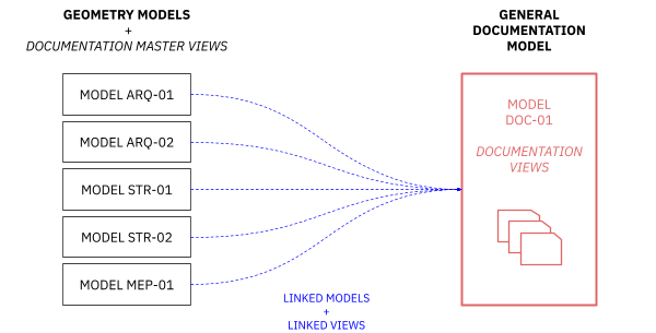
In this case, view templates are often used, but since they work on different models at the same time, there is a risk that they may be modified differently depending on the model, and a consistent visualization between models cannot be ensured.
Furthermore, this option involves a considerable workload, since you have to create, code, and edit each view in each model and subsequently link them one by one in each of the documentation views.
Intermediate support models
The second option, which we call “intermediate models”, is to generate a series of intermediate models that act as a bridge between the geometry models of each discipline and the general documentation file. These files are really blank files in which we will link all those models of the same discipline that have to follow the same visualization.
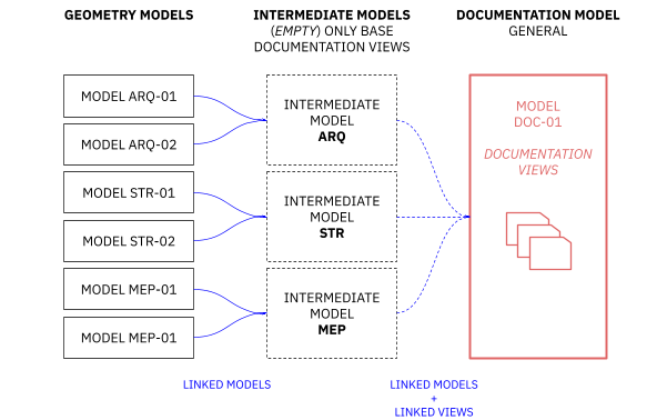
The possible disadvantage of this system is that we must generate more Revit models than in the first option, ensuring that they are correctly encoded and linked to each other. However, the good news is that there are fewer models to link in other disciplines' files.
However, in really complex projects, this option clearly has important advantages over the first option; it's much easier to ensure graphical consistency between the different models of each discipline, since a single view template governs over all affected models and does not need to be modified on a model-by-model basis. Besides, the number of linked views is greatly reduced, facilitating their management, since they must be linked one by one in the documentation model.
How to create linked views
First of all, it is necessary to analyze the models that contain modeled information. In the simplest cases, there will be a single model for architecture, another single model for structures, and another for MEP. But it could also be the case of having several models associated with each of the disciplines; To correctly manage these cases, we will add a series of intermediate support models, as we will see later.
Preparing the views to link
In order to correctly set up the view linking system, we should follow a series of general guidelines:
- Firstly, along with the rest of the disciplines, we will define the necessary representation guidelines, that is, the visualization criteria that the other disciplines need.For example: architectural floor plans may include specific shading depending on the type of pavement, either to make it more realistic or to explain its use; however, when we need to represent that same floor plan in a MEP drawing, we will be interested in the floors coming out white, otherwise the drawing would be unreadable.
- Once these criteria are established, those responsible for each model should be in charge of preparing these views for the other consultants on the project.
It is advisable to establish a clear organization of the project navigator, so that when generating these views they are stored in a section of the browser where everyone understands that they are not working views, and that they cannot be modified unless the person responsible for the visualization considers it appropriate.
- Additionally, a specific nomenclature must be defined, which clearly and quickly identifies which views the rest of the consultants will later have to link. This nomenclature will depend on the different variables that the project has.
For example: we must know if the project has phases or not, if the project has design options, if the project has different buildings that follow different visualization or levels, etc. It is essential to add in the name of the view the level to which it refers. It is recommended to name these views with a common prefix, so that they are more easily recognized, and that the level information is the suffix of the view.
The following is a proposal for naming this type of view.

- Once we have established the display criteria and have correctly created and coded our views, we can link them in our documentation files.
To do this, we must ensure two things:
- We have a documentation view created in our drawing model to link the created view to.
- We have previously linked the model in which we created the original view.
Linking views
To access the linked view management menu, we must go to the documentation view in which we want to link the base view. Once in this view we access Visibility/Graphics menu by clicking on 'VV’.
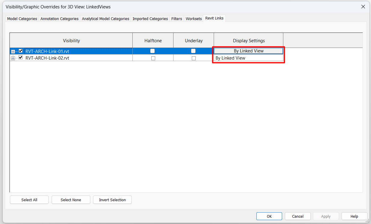
If the file we are working with has a link, a tab called “Revit Links” will appear. This tab shows all the links we have in our file. By default, all links always have the option “By host view” configured. This means that the parent view setting modifies the visibility of all links that have this option.
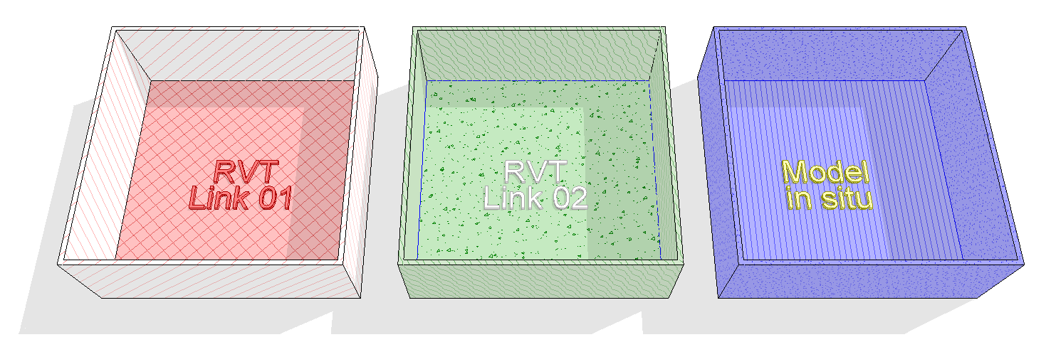
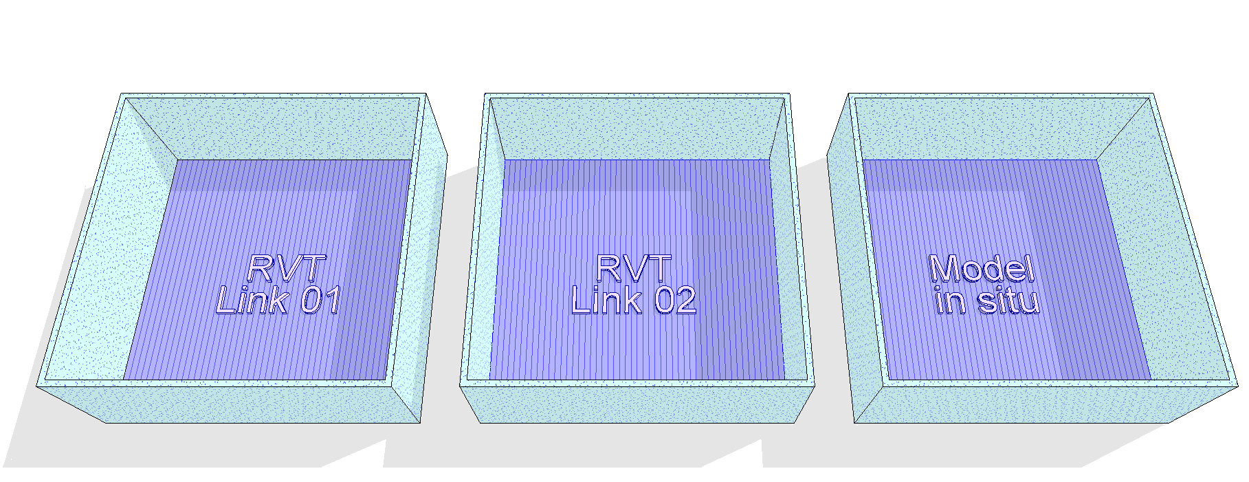
- In the image bellow, a sample model with three equal geometries, the first two are in links and the third in the insitu model. The host view modifies all elements by coloring them blue.
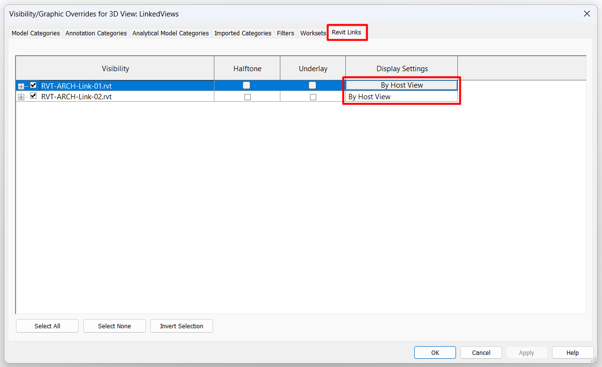
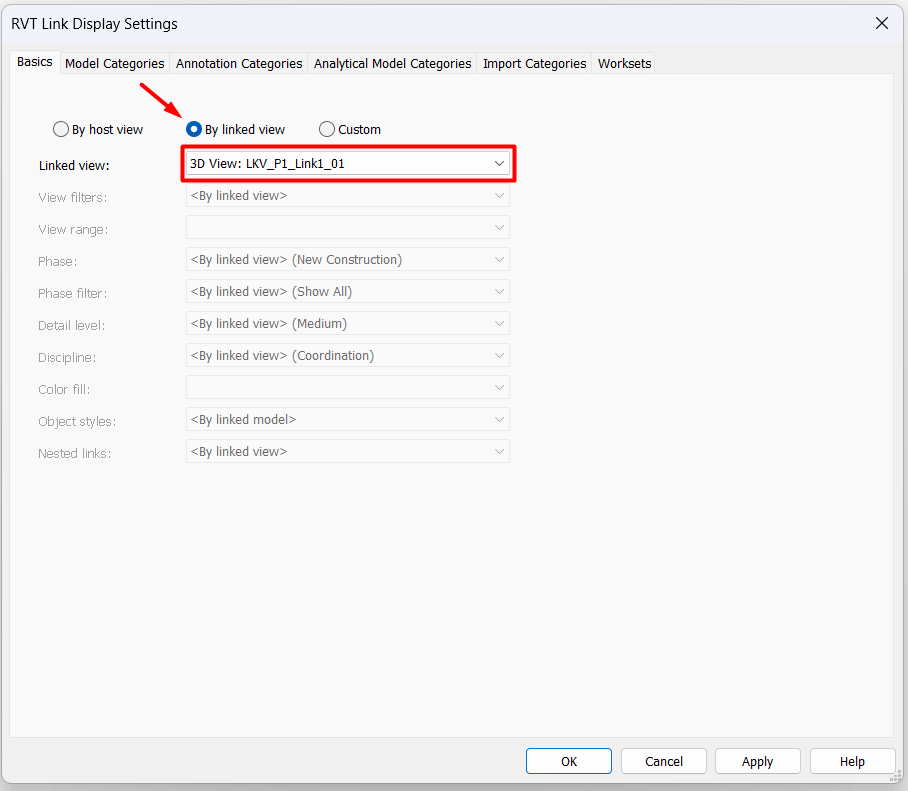
If we click on it, the visibility configuration menu for each link we have will appear. By clicking on the option “By linked view”, a drop-down menu will be enabled in the section “Linked view", this contains all the "linkable" views, that is to say, views of the same type as the parent view that are in the link that we are modifying.
In each view of the documentation file we can link one view for each Revit link that contains the view. That is, the same documentation view can have several linked views of different models.
By following these steps for each of the project levels, we will have established the base views for the documentation views. This process of linking views cannot be automated, it must be done one by one, so the fewer views we have to link, the less time it will take to do it.
- In the image, the same example as before, but the two links have been configured “By host view", this way, only the modeled elements "in situ” are kept in blue. The rest are colored according to your model configuration “host”.

Linked Views in Intermediate Models
In those cases in which we use empty intermediate models as support for our documentation views, the following must be taken into account:
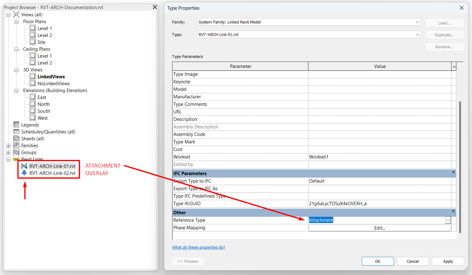
Geometry models must have aLink Reference Type as “Attachment” in the intermediate model. This can be checked by going to the Project browser navigator > Revit Links and double-clicking each link.
If the link is in “Overlap” mode, it will only be seen in the intermediate model, but when linking the intermediate model in the documentation model, the link will not appear.
Once the intermediate model is created with its linked models with reference type ”Attachment“, it will be necessary to proceed to generate the base views on this model in the same way as explained in the previous points.
The only difference between a view linked from a simple 3D model or an intermediate model is that with the latter it will be necessary to enable the option: “Nested links -> By main view” In the link display customization tab.
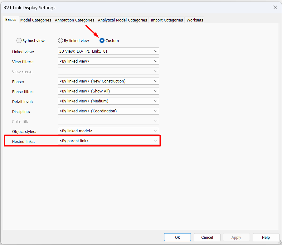
If this option is not selected, the customization of the view will not work, since it will refer to the intermediate model, and not to the models it has linked, and as mentioned above, that model is actually empty.
Linked View Properties
In general, the linked view looks as it was configured from the original model, regardless of what display options the documentation view has or whether it has any templates applied. However, there are some exceptions:
- Scale: It doesn't matter what scale the linked view is set to. This will always follow the scale properties of the view in which it is linked. This is a positive thing, since it is not necessary to make different linked views for each scale, but rather the view will adapt itself. The only precaution that should be taken would be in the case of adding labels or annotation elements in the linked views, since these are always displayed in the same size, they do not scale; therefore the strategy must be very clear when tagging in linked views.
- View range: It doesn't matter what level the documentation view is at. A view from any other level in the project can be linked, as the view range does not affect the linked view either.
- View types: Only a view of the same type as the documentation view in which it is located can be linked, for example, in a 3D view another 3D view can be linked, but not a plan view. Furthermore, you cannot link reflected ceiling plans in any case, not even by linking in another reflected ceiling documentation view.
- Halftone/Underlay: By activating these options in the link, the linked view does modify its display to Halftone mode or underlay mode, as selected.
- Custom style: The rest of the display options are not modifiable from the view options. To alter the display of the linked view, the “Custom” option must be selected.
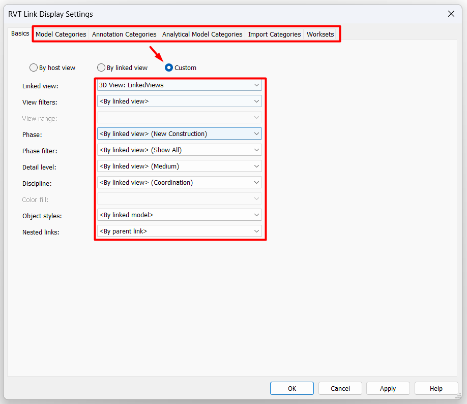
Within this option, practically the entire display of the linked view can be modified. We do not recommend modifying these options If what is intended is to have base views, since the interesting thing is that they always follow the same visualization, but it could be useful in some specific cases, such as, for example, not configuring two different views for Current State and Final State, but altering the phase or phase filter of the base view. Or another example, if you want to use the same view for several scales, it is possible that the level of detail does not work for all of them and you will have to modify it to see it in more detail in the zooms, and less in the general plans. Therefore, it is essential to establish the linked views strategy.
The most important thing we must keep in mind is that if we customize any of the display options of the linked views, they will no longer respond to the initial configuration. This is especially sensitive in the case of filters, if we set them to custom option, all the filters that were applied to the linked view will disappear and we will have to configure them again, since the filters of the linked view and those of the documentation view are not compatible.
Conclusion
As projects become more complex and more agents involved in the design and documentation process of a project, we need tools that allow us to ensure minimum graphic consistency in all our drawings. Otherwise, each contractor could end up applying their own graphic criteria and end up making the project unintelligible. It is in this context where linked views appear as a very interesting tool, since they make it easier for a small group of people to manage the overall visualization of the project.
A good linked view management process implies having a coherent nomenclature established, a linked files strategy where each agent is clear about its role and scope, and correct coordination between the different teams to know what is going to be seen in each place and how it is going to be seen.
As we have seen, it is a process that has its limitations, since it involves a lot of time in its initial configuration. However, if the project is well planned, it will soon be seen that this initial time investment is clearly compensated during the project, by clarifying and simplifying the creation of the graphic documentation of the project.
Tips and tricks
- Intermediate models do not allow you to customize elements of just one of the links they have nested, but it has to be all of them at the same time. To turn off a specific link, it would have to be done through workset management, and to apply filters to only one of the links, the intermediate model system cannot be used.
- Even if the “Halftone” option is applied to one or more of the links in the linking view of the intermediate model, once that view is linked in another model, the halftone gradient applied will be according to the halftone setting of the model where this view is linked, not the gradient given in the linked view.
- If a link is unloaded, or within a closed subproject, it will not be possible to access its linked views either, so the models have to be properly loaded and active.
- Every time a view is linked, if the weight of the models is very large, or if the intermediate models option has been used, the computer usually takes a few seconds to incorporate the new visualization and it can be a very slow and cumbersome process. If this happens, the recommendation in this case is to select all the linked views by accessing the graphics display options of a view from the project browser, without opening it, and in the meantime, have open in the main screen a legend, a planning table or an empty plan (some type of view that does not contain modeled elements). In this way, Revit will not be processing all the new visualization each time the base views are selected.
- If a link is unloaded and removed from the model, the linked view associated with it will also be removed, even if it is later relinked. Therefore, it is not recommended to delete links from models that contain linked views. It is always better to reload the model in case you want to update changes or “download only for me” when you do not want to see the model for any reason.
- Even if the name of the linked view is changed, it is still recognized by the documentation view, so there is no risk if a naming change needs to be made.
- We cannot view areas that are in a linked file except through Linked Areas views.