
Bridges: from Civil Software (Civil 3D, Istram…) to Revit
Adaptive Sections on Real Layout
Since few years ago, big efforts have been carried out to perform bridges and viaducts in Revit’s parametric approach. Improvements have come after following different strategies, some of them can be seen in this Autodesk Univeristy Post by Matthias Stark and Lejla Secerbegovic.
Another sign that the times are changing: there was a specific Bridge workshop on Algomad 2016, in which I could share our work together with Javier Giménez, a structure engineer at Fhecor
State of art
Today we can currently place adaptive elements on points given their (x,y,z) coordinates and generate a 3D object via extrusion, sweep or loft. This is good enough to create objects in Revit and add parameters to them. However (there is always a however) the automation grade of this strategy is somehow constrained:
- In theese workflows Dynamo is reading points. We may regret this if we need the actual layout when placing additional elements in the bridge. This will happen if the kilometer of the element to insert is different than those from the layout software.
- This means we will need the (x,y,z) for columns, abutments, etc. or to forget about clothoids and work with splines. Nevertheless, changing the axis layout of the board will leave these other elements literally out of place if we don’t re-extract (x,y,z) from civil software.
- Depending on the adaptive points that we choose, we may create too particular Dynamo definitions. This will surely happen if the chosen adaptive points depend on section shape or brigde length.
- Once sections are placed, we have little range to perform changes in Revit, section geometry may be constrained too much by adaptive points and too little by Revit parameters
Our approach to bridge modelling or how we deal with that
To solve those issues, our Dynamo definition is commited to theese two targets:
- We completely re-generate the bridge longitudinal axis in Dynamo actually by reading the curves parameters from civil layout software (Istram, Autocad Civil 3D, etc.). This means we care about azimut, radius, clothoid parameter and Kv in addition to (x,y,z) coordinates of the start/end points.
- Our adaptive points lay on the real layout axis. We use them to define just insertion point and orientation of section profiles. Our adaptive points don’t drive section geometry.
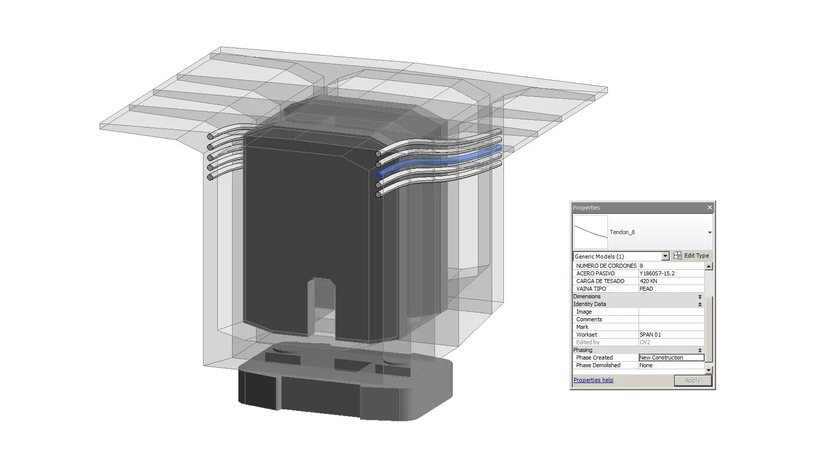
- Section geometry is driven by parameters. Thus, we can change the section family without changing adaptive points. That means the same Dynamo definition is useful for road, rail or footbridges.
So, the input to our definition is the actual axis (from Civil 3D,Istram…) plan and elevation output and the list of the section geometry parameter values (may be a spreadsheet from structure engineering team). This is how our workflow looks like, please open the image in a new window if needed):
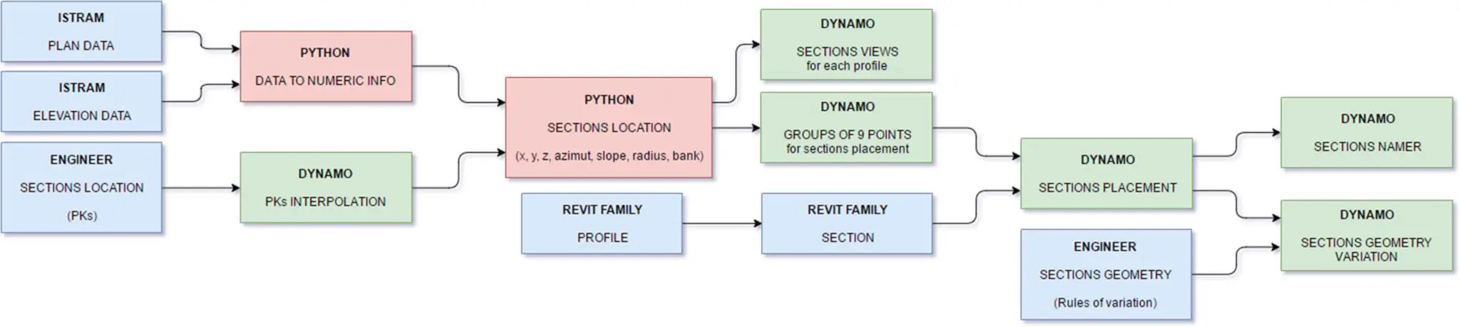
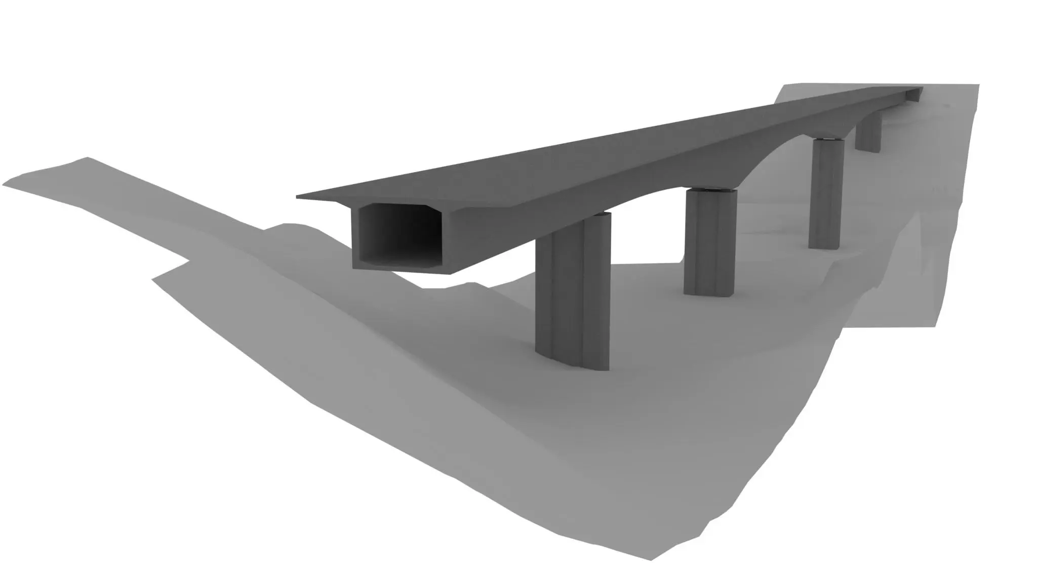
Thus, everytime that the axis layout changes, our Revit Bridge changes accordingly, and columns are replaced (since now they are referred by PK and not x,y,x coordinates). Furthermore, we can change the section families without changing adaptive points and drive element geometry from Revit (if we want to)
See you next Post!