
Civil projects and BIM Methodology II
Part II: Tunnel modelling case
Among the available BIM tools, Revit (editing software) and Dynamo (visual programming software on Revit) will be used below. The authors consider that it is not the only software available to make this model, and it is shown only as an example.
In this case, a flat tunnel on a circular curve is considered. If else, the user will have to program the corresponding layout equations.
1.1 Design alignment data
Initial data consists of alignment data of the baselines in which the tunnel will be modeled. This is the information required for each baseline:
- Baseline starting location, azimuth and slope.
- Curve radius, or initial spiral radius.
- Vertical Alignment parameters.
This information is to be obtained from the layout software.
1.2 Baseline Modelling
The introduction of this data in Dynamo (Revit programming tool) can be done with the following options:
- Manual: The introduction is simpler, but requires to be updated manually if the alignment parameters are changed (see Figure 1).
- Automatic: An automatic reading of the alignment parameters from civil design output can be programmed, typically in LandXML format. This option is complex, but allows an automatic update of the model in the event of alignment changes.
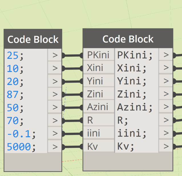
Figure 1. Example of manually entering plot data for a curved alignment.
The civil design equations are programmed in Dynamo, using the usual mathematical tools (Figure 2).
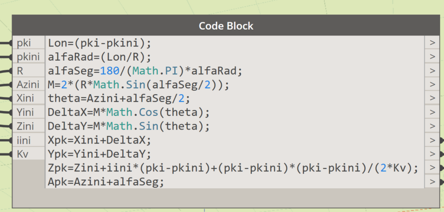
Figure 2.Example of civil design equations (curve and slope alignment) in Dynamo.
By connecting the civil design equations with the list of stations of each tunnel element, the baselines are restored in Revit using Dynamo. The list of stations can be read from a spreadsheet using the corresponding Dynamo commands (Figure 3).
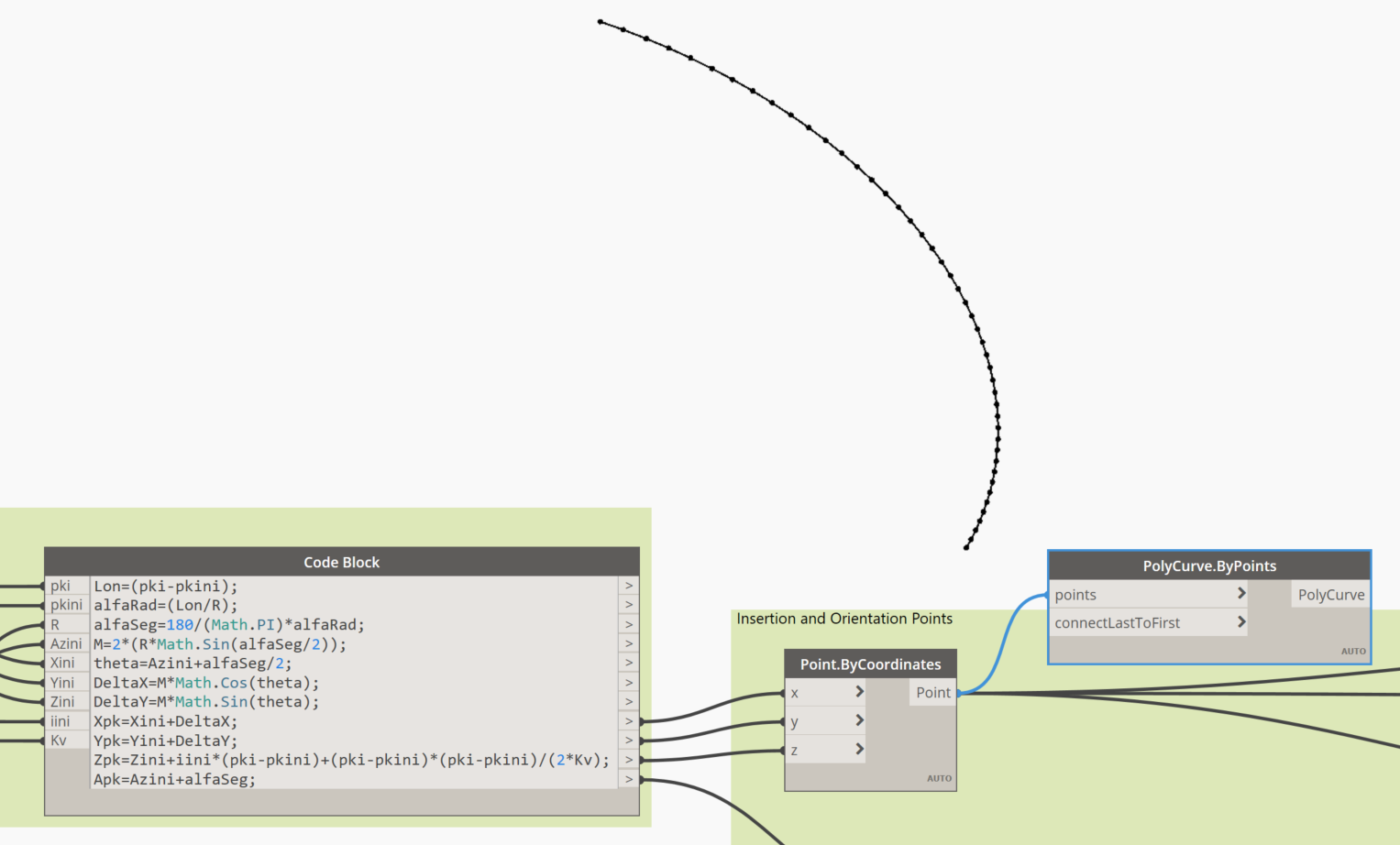
Figure 3. Creation of the baseline in Revit from the civil design equations.
1.3 Family creation
Elements such as segments, rings, entrances, injection elements, bolts and reinforcement trusses can be easily modeled in BIM software. They do not have any special feature in comparison to any other structural objects. However, when planning its creation, the following must be taken into account:
- The insertion point in the model must be consistent with the stakeout point of the previously modeled baseline.
- Elements must have the ability to rotate in plan, using an azimuth parameter.
- Elements must have the ability to rotate in elevation, using a slope parameter.
- Elements must be able to rotate on their longitudinal axis (roll), simulating the position of the k segment. A k segment position or angle parameter can be used for this purpose.
The following shows the edition of a tunnel ring including its k segment (Figure 4) and the parameterization of the family (Figure 5).
Figure 4. Example of a ring family in Revit, with the ability to rotate in plan, elevation, and longitudinal axis.
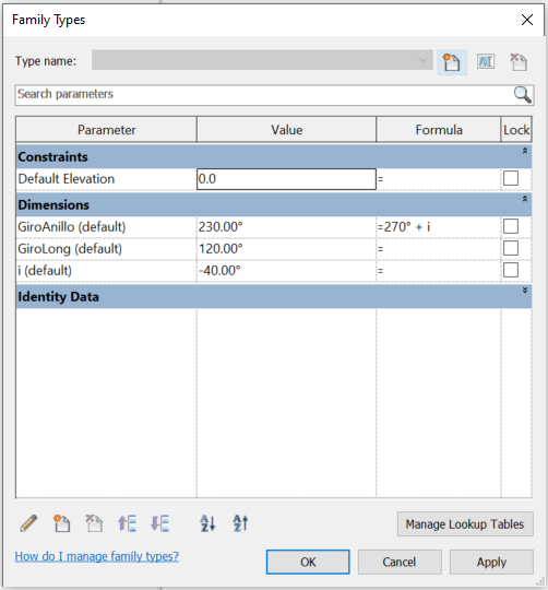
Figure 5. Parameterization of the ring family. Note its simplicity. Only 3 rotation parameters are required, one for each axis.
1.4 Creating instances
Instances will be created according to evaluated stakeout stations. Civil design equations programmed in Dynamo will transform the linear station parameter to global x,y,z coordinates. (Figures 6 and 7)
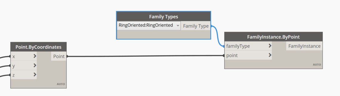
Figure 6. Instance creation in the model according to the previously evaluated stations.
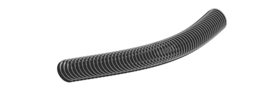
Figure 7. Segments placed on the model. Note that the azimuth, inclination and roll of each segment still lack the correct values.
1.5 Modifying parameter values
The last step in tunnel modeling is to assign the azimuth, slope and roll parameters to each object. The first two have been calculated in Dynamo using the civil design equations (Figure 8). For roll, you can read the spreadsheet in which this data is stored, or the alignment output file (Figure 9). With this process the tunnel achieves its final geometry (Figure 10).
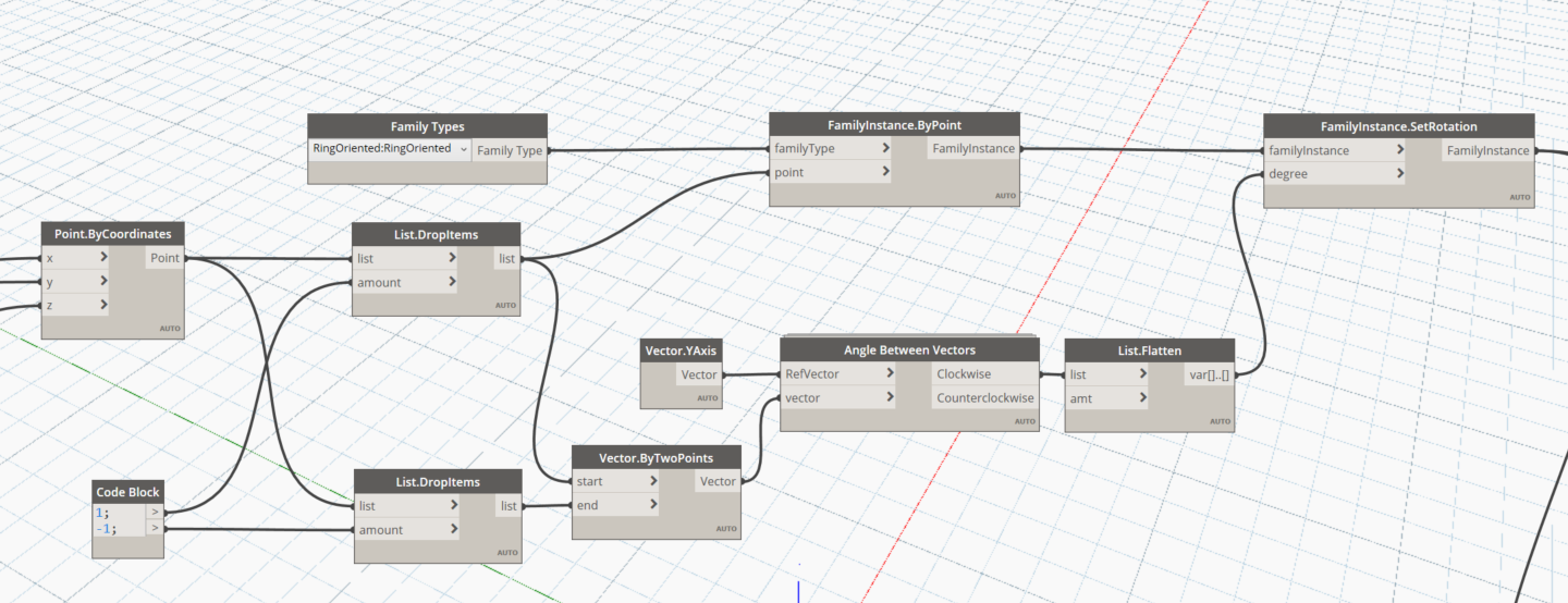
Figure 8. Command used in Dynamo to set the plan rotation, assigning the azimuth of the corresponding station.
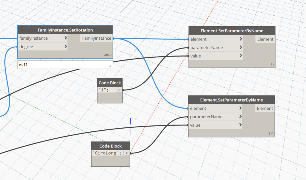
Figure 9. Command used in Dynamo to set slope and roll.
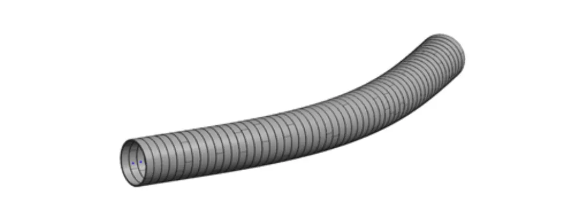
Figure 10. Final geometry of the tunnel, the segments have been placed and oriented using the corresponding parameters.
1.6 Bottomline
This is a simple demonstration case. However, this same process can be replicated for the placement of the rest of the tunnel elements.
For example, for those elements that present setbacks with respect to the stake out axis of the tunnel, local coordinates can be used to help fix their position. These coordinates would be introduced into the model with the same logic as that used for longitudinal rotation.
These specific actions must be considered when dealing with roads or railways structures modelling:
- Program the BIM modeling tools to be able to take advantage of the information from the civil design software output files.
- Standardize the information sources used to feed the BIM models. That applies to the spreadsheets used by the structural analysis teams.
- Generate a library of three-dimensional content that is self-documenting, that is, that contains 2D objects for efficient drafting procedures.
- Program the BIM modeling tools to automate the creation of plan drawings.
- Program the BIM modeling tools to automate the extraction of measurements.
- Use of collaborative tools for task management, clash detection, issue management and document management.
- Training in the BIM contractual framework.
- Preparation of the BIM management framework, based on the BIM Execution Plan (BEP).
- Develop of pilot projects to establish performance metrics.
If you have not yet read the first part of Civil Projects and BIM Methodology: Context and Challenges, you can read it here.
Author: Oriol Vidal