

3D Reinforcement
Configuration and Workflow
3D Reinforcement
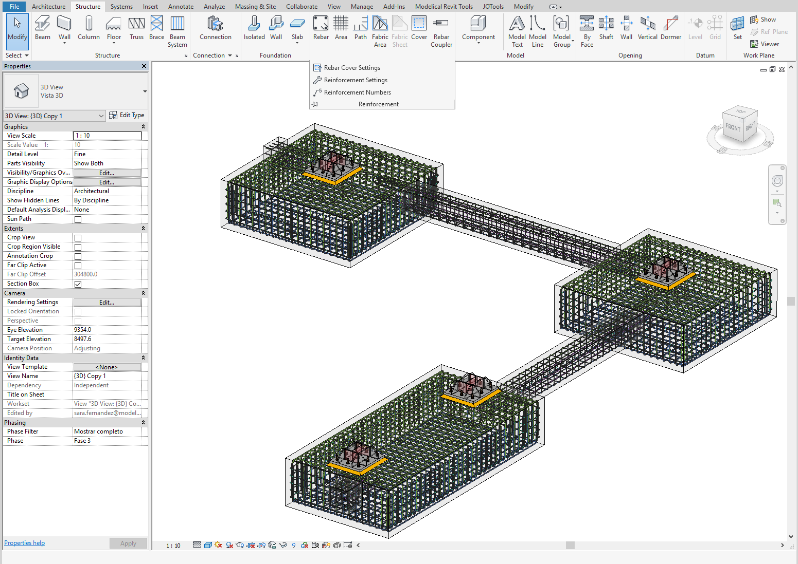
Objectives
Understand how to model and document 3D reinforcement.
Prerequisites
- User will be using Revit 2015 or more recent.
- User has basics skills in structural modelling.
- User has notions about how parameters work in Revit.
Description
When the project requires the modelling of reinforcement of structural elements, Revit offers an intuitive way to model and represent such reinforcement. This guideline explains the general settings and procedures to perform a successful modelling process.
Procedure
Settings
It is important to ensure that the entire geometry of the model is set to the level required to accommodate the assembly.
The elements to be assembled must be attached to the other adjacent concrete elements.
Trying to work as much as possible with Level of Detail "Coarse" improves the handling of the file considerably.
Visualization
It is recommended to generate a working view to model the assembly.
The visibility must be set so that bars (Structural Rebar) are displayed as desired.
Keep in mind that bars have a special visibility configuration that is accessed by selecting the bar itself and in the Properties window, Graphics:
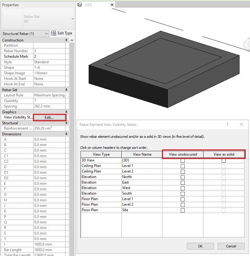
In this window we choose for each view 2 possibilities:
- View unobscured. To see the bars axis through the element that contains them.
- View as solid. To see the bars complete solid through the element that contains them.
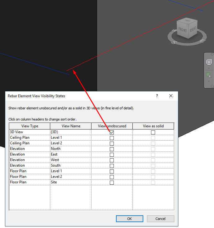
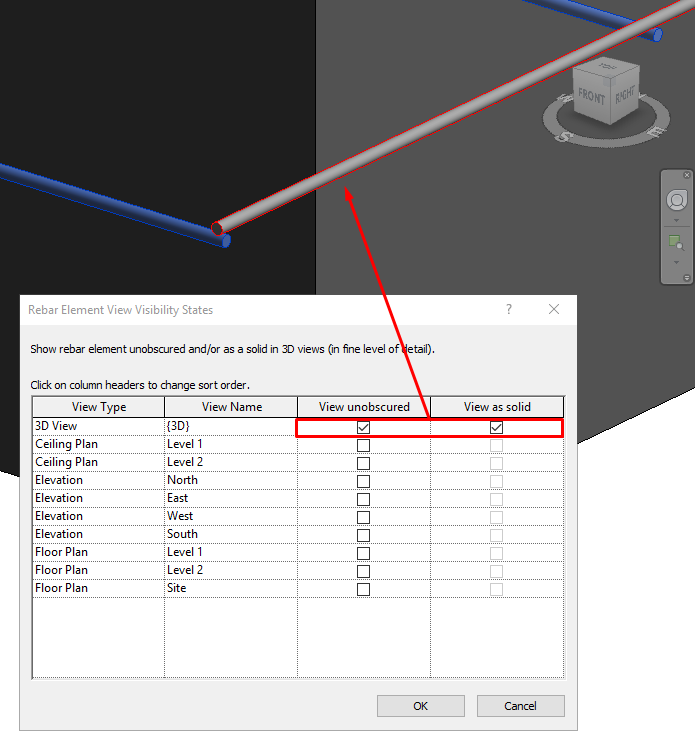
As these two parameters cannot be controlled by Template (since they apply to each bar) a possible solution to see them can be to modify the transparency of the elements and thus the bars are equally seen if the "unobscured" option is selected or not.
Bars work just like any other element regarding their visibility. Its configuration can be changed generally by means of the Object Styles or by View.
Basic Elements
In Project Browser / Families / Structural Rebar we can find the 3 classes of basic elements to reinforce in 3D in Revit: Rebar Bars, Rebar Hooks and Rebar Shapes.
Rebar Bar. Bars are a system family and therefore the creation of types and modification of properties must be done in the model.
Rebar Hook. They are also a system family.
Rebar Shapes. When a bar is inserted, Revit automatically associates a Rebar Shape with the element. The shapes themselves are components and they are edited out of the model and then loaded into it.
If a bar is created using the "sketch" option and its shape does not correspond to any of the loaded shapes, Revit automatically generates a new rebar shape.
Rebar bars
Type Properties
Bar Types are related basically to the different diameters. They type properties are:
Deformation.
Rounding Overrides.
Subcategory: it’s very important to create and select the appropriate subcategory. This allows us to better control visualization and export to DWG.
Material.
Dimensions Parameters.
- Bar Diameter: we can put the real one and call the family by the nominal one.
- Standard Bend Diameter.
- Standard Hook Bend Diameter.
- Stirrup / Tie Bend Diameter.
- Hook Lengths: Opens a table where the length of the hook is automatically calculated based on the Multiplier, see: REBAR HOOKS.
- Maximum Bend Radius.
Identity Data: common parameters.
Instance Properties
Construction: Partition, Rebar Number, Schedule Mark, Style, Shape, Shape Image, Hook at start, Hook at End, Rounding Overrides.
Rebar Set: Layout rule, Quantity, Spacing,
Graphics: View Visibility States.
Structural: Reinforcement Volume.
Dimensions.
Identify Data.
Phasing.
Rebar hooks
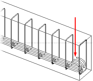
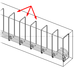
To define a type of Hook or modify any of the loaded: go to Project Browser / Families / Structural Rebar / Hooks.
Such hooks will have the following properties: Style (Standard or Stirrup/Tie), Hook Angle and Extension Multiplier. Depending on the value of Extension Multiplier, the lengths of the hooks are calculated in the type properties of the Rebar Bar.
Covering
Covering is controlled by instance parameters, by default, all the elements that can be reinforced contain them. Those categories of elements that can be structural or not, such as Walls or Floors, will only show the covering parameters if they have the "Structural" option selected, whereas a Structural Foundation always has those parameters enabled.
In the Structural tab, the Reinforcement panel opens a drop-down to select Rebar Cover Settings and create the Cover types that we consider. Then we can apply them to the previous parameters.
Placing Bars
Check whether the option of integrating Hooks is correct. On the Structural tab, the Reinforcement panel opens a drop-down where you can select Reinforcement Settings. There we can select or not: "Include hooks in rebar shape definition".
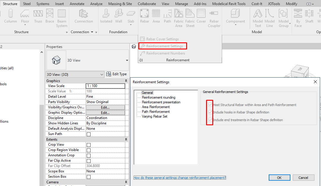
This must be defined before placing the first bar, later it CANNOT longer be changed.
To place a bar, the procedure is:
Find the right view to place the bar. (Check that the visibility settings allow you to see them). Releases previous to 2017 only allow to place reinforcements in floor plan and elevation views, not in 3D.
Go to Structure tab, Reinforcement panel, Rebar tool.
At that moment in the property bar already has been selected a type of bar, check if that is the one we want. Shape is an instance parameter, check that is the one we want. However we can also change it once the bar is created.
To create the bar we must look at the options selected in the Modify / Rebar Place tab that has been opened automatically. There are two parts: Placement Plane and Placement Orientation. We approach the item and the bar is automatically created. With the Space Bar we can modify the placement. From here we have several options.
Edit Constraints: The constraints are created automatically and indicate how the bar behaves in relation to its "host" and the rest of the bars. It is important to define them well to ensure that if a bar is moved or modified the rest of adjacent bars will be repositioned well. The first bars to be placed should be "to Cover".
Rebar Set. The bar can be Single or belong to a Set. It is used to generate a grid of bars indicating number, maximum space, etc. Once created they behave as a set.
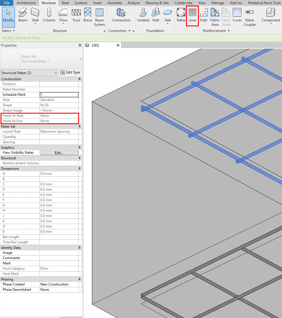
Note that the reinforcement created with the tool Area does not allow to place Hooks. This tool is oriented to modelling welded meshes, which constructically don’t incorporate them.
Annotation
Bar annotation families are a combination of "labels" referring to the different parameters of the bars.
Multirebar annotations can be edited and moved. Its dimension line and text position can be modified.
Conclusion
This guideline explains general settings and procedures to model Structural Rebars. It covers key file settings, visibility settings and modelling sequence and parametrization of rebars and their hooks.