

Architectural Floors
Operation in Revit
Architectural floors
File: OPE_Architectural Floors
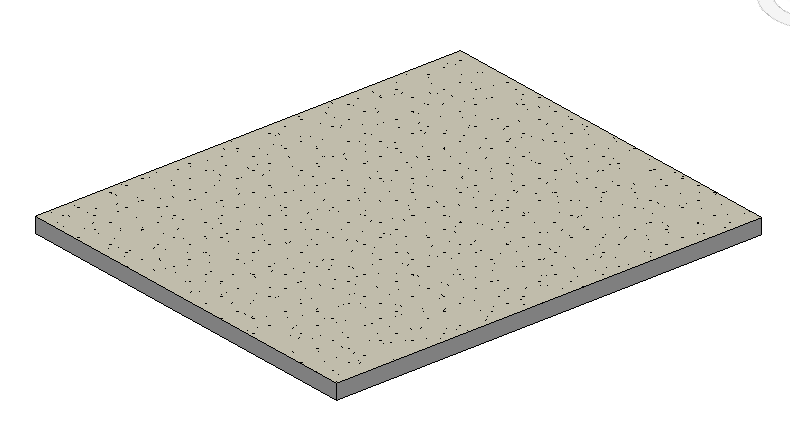
Objectives
- Be able to create a new floor, understanding all its properties.
Prerequisites
- Datums must be created before starting this guideline (levels, grids, reference planes).
Description
Floors are a system family. This means that they are created and modified within the model itself. There are not any external wall families to be loaded into the model. Floors can have several types within the family.
Procedure
Create a new floor
Creating floors can be done from the Architecture Tab. There are two possibilities from the floor tab: Architectural Floor or Structural Floor. They both belong to the same category but Structural floors have the “Structural” checkbox checked, meaning that they have some analytical properties for structural analysis.
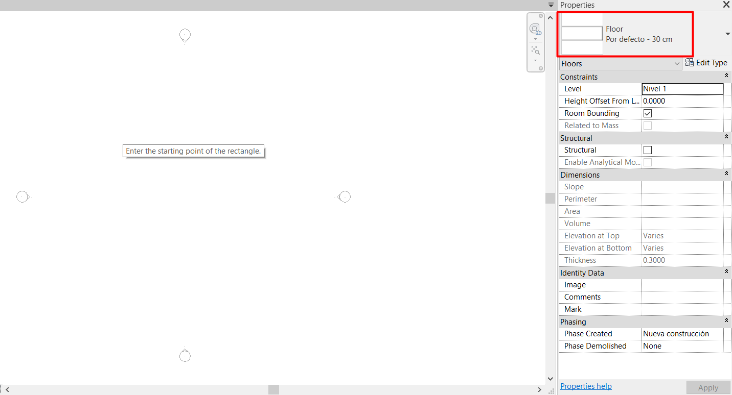
Before modeling the floor, it is important to choose the floor type from the Properties tab.
Create a new floor type
When creating a new floor type, it is recommended to duplicate an existing one. This is made by clicking on "Edit type" under the floor selector in the properties panel and later in "Duplicate".
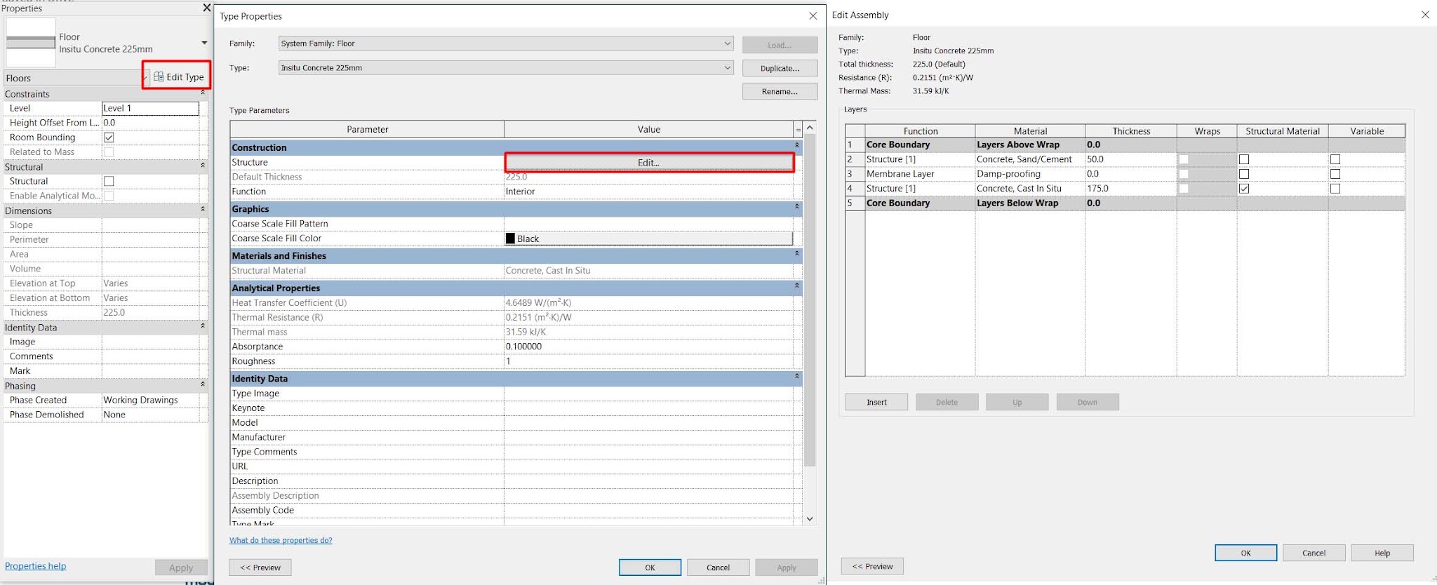
Within the type properties of a floor, you will find the Structure cell to define the floor layers. In a similar way to the walls, floors can be composed of several layers. From the structure window, it is possible to:
- Add, remove and arrange layers
- Define the function of the layer
- Define the thickness of the layer
- Define the layer material.
- Check whether it is a structural material or not
- Check if it is variable
Layers within the core boundary rows will be for the core elements of the floor and layers above and below those rows will be used for the finishes materials. Assigning materials to the layers can be useful for quantity takeoff purposes. By clicking the Preview button, a window will pop-up to display a representation of the floor layers.
Floor modeling
- Floors are modeled from their perimeter, which is extruded to contain all the layers defined at the floor structure.
- They are located at a certain level. The direction of this extrusion goes from the associated level to down.
- They may have an offset distance from the Level. This is controlled through the “Height Offset From Level” parameter.
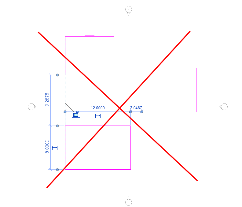
- Floors must be composed by a single contour perimeter. It is a bad practice to have a floor composed of several contours.
Properties
Type properties
Construction
- Structure Is the layer configuration of the floor type.
- Default Thickness: Indicates the thickness of a floor type, which is determined by the cumulative thickness of its layers.
- Function: It offers several possibilities, it can serve as a method of schedule classification. If you are going to use your model for energy analysis it must be watched closely because it affects their behavior in the analysis.
Graphics
You can choose floor shading configuration for those views where the floor is seen sectioned and the view level of detail is set to Coarse:
- Coarse Scale Fill Pattern: specifies a fill pattern for a floor in a coarse-scale view.
- Coarse Scale Fill Color: Applies a color to the fill pattern for a floor in a coarse-scale view.
Materials and Finishes
- Structural Material: it allows to choose the structural material. If none of the layers of the floor has enabled the option to "Structural Material" this box is inactive.
Analytical Properties
- Heat Transfer Coefficient (U): It is automatically filled according to the materials from the floor structure layers.
- Thermal Resistance (R): It is automatically filled according to the materials from the floor structure layers.
- Thermal mass: It is automatically filled according to the materials from the floor structure layers.
- Absorptance: A measure of a building element's ability to absorb radiation, the ratio of radiation absorbed to the incident. The default is 0.1.
- Roughness: An index value from 1-6 (where 1 is rough, 6 is smooth, and 3 being typical for most building materials) used to represent the roughness of a surface for the purposes of determining values of air film resistance in many common thermal calculation and simulation tools. The default is 1.
Identity Data
- Type Image: To add an image of the type
- Keynote: To add or edit the floor keynote.
- Model: The model type of the floor
- Manufacturer: The manufacturer of the flooring material.
- Type comments: Comments about the floor type. This information can be included in a schedule.
- URL: a link for a manufacturer web page
- Description: Provides a description of the floor.
- Assembly Description: Describes the assembly based on the assembly code selection. This is a read-only value.
- Assembly Code: Uniformat assembly code selected from a hierarchical list.
- Type Mark: A value to designate the specific floor. This value must be unique for each element in a project.
- Cost: Cost of the flooring. This can be included in a schedule.
Instance properties
Constraints
- Level: is the reference level for the floor. It’s always aligned with the upper face.
- Height Offset From Level: this is a distance that can be added to the floor to modify its height in relation to the level.
- Room Bounding: It indicates whether the floor is bounding a room or not.
- Related to Mass: Indicates the element was created from a mass element. this is a read-only value
Structural
- Structural: If this option is not selected the rest of the structural options are disabled. For those whose discipline is set to "Structural", only the floors with this option selected will appear.
- Enable Analytical Model: to enable the structural analysis of the floor.
Dimensions
- Slope Angle: Changes the slope-defining lines to the specified value, without the need to edit the sketch. The parameter initially displays a value if there is a slope-defining line. If there is no slope-defining line, the parameter is blank and disabled.
- Perimeter: The perimeter of the floor. This is a read-only value.
- Area: The area of the floor. This is a read-only value.
- Volume: The volume of the floor. This is a read-only value.
- Elevation at Top: Indicates the elevation used for tagging the top of the floor. This is a read-only parameter that reports different values for sloped planes.
- Elevation at Bottom: Indicates the elevation used for tagging the bottom of the floor. This is a read-only parameter that reports different values for sloped planes.
- Thickness: The thickness of the floor. This is a read-only value unless a shape edit has been applied and its type contains a variable layer. When the value is writable it can be used to set a uniform thickness of the floor. The entry can be blank if the thickness varies.
Identity Data
- Image: an image can be attached.
- Comments: comments can be added for further explanations or classification.
- Mark: A user-specified label for the floor. This value must be unique for each element in a project. Revit warns you when the number value is already used but allows you to continue using it.
Phases
- Phase Created: The phase when the floor was created
- Phase Demolished: The phase when the floor was demolished.
Floor scheduling
It is convenient to create floor schedules for controlling them. With alphanumeric data, you can quickly control their correct placement and characteristics. All changes made in the table will be reflected in the model and vice versa.
Naming convention
It is important to follow a defined order to name the different types of floors created. Normally, there will be a preset naming convention in the BEP from the project to follow. For instance, here is an example of naming convention for Architectural Floors:
Project_Company_Discipline_Category_Code or material_Description_Dimension
EJ: AKS_MOD_ARC_FL_WOOD-01_WoodFloor_30mm
A correct nomenclature is very important since types are organized ALPHABETICALLY, and therefore we are interested in materials to appear together.
Tips & Tricks
- Floors from an entire Level can be copied using Copy and Paste: Aligned to Selected Levels. You can copy to several Levels at once.
- In order to avoid repeated floors with different names, it is important to define the floors to be used in the project and load them into the project template. With this way, we avoid that people use the same floor with different names or materials.
Bottom-line
Floors are one of the main components in the architecture, so it is really important to control them properly and to know all its properties.