
Complex Families in Revit
Advanced modeling and Configuration
Complex Families
File: OPE_ComplexFamilies
Objectives
- Complete the guideline of Basic Families.
- Use formulas to drive parametric values.
- Learn how to plan a family.
- Use nested families to control the parameterisation of the family.
Prerequisites
- User is familiar with Revit 2015 or more recent.
- User is comfortable creating a new family from a template file.
- User is comfortable using reference planes.
- User is comfortable creating basic dimensional constraints and parameters.
- User is comfortable building the standard geometric forms such as extrusions, blends and sweeps.
- User is comfortable adding family types and flexing the model.
Description
This guideline explains how to address the settings of complex Revit families, embracing the construction of a parametric skeleton, up to hosted families.
Procedure
Before creating a family in Revit, particularly if it is not straightforward, it is recommended that you follow the following process:
Planning
In order to achieve optimal results it is recommended that you plan the layout of your drawing prior to using Revit.
- Analyse the parametric behaviour of the family. Establish how the data is related.
This can be achieved by sketching on paper.
- Secondly, in conjunction with step one, it is important to collate relevant information beforehand, such as dimensions, materials and number of family types. In doing so, the family parameters and their related formulas can be clearly identified.
- Finally, it is important to establish if a family should be split into several families and understand how many families are required in order to solve the parameterisation of any given family.
Family Template
Before creating a new family, it is important to choose the appropriate family template. The template file is made up of two basic properties, which are crucial during the process: category and hosting behaviour. The template also offers many less obvious settings and behaviours that can also be inherited into a family.
Table 1: summary of categories and behaviours.
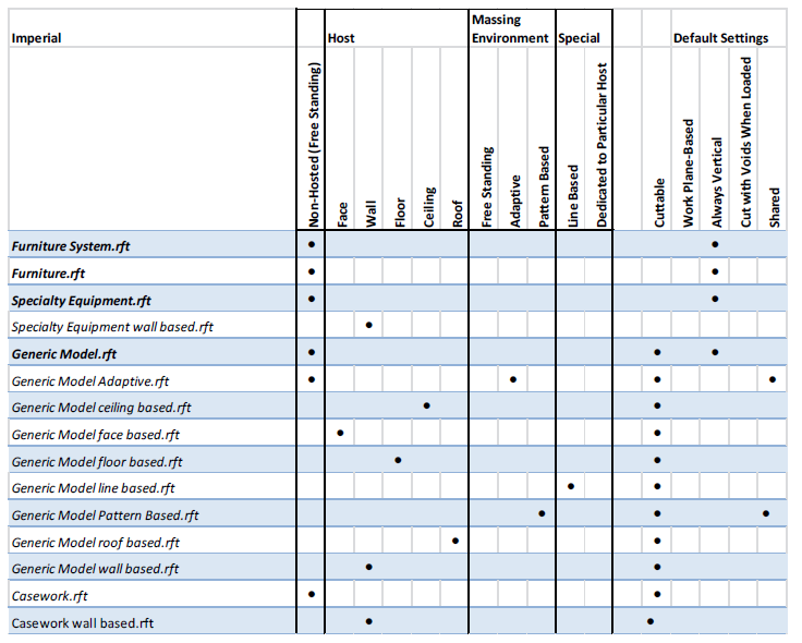
Category template
When planning a family, it is important to understand the settings that a template file contains. The generic model template is often chosen as a go-to option, given that it is possible to change the category at a later stage.
Whereas this option works in most cases, it is however, not fail-safe, and therefore it is not recommended as a workflow.
Family templates contain special features for each category, and determine the behaviour of each element. It is for that reason that the correct family template should be established at the beginning. For example:
- Structural column templates have two reference levels.
- Structural beams have two location points.
In the event that one of the above categories from a generic model template needs to be changed at a later stage, their respective, special features (two reference levels, two location points) will not be available, and as a result, the families will not behave as they should, once they are loaded into the project model.
It is important to choose the right template from the outset in order that the subcategories which are added to “object styles” and the “cuttable” behaviour are clearly determined by the chosen category. By changing the category, the subcategories and object style settings will be reset.
Of course Revit does not have templates for every single category, or the item you are creating might fit loosely into more than one category. But:
If the template for the category you need is available, choose it. There is a good reason for the template to exist.
If the template for the category you need does not exist, then choose another category template, the one that best fit for the Family that you are creating. You can change category later.
Hosting behaviour
The hosting behaviour cannot be changed later.
There are basically three options here: to choose the exact host you need (for instance “Wall based”), to choose a freestanding template (one that does not require a host) or use one of the Face-Based or Work plane options. A common practice is to use Face or Work Plane Based in lieu of Wall or Ceiling based. This keeps the family more flexible and makes it less likely to become invalid should its host go missing in an update to a linked model.
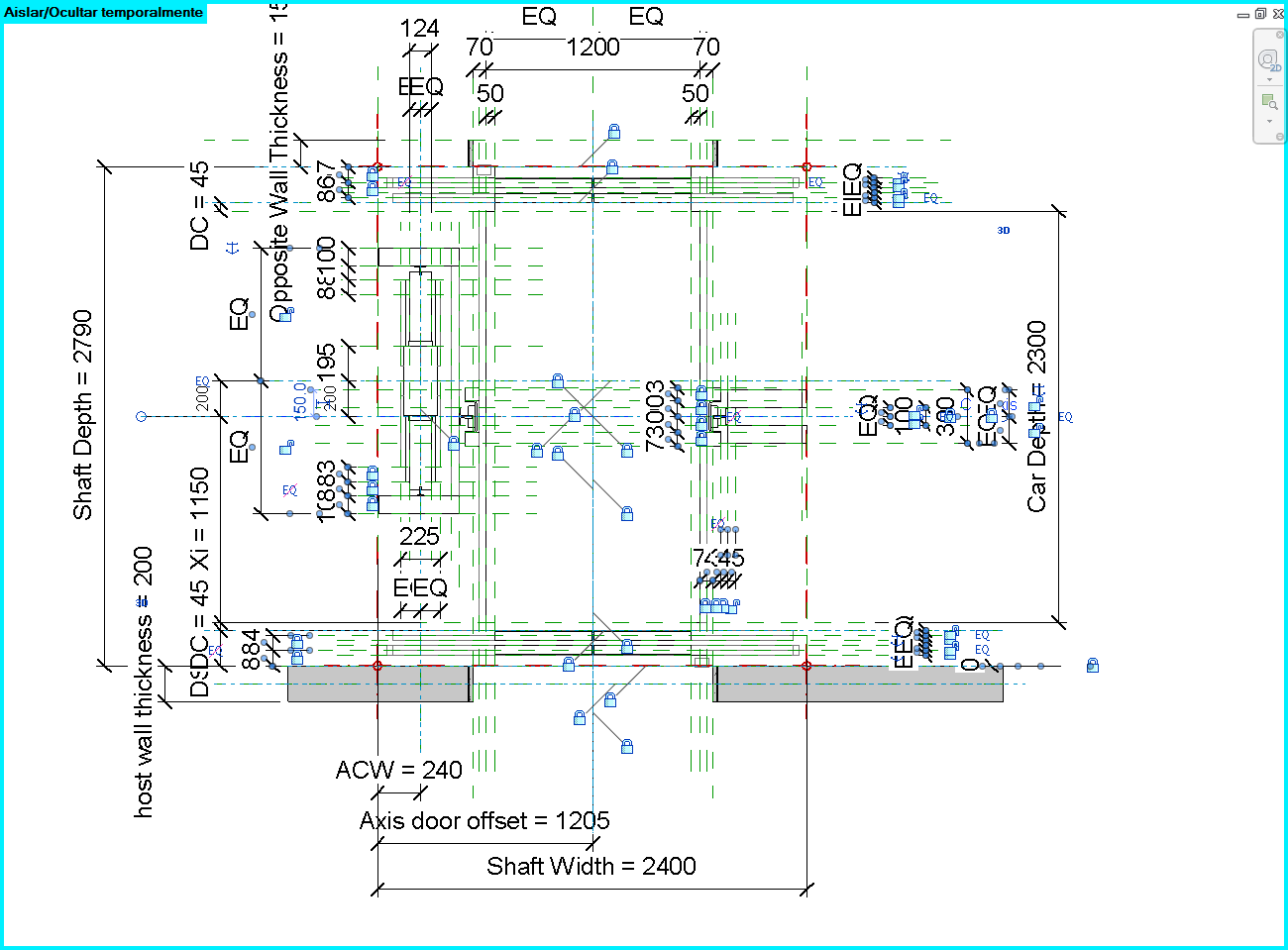
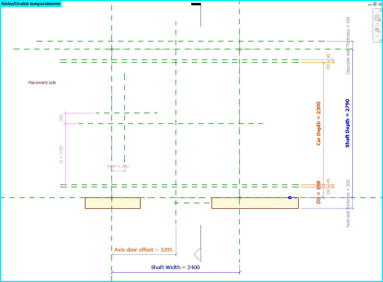
Parametric Skeleton
Parameters are at the heart of a successful Revit Family. While you do not have to make a family parametric, doing so will allow for a single family to be flexible enough to address issues that otherwise may take multiple families to handle. In addition to controlling the dimensions of an object, parameters can control visibility and materials, as well as a host of other types of data, including user-defined text properties for scheduling and annotation.
Reference Planes
Define all Reference Planes needed to define the geometry. Reference Planes provide the skeleton for your family.
The order of creation of the reference planes is crucial. We recommend to categorize them:
- Importants
- Secondaries
- Accessories
Reference planes have a property called “Is Reference”. This property defines the behaviour of the family when loaded into a project and you try to put a dimension or align it. The following options will be available for this property:
- Strong Reference: It sets the highest priority for dimensioning and snapping. When dimensioning or snapping it will be highlighted first.
- Weak Reference: It sets the lowest priority for dimensioning and snapping. When the family is placed into the project and dimensioned, it will be necessary pressing Tab in order to select a weak reference, as any strong references will highlight first.
- Not a Reference: Is not visible in the project environment and cannot be dimensioned or snapped.
Another important property of reference planes in families is the one “Defines Origin”. It will set the location point of the family when placing it in a project. The location point is always define by two reference planes.
In Revit we cannot change the visual style of the reference planes, so we suggest to draw them with different lengths depending on the importance.
Another trick to distinguish the importance of the reference planes is to use dimensions with different styles.
Constrain the Reference Planes
Constrain or assign parameters to the Reference Planes that you have just created. To constraint is the state of being restricted or confined within prescribed bounds.
Be careful and just constrain main dimensions. Do not create reference planes for any geometry you will need and do not constrain every dimension you can, because there probably will be incoherences.
Simply do not overconstrain.

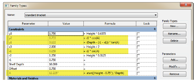
Use formulas to drive parameters
Write down the formulas that define the relation between parameters. These formulas are the key of a parametric Family and some of them will be easy to estimate but others not so much. Define the formulas when creating the parameters of the family types.
You can see the syntax in the following link (very useful post):
http://www.revitforum.org/tutorials-tips-tricks/1046-revit-formulas-everyday-usage.html
Conditional formulas
Conditional statement are really useful when defining formulas for the parameters.
Conditional statement always follow the same structure in Revit:
IF (<condition>, <result-if-true>, <result-if-false>)
Supported Conditional Operators:
< Less than
> Greater than
= Equal
/ Divide
AND Both statements are true
OR One of the statements is true
NOT Statement is false
Conditional statements can contain numeric values, numeric parameter names, and Yes/No parameters, no strings allowed.
Simple IF Statement
IF (Length < 900, <true>, <false>)
Formula That Returns Strings
IF (Length < 900, “Opening too narrow”, “Opening OK”)
Using logical AND
IF ( AND (x = 1 , y = 2), <true>, <false>)
Returns <true> if both x=1 and y=2, else <false>
Using logical OR
IF ( OR ( x = 1 , y = 2 ) , <true>, <false>)
Returns <true> if either x=1 or y=2, else <false>
Nested IF statements
IF ( Length < 500 , 100 , IF ( Length < 750 , 200 , IF ( Length < 1000 , 300 , 400 ) ) )
Returns 100 if Length<500, 200 if Length<750, 300 if Length<1000 and 400 if Length>1000
IF with Yes/No condition
Length > 40
Returns checked box (<true>) if Lenght > 40
NOT with Yes/No condition
not(Viz)
Returns checked box (<true>) if Yes/No parameter "Viz" is unchecked, and returns unchecked box (<false>) if Yes/No parameter "Viz" is checked.
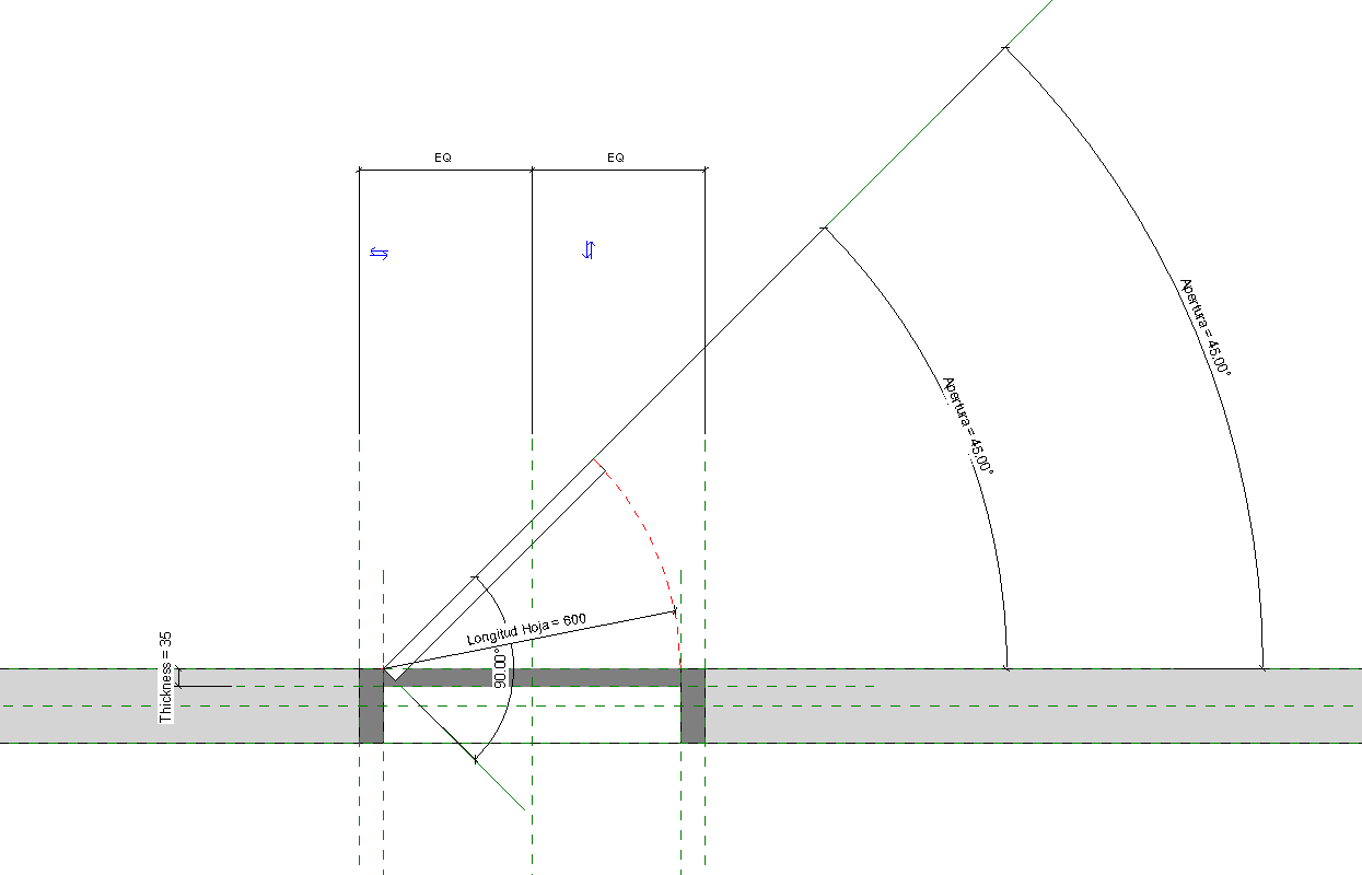
Angular Dimensions
To control the angular dimensions of a family, apply a labelled angular dimension to a reference line.
Unlike reference planes (with infinite extents), a reference line has specific start and end points and can be used to control the angular constraints within components such as a web truss, a door with an instance door swing, or an elbow.
Create Basic Family Types
After the Family Template is chosen, next step proposed is to create two basic family types of the family. As the planning is already done, we know how many types of families we need to do to complete the family. However, in this step we recommend just to do two basic family types. These family types are going to be useful for checking if the family is working appropriately during the process.
Flex the Framework
Once you have laid down your Reference Plane framework and assigned parameters and constraints, test the Family by flexing it. This is done in the Family Types dialog which you can access from the Family Types button on the ribbon. To flex the model, simply try different values for each parameter and then apply. If the framework moves the way you expect, everything is good. Otherwise, undo and try to fix the problem.
It is much easier to fix a problem with conflicting constraints if you know within one or two parameters where the problem may lie. If you wait until you have created and applied four or five parameters before you flex the family and then you have an error, you have a lot more possible conflicts to investigate.
3D Geometry
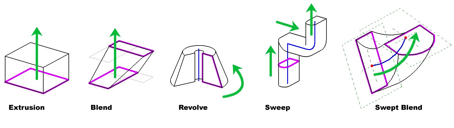
Geometry in Families consists of solid and void forms. Solid forms represent the actual physical parts of the Family and void forms are used to carve away portions of the solid forms.
For instance, you could create a solid form box, and then use a void form to cut a hole in it like a donut. Both solid and void forms come in five varieties. These include: Extrusion, Blend, Revolve, Sweep and Swept Blend. Using a combination of solid and void forms you can create nearly any three-dimensional shape.
Families are either cuttable or non-cuttable. If a family is cuttable, the family displays as cut when the cut plane of a plan view intersects that family in all types of views. If the family is non-cuttable, it displays in projection, regardless of whether it is intersected by the cut plane.
Nested Families
You can build complex forms using a combination of the solid and void forms available in the Family Editor as noted above. In some cases however, managing a complex form in a single Family can become cumbersome. In some cases, it makes sense to break your object into discrete parts and build the parts as separate Families. You can then insert these simpler Families into another Family that represents the whole (host family). This is referred to as nested Families. When you manage your complex Families in this way, you gain more control and flexibility.
Moreover, nesting helps with rotation, mirroring and arrays. If you need to rotate, move or mirror an element parametrically or wish to make a parametric array in your family, nesting is almost a must. It is possible to achieve these behaviours without nesting, but it can be much more challenging.
Give careful consideration to how many levels of nesting you introduce in the model. It is possible to nest multiple layers deep. In other words, you can nest family A into family B and then in turn nest family B into family C and so on. There can be benefits to doing this, but each level of nesting you introduce will increase the complexity of the final family, and will make it more challenging to track down problems when it does not flex properly, as well as increase the size of the family and therefore the size of the final model.
Associate Parameters
By associating family parameters, you can control the parameters of families nested inside host families from within a project view. You can control instance parameters or type parameters.
To associate parameters, they must be the same type. For example, associate a text parameter in the host family with a text parameter in the nested family.
You can associate a host-family parameter with more than one nested family parameter of the same type. Also, you can associate this parameter with multiple nested families.
Shared Parameters
Shared parameters are parameter definitions that can be used in multiple families or projects.
Shared parameter definitions are stored in a file independent of any family file or Revit project; this allows you to access the file from different families or projects. In order for information in a parameter to be used in a tag, it must be a shared parameter. Shared parameters are also useful when you want to create a schedule that displays various family categories; without a shared parameter, you cannot do this. If you create a shared parameter and add it to the desired family categories, you can then create a schedule with these categories. This is called creating a multi-category schedule in Revit.
You can find the Shared Parameters command on the Manage tab on the ribbon. There are two basic procedures to follow. You can create a new Shared Parameter file or you can browse to and open an existing one (In most cases, you will want to have only one Shared Parameter file for the entire office). Shared Parameters files are organized into groups. Groups can be named anything you like and are used simply to organize the file.
Shared Families
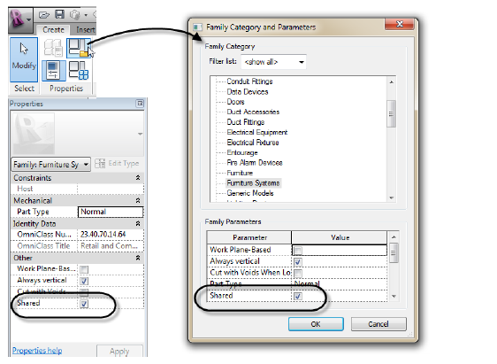
Let's join the previous two topics together. If you have created Shared Parameters to report in your schedules and tags and you are using nested families, then it is important that you also consider using Shared Families. A Shared Family enables the nested family to appear as a separate selectable element in the host family or project. If you have parameters in the nested family that you wish to tag or schedule, you must use a Shared Family. You can do this with the “Family Category and Parameters” dialog or directly on the Properties palette.
Whether you share families before you nest them determines the behavior of the nested geometry in elements that you create with the family.
- If you nest a family that is not shared, components created by the nested family act with the rest of the element as a single unit. You cannot select (edit), tag, or schedule the components separately.
- If you nest a shared family, you can select, tag, and schedule the components separately.
Source: autodesk
There is a very important consideration when using Shared Families. If you have nested families that rely on linked type parameters, you cannot make the family shared. Shared Families cannot have their type parameters driven by a host family. So you either have to avoid nesting, use instance parameters or not use Shared Families.
Report with Nested Generic Annotation Families
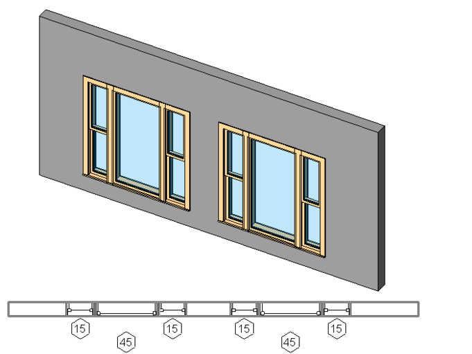
You can nest generic annotation families inside host model families, so that the annotations appear in the model. This is useful if you want to include a label with a model family and display that label in the project.
Generic annotations hosted into model families have an absolute print scale when they are loaded into the project. This means that when you place the family with the nested generic annotation, the last will display at the same size, regardless of view scale. You can also control the visibility of generic annotations in the project separately from the host model family.
In order for information in a parameter to be used in a tag, it must be a shared parameter.
Nested Family with Interchangeable Components
You can create families that feature interchangeable nested components when added to your models.
To control the type of family within a nested family, you create a family type parameter that can be either an instance or type parameter. After you label a nested component as a family type parameter, subsequently loaded families of the same type automatically become interchangeable without any further work.
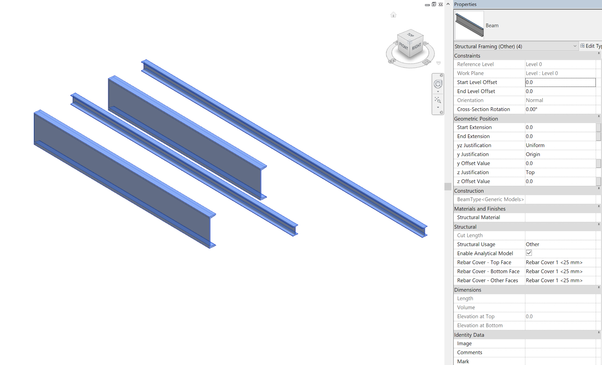
Using Family Type Parameters in Formulas
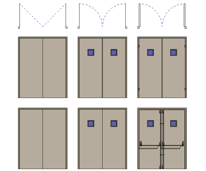
You can use family type parameters in formulas to, say, change the shape of a beam when the length goes above a certain value. In the picture below, the 4 beams belong to the same family but the longer ones have a double T-shaped profile and the shorter ones have a C-shaped profile.
To achieve this behavior, create a beam using the Structural Framing template. Save it as Beam.rfa.
Then create two generic model, line based families with a sweep, one using a double T shaped profile (Beam T.rfa) and another using a C-shaped profile (Beam C.rfa)
Load both families in Beam.rfa. Place one instance of the Generic Model, line based family and constraint it to the driving reference planes.
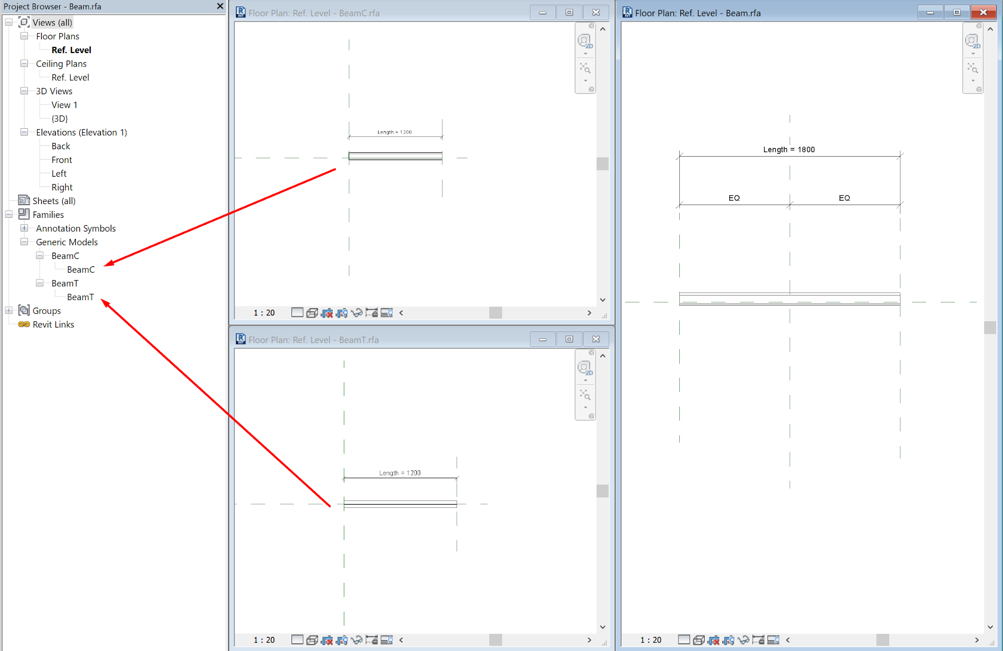
Now create three family type parameters. One (BeamType, instance) to drive the shape of the Generic Model instance by assigning the label.
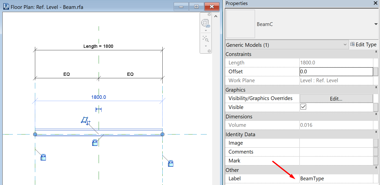
Two to hold the types for both options (BeamTypeA, BeamTypeB, type) and assign the formula as shown.
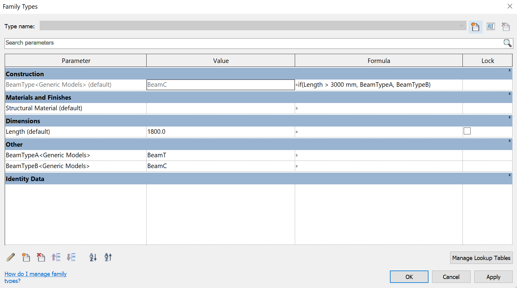
Bottom Line
You cannot assign family type parameter to profiles directly. You must use a workaround creating generic model, line based families.
You cannot write types directly into formulas, but you can create holding parameters to store the types of interest and reference them in your formulas.
2D Drawings
Detail Levels and Display in Views
Visibility of a family determines in which view the family displays and what it looks like in that view. Typically, when an element is created by a family, the geometry of the element will change, depending on the current view. In a plan view, you may want to see a 2D representation of the element. In a 3D or elevation view, you may want a fully detailed 3D representation of the element. You have the flexibility to display different levels of geometry.
The visibility settings of each element in your Family can be customized to determine when they display. Conditions available include Plan/RCP, elevation views and Coarse, Medium and Fine detail levels. So. you can adjust the level of detail of each view (9 combinations).
Complete the Parameterization
Check that your Family has all the parameters you need to define it: sizes, materials, information elements, etc.
In addition to deciding what the parameters need to be, you will also need to consider whether they will need to be used in schedules or tags, and whether they will be type or instance parameters.
When creating a parameter, there are several items that you need to consider carefully:
Will the parameter need to be reported in a schedule or will it need to be part of an intelligent annotation tag? If so, it will need to be a shared parameter. Shared parameters are stored in an external text file so that they can be accessible to multiple projects.
What type of parameter is it? Length parameters are applied to dimensions. Material parameters can control the material assigned to a piece of model geometry. Yes/No parameters will provide a checkbox type of parameter. The parameter type is crucial to the behaviour of the parameter.
The parameter discipline will control what types of units are available for the parameter.
Will the parameter be type-based or instance-based?
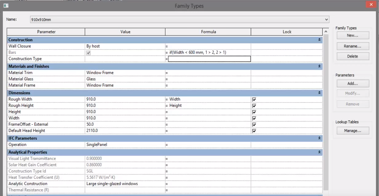
Visibility Parameters
Revit has the ability to use if statements and (Yes/No) parameters to control the visualization of elements within families. For instance, we can turn off some elements when the width of the family is smaller than a specified size.
When selecting the elements we have to click on the Graphics/Visible of the Properties window and Associate a Parameter.
The visibility parameters only work once the family has been either loaded into another family or loaded into a project. Once the visibility parameter has been added to the family, we can use an “if” statement to set the options based on a condition.
If (condition, true, false)
Complete all the Family Types
Complete all the Family Types that you need. Complete all the types changing the value and information of the parameters created.
If you want to control the values of the family types parameters carefully, you can simplify the process using Excel.
A type catalog lists all of the types in a family, allowing you to select and load only the types you need for the current project, resulting in a smaller project file size.
To create a type catalog, you create an external text file (TXT) that contains the parameters and parameter values that create the different types in a specific family. You place this file in the same location as the family file so that when you select to load the family, the type catalog displays.
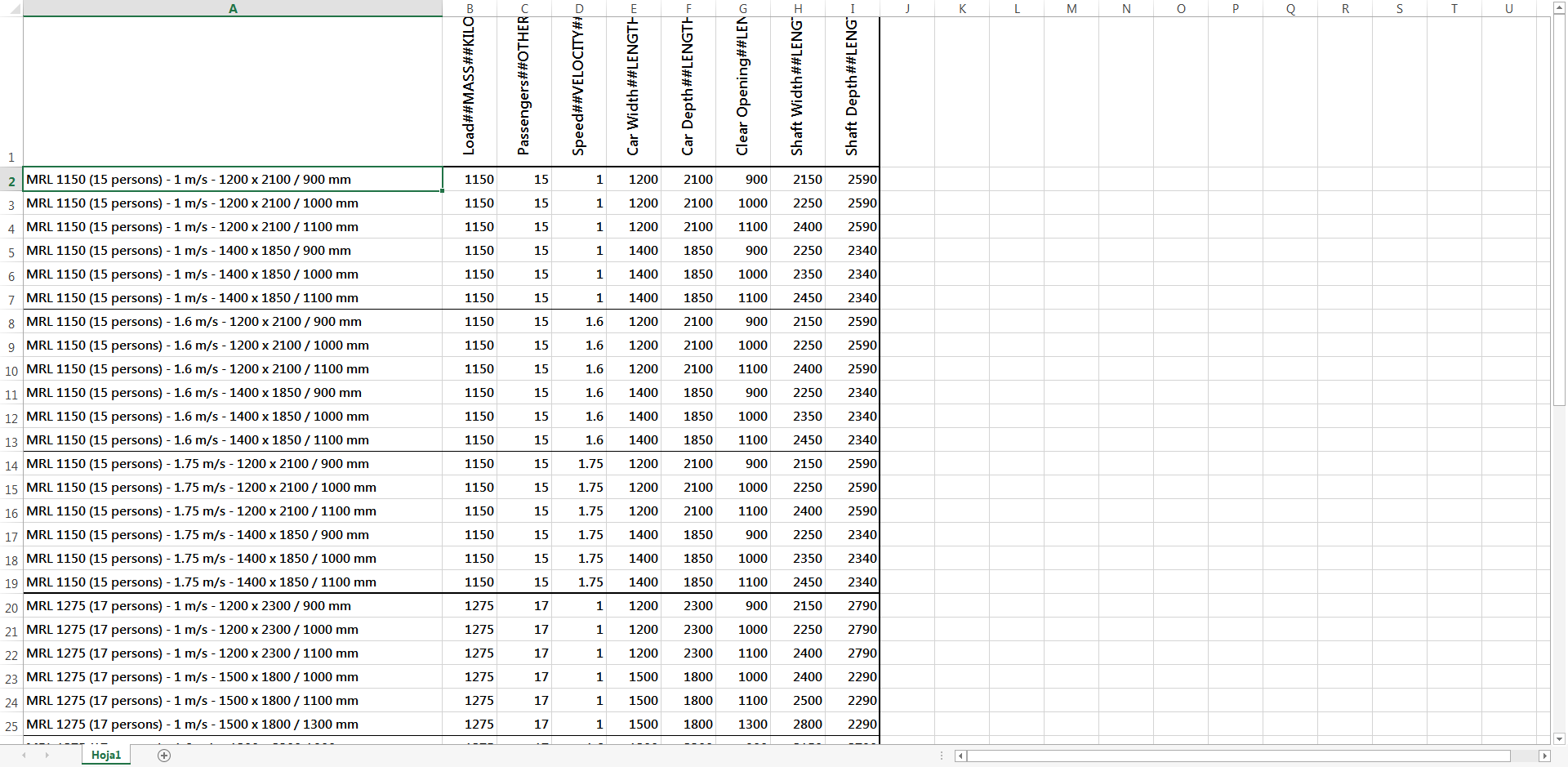
The easiest way to create a type catalog is to use the Export Family Types tool on an existing family. Using this tool, you create the base type catalog and then modify the text file in a text editor.
The original document exported, may seem a mess but after changing some aspects in Excel we can read it properly and afterwards modify it.
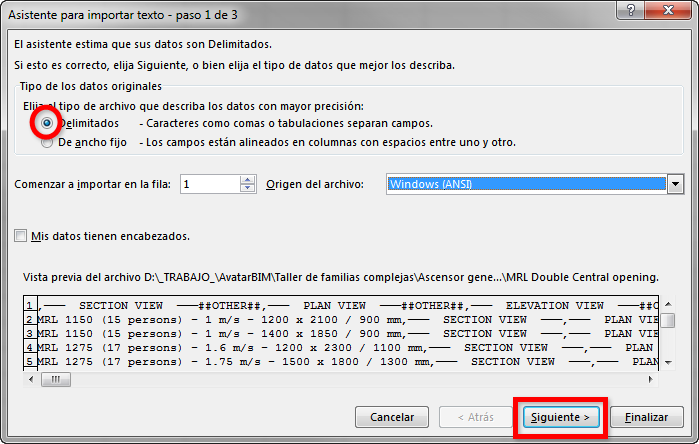
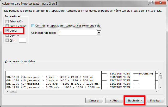
You can define additional parameters as needed, making sure to use the delimiter and syntax specified in Revit. Then, you have to place the file in the same location as the family file so that when you select to load the family, the type catalog displays.
Be careful when saving the file, select .csv type but name with .txt extension.
Tips & Tricks
- Automatic Sketch Dimensions: Automatic sketch dimensions are turned off by default. Revit LT now knows where each line of this geometry exists with respect to reference planes or other sketch lines. If we turn on the automatic sketch dimensions, Revit will show all these dimensions. As you add locked dimensions, they replace the automatic sketch dimensions, as shown. They only display if there is at least one labeled dimension in the family.
- Create your formulas in Notepad++, specially if they contains nested IF statements. Revit formulas editor simply sucks: https://notepad-plus-plus.org/download/v7.5.1.html
- Angular dimensions usually crash when you work with pure angle values like 0º or 90º. You can use constrained revolves in order to get a better performance of your angle based objects.
- The best way to flex your family is to load it into the project.
Conclusion
In this guideline we have covered all the process of creating a family pointing out most advanced settings and possibilities that the families offer.
- Reference Planes (categorization).
- Angular Dimensions.
- Nested Families.
- Shared Parameters and Shared Families.
- If statements and Yes/No visibility parameters.
- Type Catalog.
- Automatic Sketch Dimensions.
hola quisiera saber si dan cursos de familias avanzadas, gracias.
Hola Javier,
Disculpa la tardanza en contestar.
Actualmente no damos cursos a particulares, solo a empresas. No obstante, te recomiendo estar atento para el próximo Algomad. En ese evento suele haber workshops y conferencias muy interesantes sobre BIM, automatizaciones y nuevas tecnologías en el mundo de la construcción. Si nos sigues en LinkedIn podrás enterarte de cuándo será el próximo!
Un saludo.
Hola Darlin Javier, ahora puedes hacer el curso de familias avanzadas de Modelical Campus, está incluido en la suscripción.
https://www.modelical.com/es/campus/catalogo/revit-architecture-familias/
Espero que te resulte interesante.
Hi,
I have a question about Nested switching family, I’m not sure if it is possible to do, because I have searched throughtout the internet I haven’t found any similiar situation with I’m looking for
How can I set up a family type to switch its type itself in case it measure get changed in the project?
For example if there is one steel beam connecting two columns. Let’s regard that the distance between two columns is 3000 mm and for this far distances I have to use BEAM A. So I realised that the dsitance between the columsn have to be 5000 mm instead. But for that far distance I need to use BEAM B that is stronger than BEAM A. Both of BEAMS are a family nested with different types. So How could I create a parameter to limited and change the beams according to the distance typed in the the project?
I’ve tried to use the syntax according to each beam lenght, but the software doesn’t allowed me to create a syntax with the Length parameter which is from the structural framing template family.
I look forward to hering from you which follow should I fallow.
Cheers.
Hello Tito, thanks for your comment, we have updated our guideline to answer your specific question. Have a look at
https://www.modelical.com/en/gdocs/complex-families/#h.rfhkes1q5uxn
Hope this helps.
Hi Roberto,
Thank you for the tips, I just didn’t understand why I still able to see three beams, even though I createded a formula as you suggested.
Thanks.
Hola, tengo una duda acerca de las familias. Si yo quisiera introducirle 50 parámetros compartidos, ¿como hago para agilizar? Puesto que tengo que ir uno por uno y es súper tedioso.
Estoy creándome mis propias plantillas con dichos parámetros ya preestablecidos, pero cuando lo que quiero es meter datos a familias ya existentes me vuelvo loca.
A ver si podéis orientarme, muchas gracias de antemano. Saludos
Hola Rocio. Es posible hacerlo con la API de Revit, por lo que normalmente se desarrollan addins o piezas de código para hacer esto. En Modelical lo hacemos con Family Matters te dejo algún ejemplo de personas que han compartido sus soluciones. Ejemplo 1. Ejemplo 2. Ejemplo 3.
Un saludo