
Electrical Modelling
Operation in Revit
Electrical Modelling
Objectives
- General knowledge of how the electrical installation of a building works.
- Knowing the general configuration of electrical systems.
- Classify each element of the electrical system in Revit.
- Understanding circuits and connectors.
Prerequisites
- The user will be using Revit 2018 or later.
- The user should be familiar with real electrical solutions.
Introduction
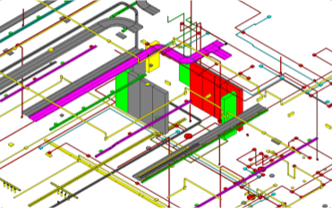
Electrical modelling is one of the most unknown subjects when working with Revit. This document is a complete guide on the main aspects that have to do with electricity in this program, from the basic knowledge of an installation, to the configuration, modelling and documentation of the different elements that make it up.
Index
This guide consists of the following sections:
- Basic notions of the electrical systems of a building: Brief description of how a building’s electricity system and its components work.
- General configuration of the model: Knowing how a model should be configured before starting the electrical modelling.
- Electrical families: classification in relation to the elements of a real electrical installation. It is not explored in this guide, for further details, please consult the Electrical Families Guide.
- Modelling of the electrical system: Methodology for modelling trays, tubes, switch systems and electrical circuits.
- Documentation: How to manage and document electrical system information.
1. Basic notions of electrical systems in a building
Types of electrical current
Direct current (DC)
This is the type of current generated by generators such as batteries and dynamos. This current does not vary over time in value or direction, and always moves from the positive to the negative pole of a generator.
Alternating current (AC)
This is the current that is generated in power stations, and reaches our homes through electrical installations. In contrast to direct current, it changes in intensity and direction over time. All power grids use this type of electrical current for various reasons:
- Generators are cheaper, and need less maintenance.
- Transport is more efficient; this type of current can be transformed into high or low voltage.
- Most motors run on alternating current, which makes them more efficient and simpler than direct current motors.
Types of alternating current:
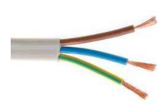
- Single-phase current: the most common, there is a single current signal that is transmitted through the phase cable and returns through the neutral cable that closes the circuit. The single-phase system uses a voltage of 230V between phase and neutral.
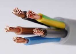
- Three-phase current: Allows the operation of three-phase electric motors and the use of a smaller cable section. It is a system of three coupled alternating currents, each one is carried by a phase conductor and the return is common with a neutral conductor, which closes the three circuits. The three-phase system uses a voltage of 230V between phase and neutral, and 400V between phases.
Structure of the electrical installation
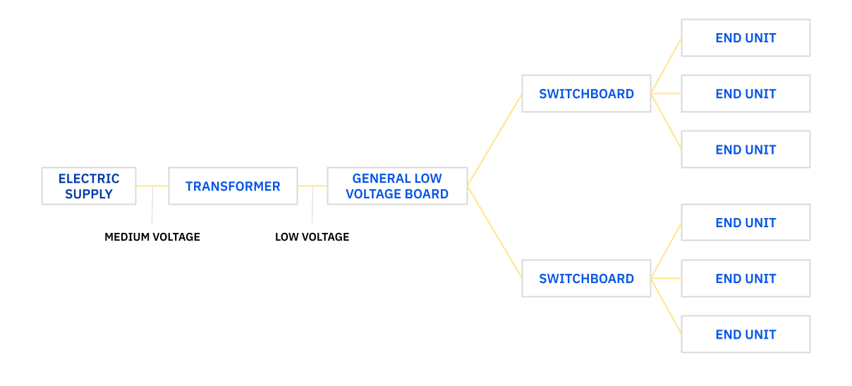
The starting point of the installation is the connection to the network on the public road, that is, to the supply from the electricity company. In the transformer, the energy is transformed from medium to low voltage, and from the general low voltage switchboard it is distributed to the different distribution switchboards in the building, which will finally serve the terminal elements.
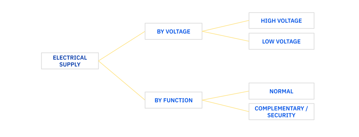
Classification of electrical installations
The electrical installation of a building is classified according to its function and voltage.
Elements and components
Supply Connection
This is the electrical connection point on a public road, where the utility company (power company) provides electrical service to the building.
It is usually located on the outside of the building. It can be overhead (on the façade), underground or mixed, and the distribution company is responsible for it.
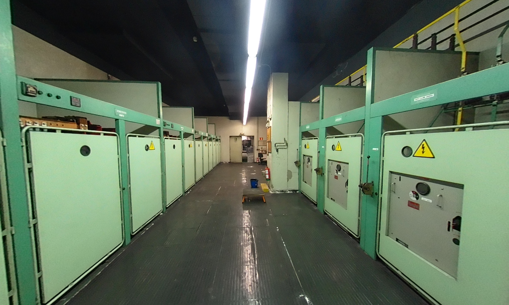
Electrical Substation
Substations fed by a High or Medium Voltage network in which the voltage reduction takes place and so Low Voltage lines originate. Inside buildings they are usually located in the basement: in rooms with high protection, with restricted access, due to the risk of the installation.
Electrical substations are mainly composed of the transformer, cubicles and protection relays.
These elements are modelled as electrical equipment as volumetric representations.
General Low Voltage Switchboard
This element distributes and protects the low-voltage electrical energy in a certain number of outlets, depending on the supply (general lighting, emergency lighting, general power, etc.), to the distribution panels distributed throughout the building.
The switchboards are modelled as electrical equipment as volumetric representations.
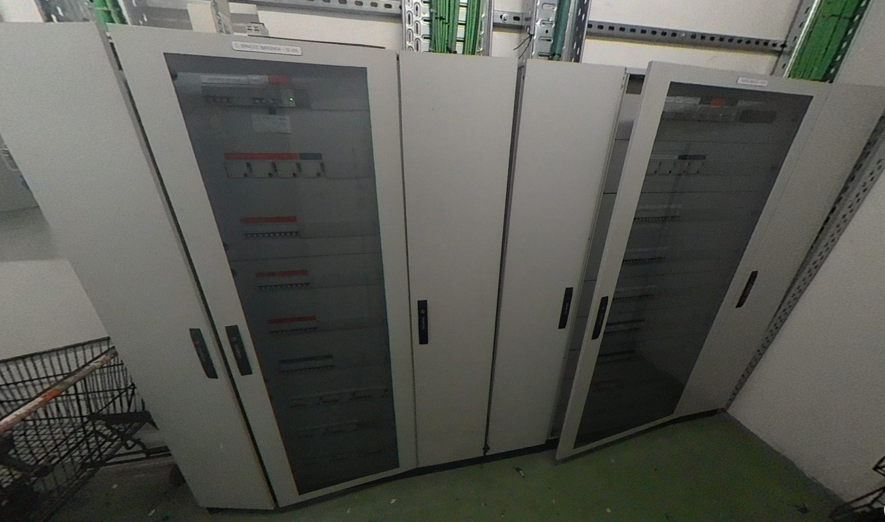
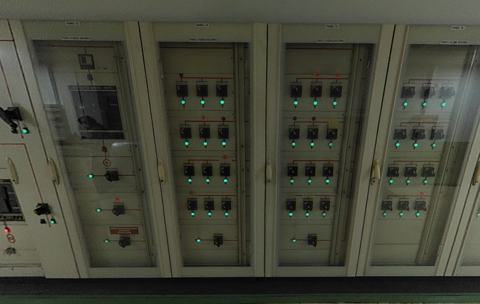
Distribution boards
Distribution switchboards are secondary or partial switchboards, whose power supply comes from the general low-voltage switchboard. They ultimately distribute the power supply to the receivers in different areas or parts of the building, depending on their supply.
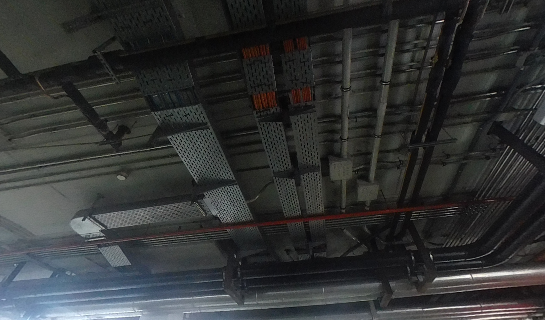
Wiring conduits/trays
Trays, conduits and ducts through which the wiring that distributes the electrical supply runs.
Wiring cannot be modelled in a Revit model, only a 2D representation could be created when the elements are circuitted.
If necessary according to project requirements, we could model the wiring by creating a special type of tube which we would call 'Cable'.
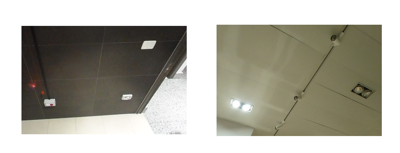
End units
These are the final elements and mechanisms of the electrical installation, such as sockets, light fixtures, switches, machine connections... These elements are modelled as Electrical Fixtures and Lighting Fixtures, with as much detail as the project requires.
2. General settings
Before loading, modelling and connecting electrical elements, we must review the electrical settings of the project.
We can run different calculations in Revit with our electrical systems, but we must configure them properly to obtain valuable results. Some of these calculations are:
- Real loads per room
- Number of elements connected to a circuit
- Cable sizes
- Cable lengths
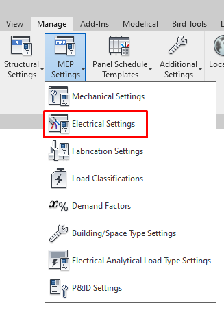
To access the electrical settings, go to Manage → MEP Configuration → Electrical Configuration, or use the keyboard shortcut "ES".

Hidden Line
The first configuration section when opening the Electrical Settings is Hidden Line, through which we can specify how hidden lines are represented.
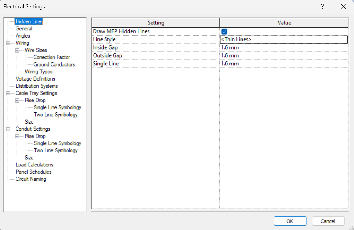
We find the following parameters:
- Draw MEP Hidden Lines: we choose whether the intersection in plan of a cable tray and pipe is represented as specified in the parameters. For this configuration to apply, we must have the view in either the Electrical, Mechanical or Plumbing disciplines.
- Line Style: Line style to represent the hidden segment at the plan intersection of the cable tray or pipe.
- Inside/Outside Gap: gap of the lines external to the plan intersection of the cable tray or pipe.
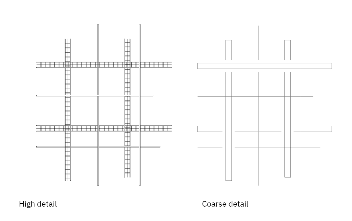
- Single Line: separation of the single hidden lines at the point of intersection of the cable trays or pipes in plan. Trays are represented as a single line only in the coarse detail model, while pipes are represented as a line in medium and coarse detail.
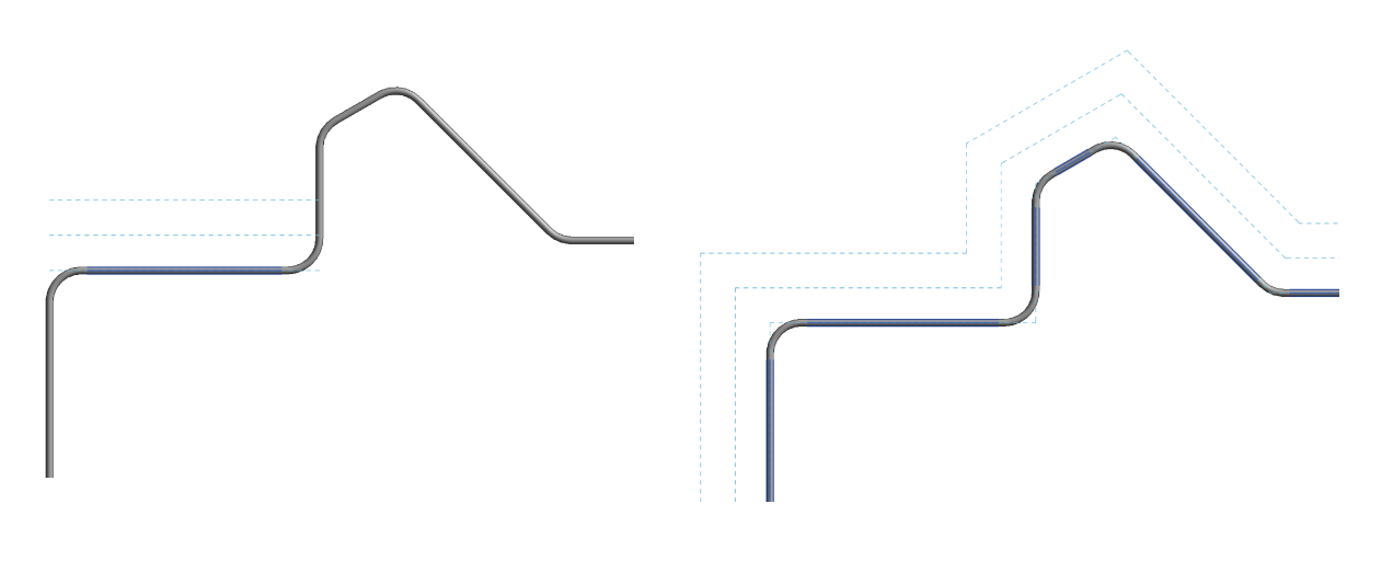
This is a graphical setting. It is useful to represent the crossings of cable trays and pipes at different heights in plan, when using a coarse or medium detail, when the pipes or cable trays are represented as a line. However, if we use a high detail view, we must deactivate 'Draw MEP Hidden Lines', as the crossings are represented clearly:
General
The next section is the GENERAL section. Here we can configure how certain information will appear for electrical systems by default.
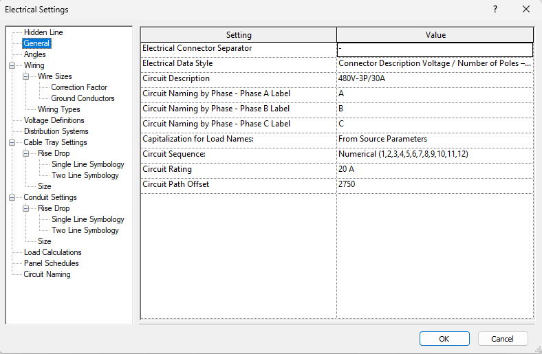
We find the following parameters:
- Electrical Connector Separator: it is the symbol we choose to separate the values of the "Electrical Data" parameter of devices.
- Electrical Data Style: we can choose the style of the parameter group "Electrical Data" out of the properties of electrical components, which can be:
- Connector Description Voltage / Number of Poles – Load
- Connector Description Voltage / Phase – Load
- Voltage / Number of Poles – Load
- Voltage / Phase – Load
- Circuit Description: specifies the format of the parameter “Circuit Description” in the wiring properties.
- Circuit Naming by Phase - Phase Label (A,B or C): Values that are used if specified for the group via the "Properties" palette, according to the project nomenclature. A, B and C are the default values.
- Capitalization for Load Names: specifies the format of the parameter “Load Name” in the circuit settings.
- Circuit Sequence: points out the sequence in which circuits are created and allows to create circuits grouped by phase.
- Circuit Rating: default rating when a circuit is created.
- Circuit Path Offset: the default offset when a circuit path is generated.
Angles
The following section is ANGLES. Here we can configure the angles that Revit will create when modelling joints between elements.
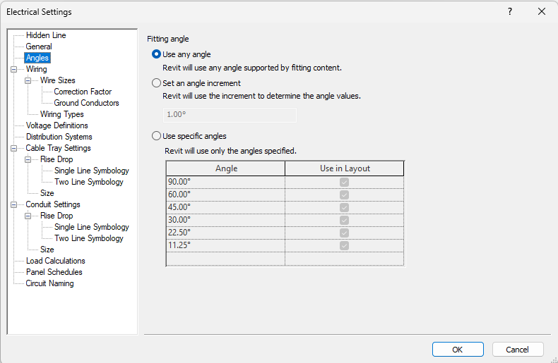
We find the following parameters:
- Use any angle: with this option there is no angle restriction when modelling joints. This option is recommended for better versatility.
- Set an angle increment: here we can set the angle increment to be used to determine the angle values.
- Use specific angles: specific joint angles can be defined. With this option the modelling will be restricted to specific angles.
It is recommended to use "Use any angle" instead of "Use specific angles", as the latter option would restrict the modelling to the specified angles, with the subsequent loss of versatility.
Through the option "Set an angle increment" we can set the angle increment to be used to determine angle values.
Wiring
The following section is WIRING. Here we can determine how Revit sets cable sizes, and how these will be represented in plans.
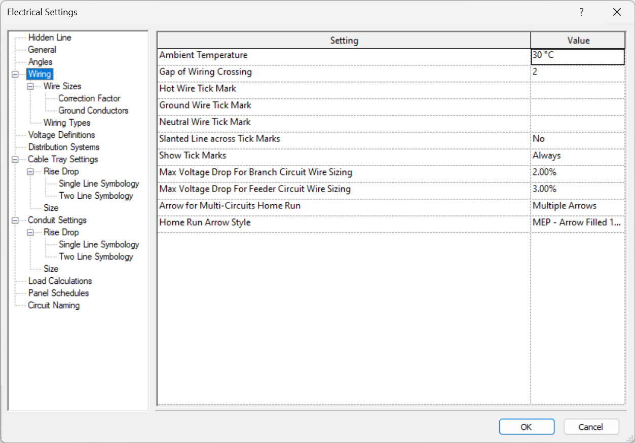
Settings are based on the following parameters:
- Ambient temperature: changing the temperature directly affects the correction factors in cable sizing.
- Gap of Wiring Crossing: this is like the "hidden line" for cables (it is measured in mm in paper space, so if we change the scale of our view this gap will be affected).
- Wire Tick Marks (Hot, ground and neutral): here we can specify the style of marking shown. We can load an annotation family, although Revit provides four marking styles:
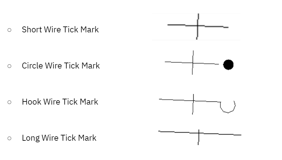
- Slanted Line across Tick Marks: Specifies whether to display the tick mark for the ground conductor as a diagonal line that crosses the tick marks for the other conductors.
- Show Tick Marks: here we can choose to show tick marks always, never, at home runs or at end wire home runs.
- Max Voltage Drop For Branch Circuit Wire Sizing: specifies the percentage for the maximum voltage drop allowed for branch circuits.
- Max Voltage Drop For Feeder Circuit Wire Sizing: specifies the percentage for the maximum voltage drop allowed for feeder circuits.
- Arrow for Multi-Circuits Home Run: specifies whether a single arrow or multiple arrows display on all circuit wires or the end wire only.
- Home Run Arrow Style: specifies the style for the home run arrow, including the arrow angle and size.
Wire Sizes
The wire sizes panel provides information for the Wire Types available with Revit. Here, we can manage and define the wire sizes we will be able to use in Revit.
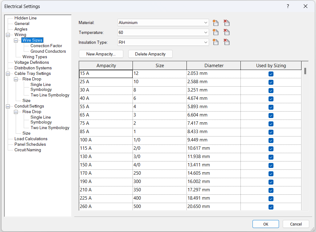

Each size shows:
- Ampacity: maximum ampacity supported by the wire size.
- Size: tamaño de AWG (American Wire Gauge), is the integer number that corresponds to a specific dimension for the wire diameter.
- Diameter: dimension of the wire.
- Used by Sizing: if we activate this, the wire will be available for its use in circuits in which Revit calculates the wire size.
Revit calculates the diameter of the wires (based on the current ratio of the circuit) to maintain a voltage drop of less than 3%.
Correction factor
Here we can define the temperature and correction factor for cable calculation. We can add or delete as many as we need.
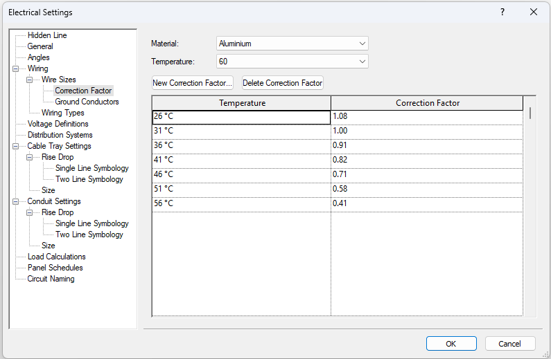
We find the following parameters:
- Temperature: defines the ambient temperature, this affects the current carrying capacity of the cable.
- Correction Factor: this is the factor used to calculate the cable size of the project, depending on the temperature.
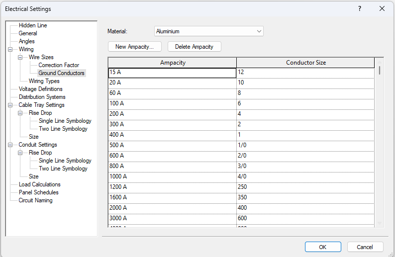
Ground conductors
Lists the ampacity of wiring used to select the size of ground conductors for Revit.
Wiring Types
In Wiring we also find the Wiring Types subgroup, in which we can define the wiring characteristics.
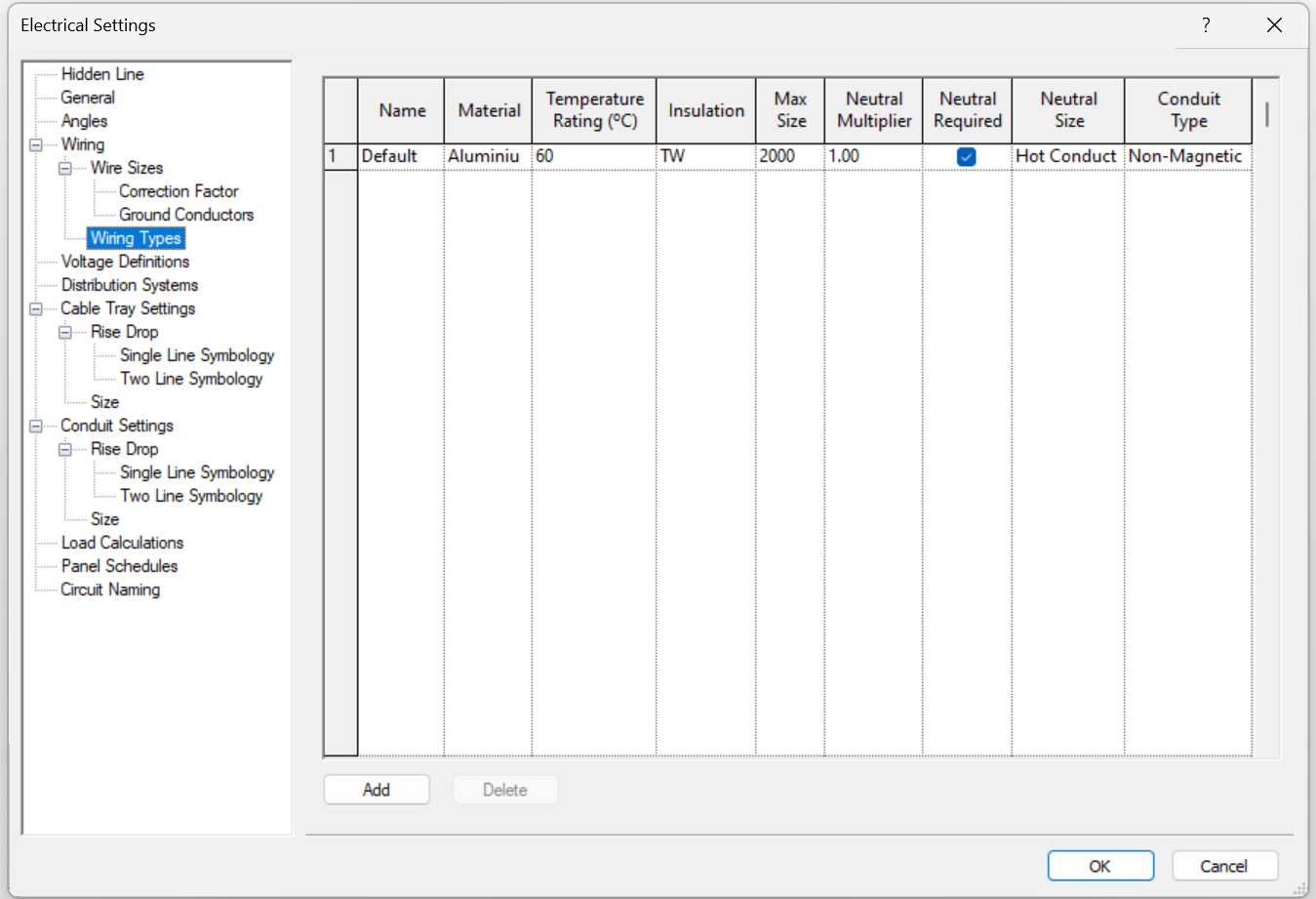
The fields in the Wiring Types table are as follows:
- Name: this is a user-defined string that identifies a particular wire type
- Material: Copper, Aluminum, or another project specific material previously defined in the New Material dialog.
- Temperature Rating: same as the material, if we want to assign other temperatures, they must be previously created in Wire Sizes.
- Insulation: several insulation types can be specified, including a project specific insulation as defined in the New Insulation dialog.
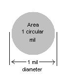
- Maximum size: maximum conductor size to be used when sizing wires of this type from 14 to 2000 MCM (thousand circular mils). This parameter lets you control when wires start being sized in parallel runs rather than by simply increasing the wire size until 2000 MCM is reached. Remember: 1cm = 5.067x10⁻⁴ mm².
- Neutral Multiplier: the specified value is used to increase or decrease the calculated size of the neutral conductor, based on a multiplier of the conductor’s size. It is applied after the neutral conductor is calculated, either by sizing it the same as the hot conductors or according to unbalanced current.
- Neutral Required: if not selected, a neutral will be omitted for balanced loads, and will be included for unbalanced loads.
- Neutral Size: the baseline for the size of the neutral will be the same as the hot conductor, except for calculations with unbalanced current, in which the neutral will be sized based on the amount of current flowing.
- Conduit Type: the material of the conduit directly affects the wire impedance calculations.
Voltage Definitions
Here we can define voltage ranges.
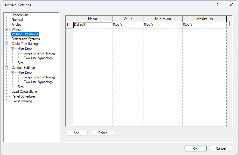
We have to define the voltage ranges before setting up Distribution Systems, as Voltage Definitions are different in almost all countries.
We find the following parameters:
- Name: identifies a voltage definition.
- Value: defines the actual voltage for the voltage definition.
- Minimum: lowest voltage rating for electrical devices and equipment.
- Maximum: highest voltage rating for electrical devices and equipment.
Distribution Systems
Here we can define the distribution systems that will be available and that we will be able to associate to electrical panels. The system distribution table is where we define the systems that are available for the project.
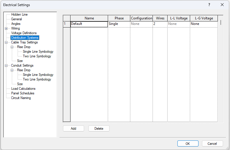
We find the following parameters:
- Name: defines the unique name that identifies a distribution system.
- Phase: we can choose between Three or Single, depending on the instalación.
- Configuration: available for three-phase systems only, allows us to select between Wye or Delta (increment).
- Wires: specifies the number of conductors; 3 or 4 for three-phase, 2 or 3 for single-phase.
- L-L Voltage: not applicable for a single-phase, 2-wire system. We can select a Voltage Definition that represents the voltage measured between any two phases. This parameter depends on the Phase and Wire selections.
- L-G Voltage: always available, select a Voltage Definition that represents the voltage measured between a phase and ground.
Cable Tray Settings
The following segment is the CABLE TRAY SETTINGS.
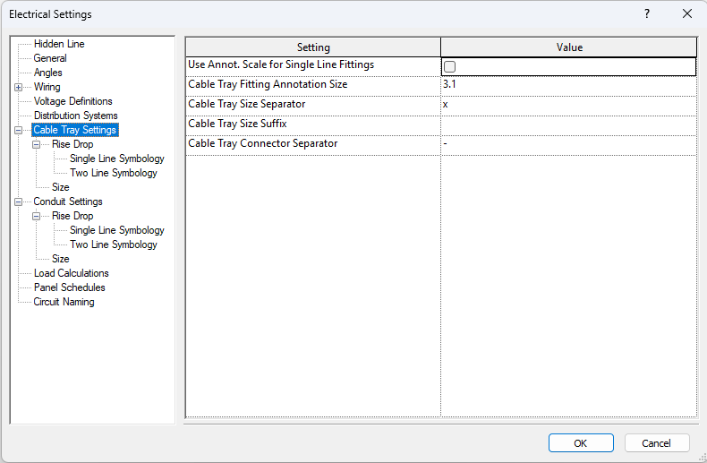
We find the following parameters:
- Use Annot. Scale for Single Line Fittings: specifies whether cable tray fittings are drawn at the size specified by the Cable Tray Fitting Annotation Size parameter.
- Cable Tray Fitting Annotation Size: specifies the plotted size of fittings drawn in single-line views, regardless of the drawing scale.
- Cable Tray Size Separator: specifies the symbol to be used in showing cable tray sizes. For example, when an x is used, a cable tray that is 30cm high and 5cm deep would be shown as “30x5”.
- Cable Tray Size Suffix: symbol appended to the cable tray size.
- Cable Tray Connector Separator: symbol used to separate information between two different connectors.
Rise Drop (Cable Tray)
In the subgroup Rise Drop we can configure the visualisation settings of cable tray annotations and symbols.
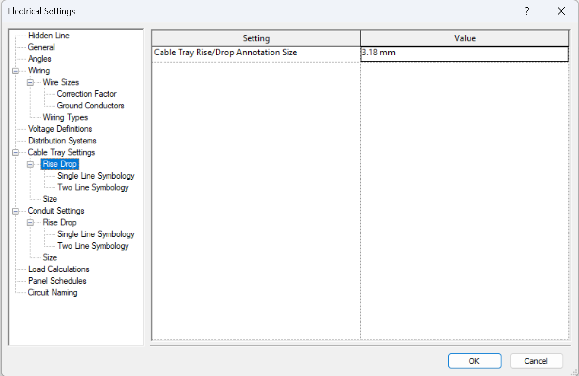
We find the following parameters:
- Cable Tray Rise/Drop Annotation Size: specifies the plotted size of rise/drop symbols drawn in single-line views, regardless of the drawing scale.
- Single Line Symbology: specifies the rise symbol and drop symbol used in single-line views.
- Two Line Symbology: specifies the rise symbol and drop symbol used in two-line views.
Size (Cable Tray)
The following subgroup is Size:
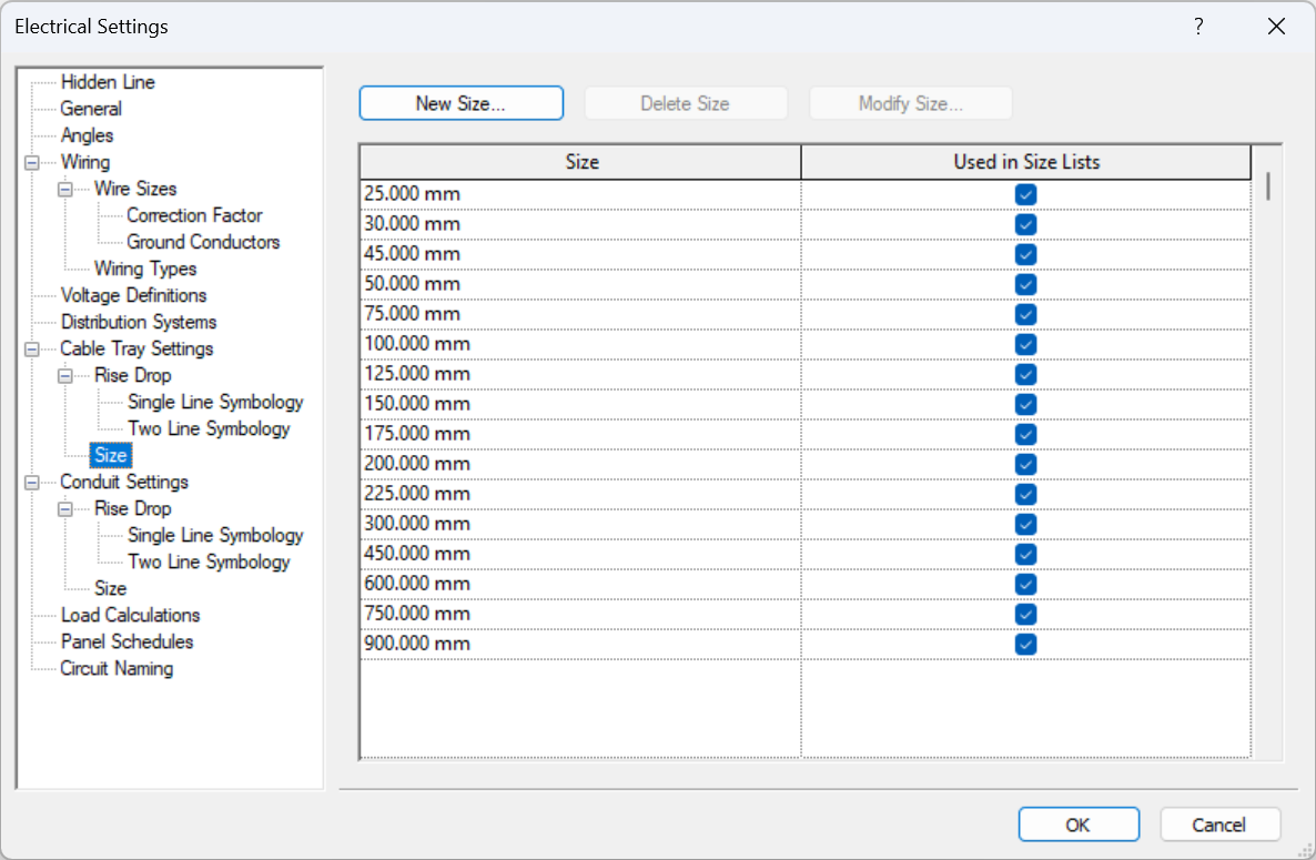
In the cable tray size subgroup we can add, modify or delete sizes as needed.
Conduit Settings
The following subgroup is Conduit Settings:
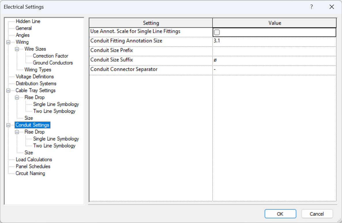
We find the following parameters:
- Use Annot. Scale for Single Line Fittings: Specifies whether conduit fittings are drawn at the size specified by the Conduit Fitting Annotation Size parameter.
- Conduit Fitting Annotation Size: plotted size of fittings drawn in single-line views, independent of the drawing scale.
- Conduit Size Prefix: specifies the symbol preceding the conduit size.
- Conduit Size Suffix: specifies the symbol appended to the conduit size.
- Conduit Connector Separator: symbol used to separate information between two different connectors.
In the conduit settings we will find the same subgroups as found on cable tray settings.
Rise Drop (Conduit)
In the subgroup Rise Drop we can configure the visualisation settings of conduit annotations and symbols.
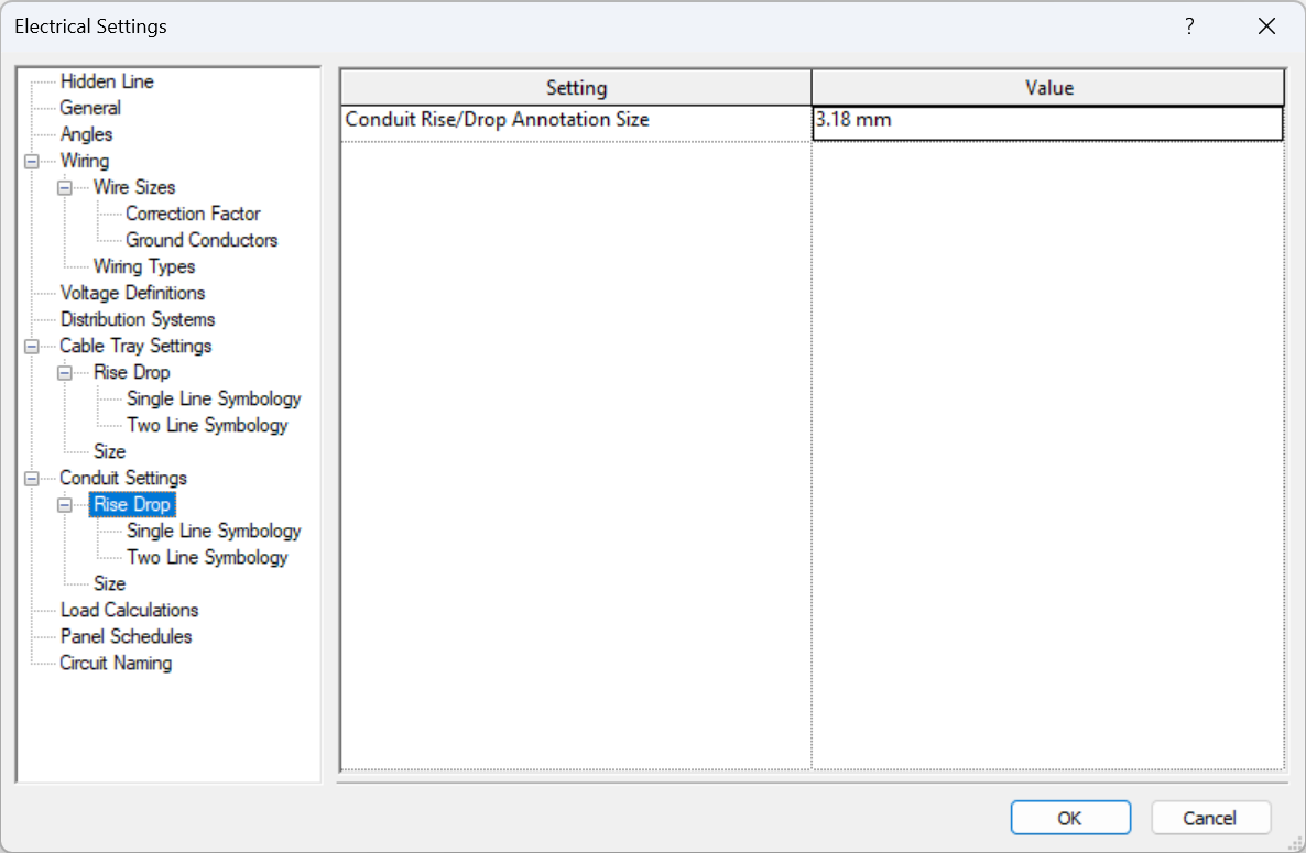
We find the following parameters:
- Conduit Rise/Drop Annotation Size: specifies the plotted size of rise/drop symbols drawn in single-line views, regardless of the drawing scale.
- Single Line Symbology: specifies the rise symbol and drop symbol used in single-line views.
- Two Line Symbology: specifies the rise symbol and drop symbol used in two-line views.
Size (Conduit)
We will also find the subgroup Size:
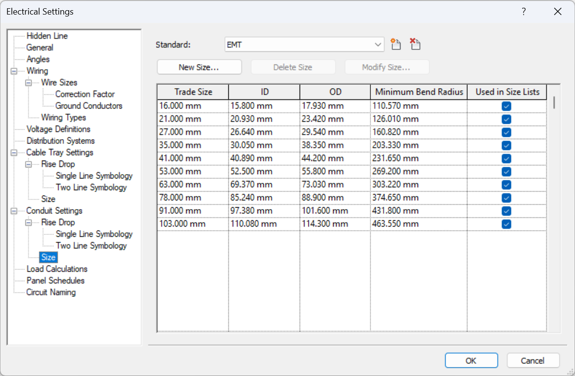
Similarly, we can add, modify or delete conduit sizes, based on the conduit standards with which they are associated.
For each size we must specify the parameters of Trade Size, Inside Diameter (ID), Outside Diameter (OD), Minimum Bend Radius, and indicate whether it is shown in size lists.
Load Calculations
The following section is LOAD CALCULATIONS.
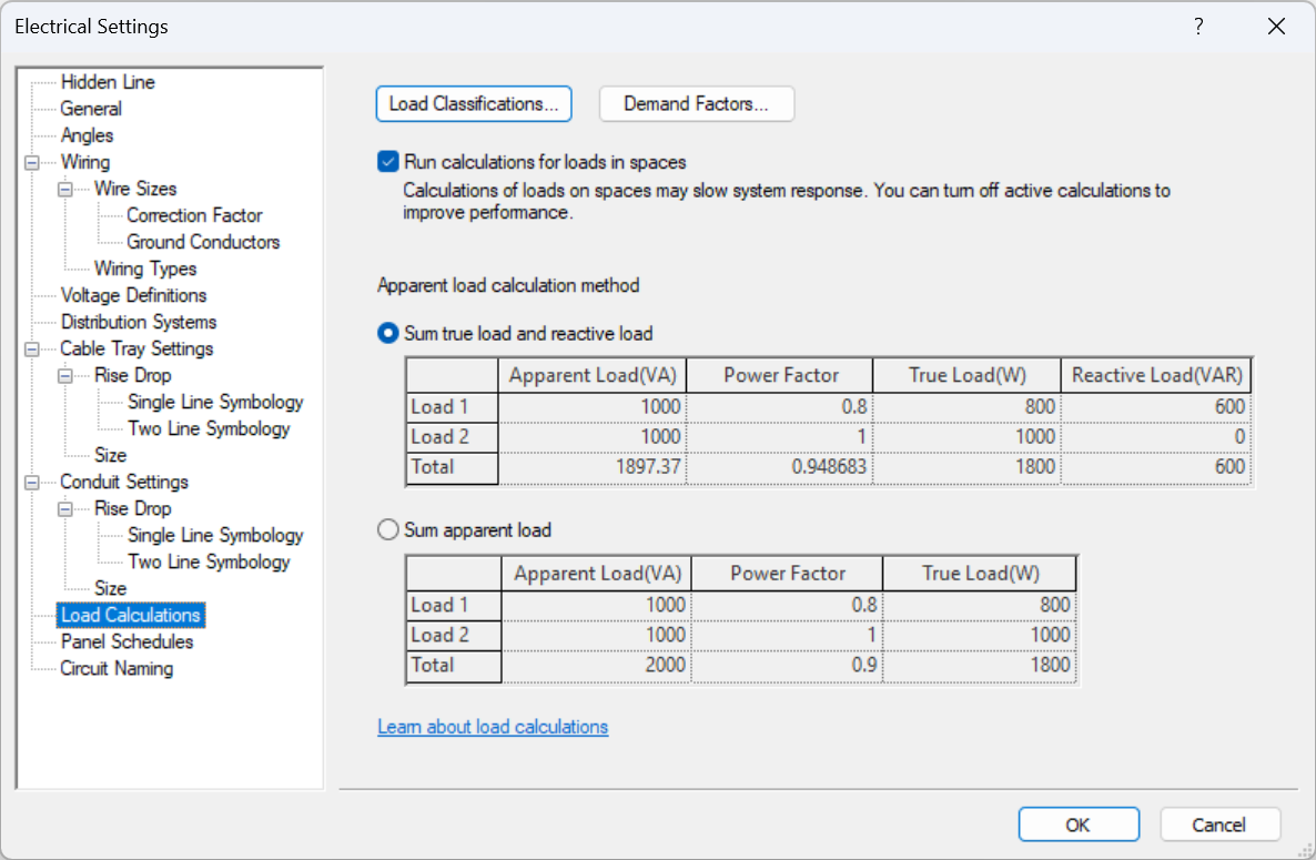
Load classifications contain demand factors, which are applied directly to the circuits, so the modelling sequence is as follows:
We model our elements (with an appropriate load configuration): light fixtures, electrical fixtures and equipments, etc. Then we create the circuit from an element (e.g. a lamp), and assign this circuit with an electrical equipment (e.g. a switchboard). From here on we can assign further equipment to our circuit. Our demand factor will be applied to all elements of the circuit according to the load classification.
So we have to correctly associate the elements and load classifications, as well as the demand factors, to coordinate simultaneity.
3. Electrical Families
To find out everything you need to know about electrical families: the types, their settings and how they can be modelled, we recommend you go to our Electrical Families Guide.
4. Modelling
When we model electrical elements in Revit, we mainly find two types of elements: linear elements (conduits) and point elements (switches, lighting fixtures, electrical equipment, etc.).
All linear elements are system families that are preexistent in the Revit template, similar to walls or pipes. We can configure fittings between these linear elements depending on the level of detail we want to reach in our modelling.
On the other hand, when modelling point elements, Revit's potential lies in the ability to create systems of switches or electrical circuits that connect some elements to others, similarly to a real system.
Routing
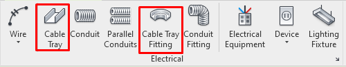
Cable Trays
In Systems>Electrical, we will find the tools to model Cable Trays and Cable Tray Fittings.

General Settings
Before we start modelling cable trays, these must be configured. For that, please go to Section 2 of this guide.
The most important aspect of said sections are Sizes, which can be added, modified or deleted as required:
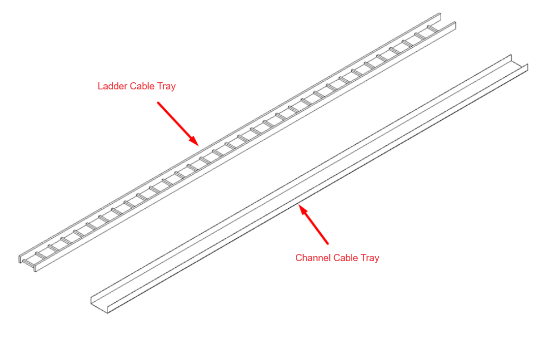
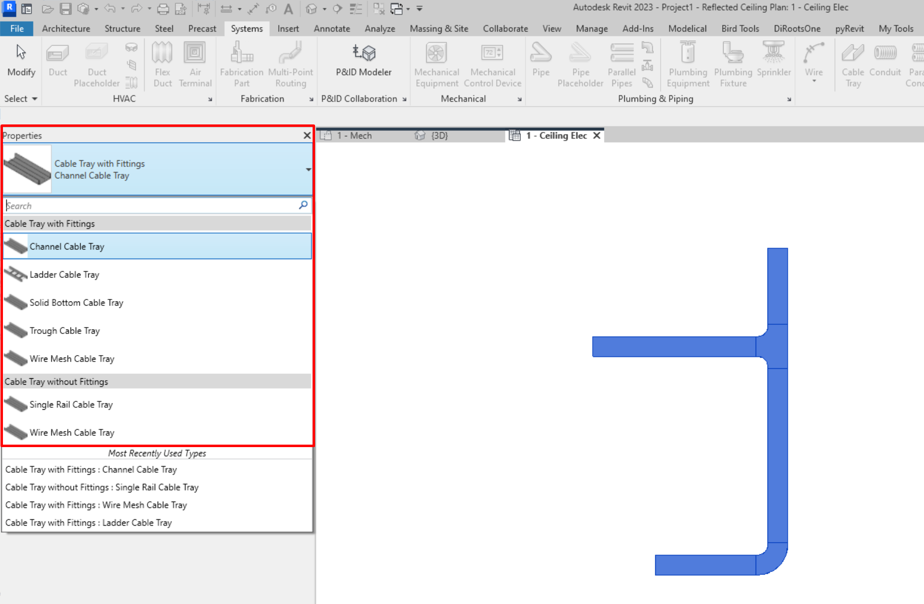
Types of trays
When we begin a project, two main types of tray appear by default: Channel Trays and Ladder Trays. Other types of trays, for example perforated or a wire mesh, will also be represented through one of these two. If necessary, we can model complex types of cable trays using fabrication parts.
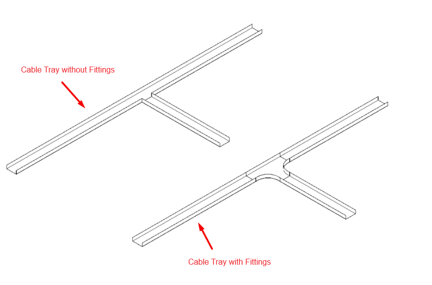
We find two types of Cable Tray families:
- With Fittings: When changing direction or joining cable trays in the model, a type of fitting defined in the cable tray's type properties is automatically created.
- Without Fittings: With this type, no fittings will be created when modelling changes of direction or cable tray joints. This allows the total length of the run to be determined and does not add fittings to the model that do not actually exist.
The use of cable trays without fittings is recommended for complex layouts, as their modelling is more agile than modelling with fittings.
Type Properties
In cable tray type properties, the following can be configured:
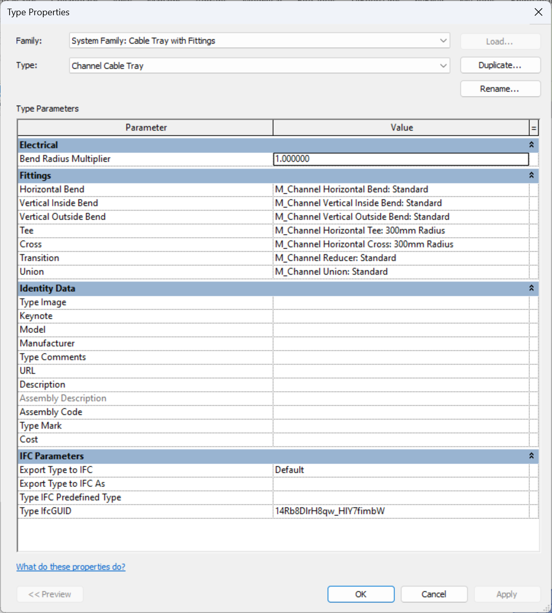
Electrical>Bend Radius Multiplier:
We can modify the "Bend Radius Multiplier". This parameter defines how fittings are automatically modelled. A multiplier value of 1 indicates that the bend radius will be equal to the width of the tray. It is recommended to modify this value according to the real needs and solutions of the layout.
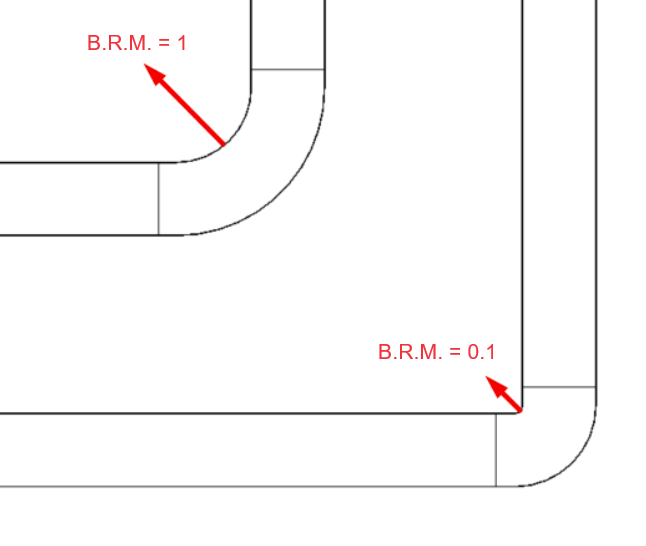
We can also manually change the "Bend Radius Multiplier" of the fitting, both on the drawing or in the properties:
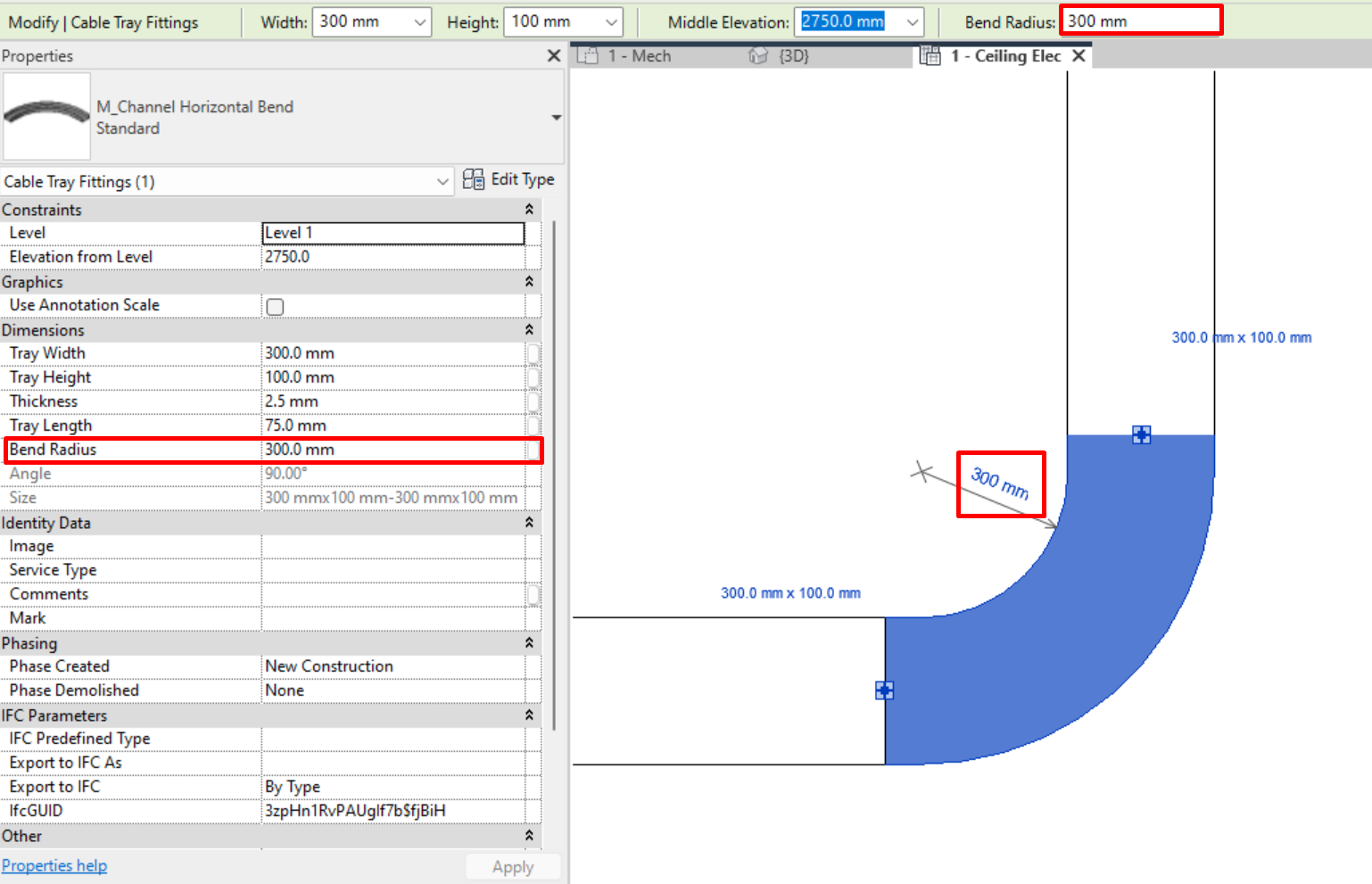
Fittings with lower bending radius are more versatile, but it must be taken into account that cables cannot always make changes of direction with a very sharp bend.
- Fittings:
We can define the default fittings assigned to each type. These will automatically be added as cable trays are modelled. Cable tray fittings are system families, so they can be edited. There are several subcategories for cable tray fittings that define in which selection set they appear:
- Bend (horizontal, vertical interior and vertical exterior): joining of two trays with different orientations.
- Tee: joining of three different trays.
- Cross: joining of four different trays.
- Transition: joining of two different trays with different dimensions.
- Union: junction between two consecutive trays.
More information on electrical tray fittings can be found in section 3.Electrical Families.
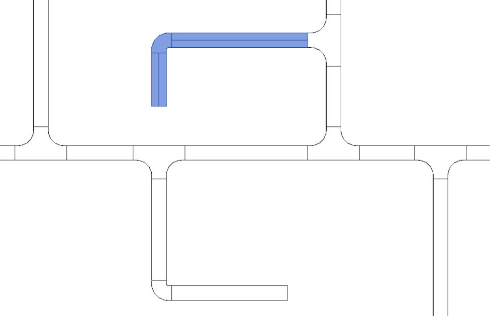
We can change or rotate the fittings to get the layout we need:
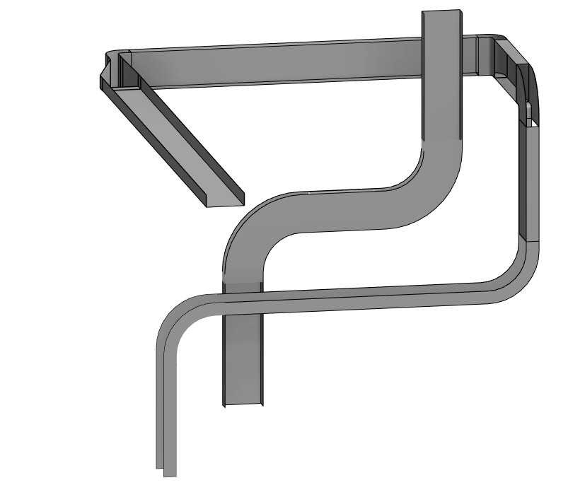
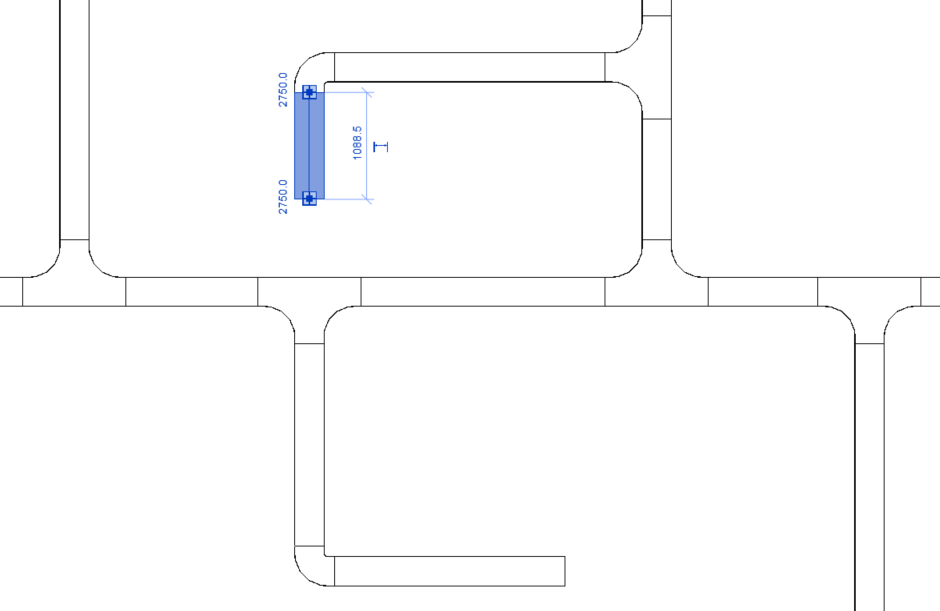
It is useful and recommended to work with sections to rotate cable trays or fittings, as in 3D view it is less agile and inaccurate due to having to recurringly change working planes.
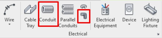
Conduits
In System→Electrical we find the modelling tools ”Conduit” and “Conduit Fitting”:
General Settings
Before we start modelling conduits, these must be configured. For that, please go to Section 2 of this guide. The most important aspect of said sections are Sizes, which can be added, modified or deleted as required:
Types of conduits
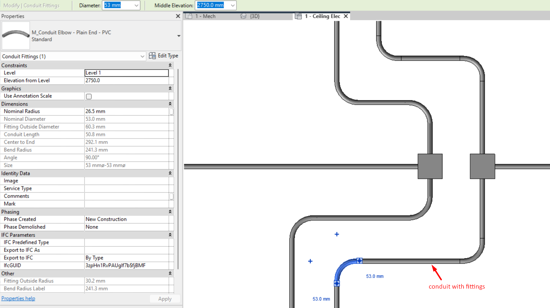
Same as with trays, we find conduit families with and without fittings.
When we model conduits without fittings, fittings are still automatically created, but without a predetermined size, to which we can change the bend radius directly in the work view and in the instance properties, allowing us more versatility in the modelling.
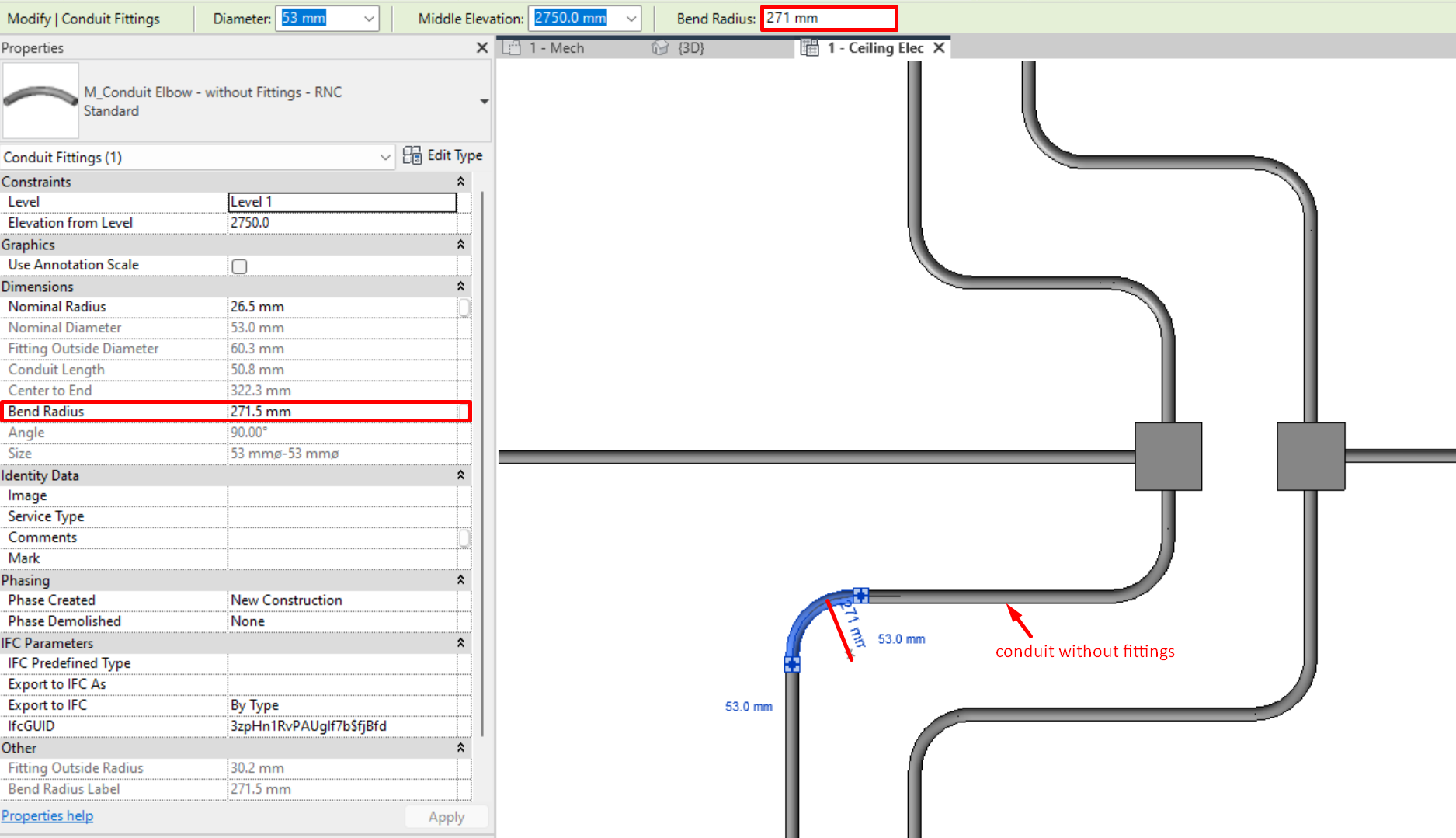
While on conduits with fittings, fittings will have to be modified through the type or family.
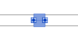
Crosses and unions in T are connection boxes, having 3 or 4 connections.
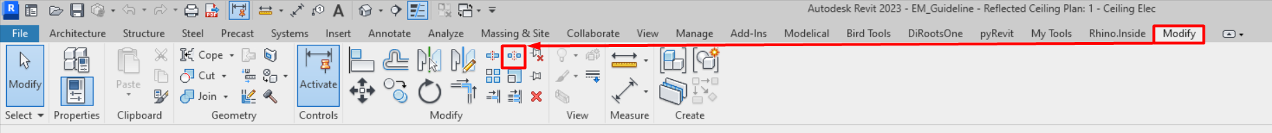
Conduits can be divided in sections by using the Split Element tool , with shortcut “SL”. When we "split element", a conduit union automatically appears that holds the split elements together.

If we “Split with Gap” , the two conduit segments will remain physically separated.

Fittings with lower bending radii are more versatile, but it must be taken into account that cables cannot always make changes of direction with a very sharp bend.
Type properties
In conduit type properties, the following can be configured:
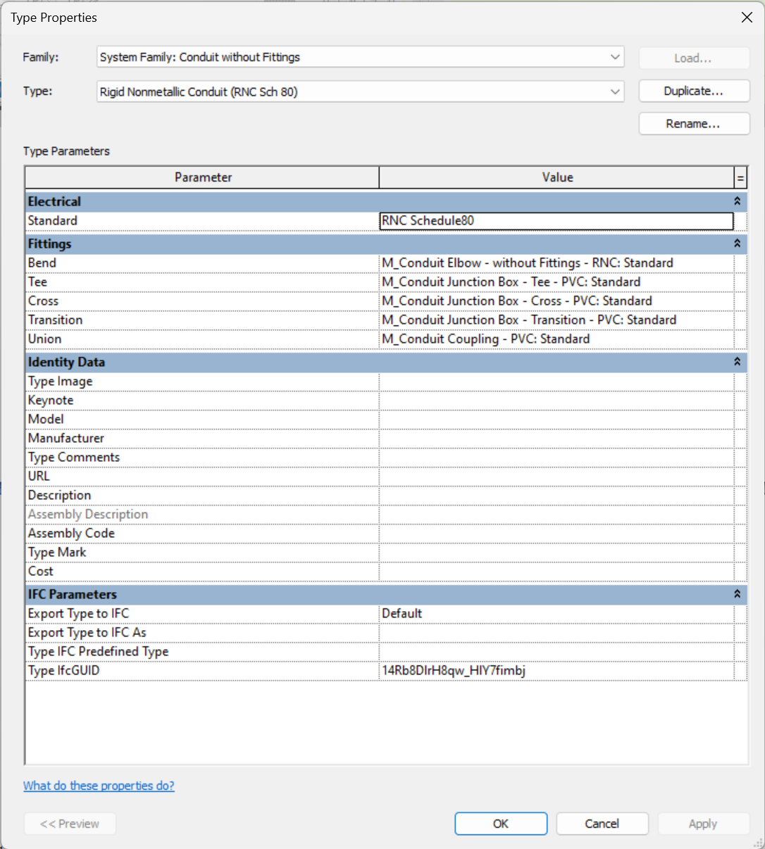
- Standard Type:
The type of “Standard” is the standard to which the previously modelled conduits correspond. We can create as many standard types as we need, always basing the new ones on a preexisting one. The following types come predefined in Revit:
- EMT: metal electrical conduit, used to protect the wiring from external agents, not recommended for use under flooring.
- IMC: metallic electrical conduit with a higher wall thickness than the EMT type, capable of withstanding mechanical damage or industrial impact.
- RMC: rigid galvanised steel metal conduit with notable wall thickness, offering greater mechanical protection in industrial areas.
- RNC Schedule40: rigid non-metallic conduit.
- RNC Schedule80: rigid non-metallic conduit with thicker walls than schedule80.
These standard types are related to materials, with different minimum bending radius and diameter size settings for each type. Therefore, the correct standard has to be chosen according to the needs and requirements of the project.
- Fittings:
We can also define the fittings assigned to each type. These are automatically added as the conduits are modelled. Conduit fittings are not system families, so new families can be loaded into Revit. There are several subcategories for conduit fittings that define the selection set they appear in:
- Bend: joining of two conduits with different orientations.
- Tee: joining of three different conduits. Usually resolved with a connection box.
- Cross: joining of four different conduits.Usually resolved with a connection box.
- Transition: joining of two conduits with different sizes. Usually resolved with a connection box.
- Union: junction between two consecutive trays.
More information on electrical conduit fittings can be found in section 3.Electrical Families.
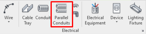
Creating Parallel Conduits
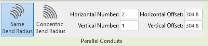
“Parallel Conduits” is a tool that allows us to create parallel conduits by resolving their unions with the same radius of curvature or by making them concentric.
This option is recommended when we have to model several parallel conduits as it saves time, always only as long as we have the spaces through which the installation runs well delimited and controlled.
Allows us to create parallel running conduits with a determinate horizontal and vertical numbers, applying a determined offset to the axis of the conduit.
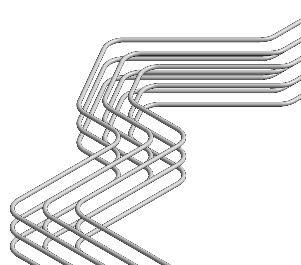
We can select one conduit or the entire routing by using the tab key, as usual in element selections:
Conduit connections to Cable Trays
Conduits can be connected to cable trays laterally, or on its upper and/or lower face.
We must be careful when modelling a conduit that crosses close to a cable tray, under or over it, as it creates automatic non-contact connections between the cable tray and the conduit.
Routing edition
Visualisation Filters
In Revit there are no cable trays or conduit systems as there are for pipes and ducts, so it is important to use different types for the different supplies of the installation. To improve the visual identification and fluidity in the modelling of these elements, the best strategy is to create view filters for each type of cable tray or conduit we have.
The process for creating a filter by type name is explained below:
- We create a new filter on: Visibility/Graphic Settings→ Filters → Add→ Edit/New→ New
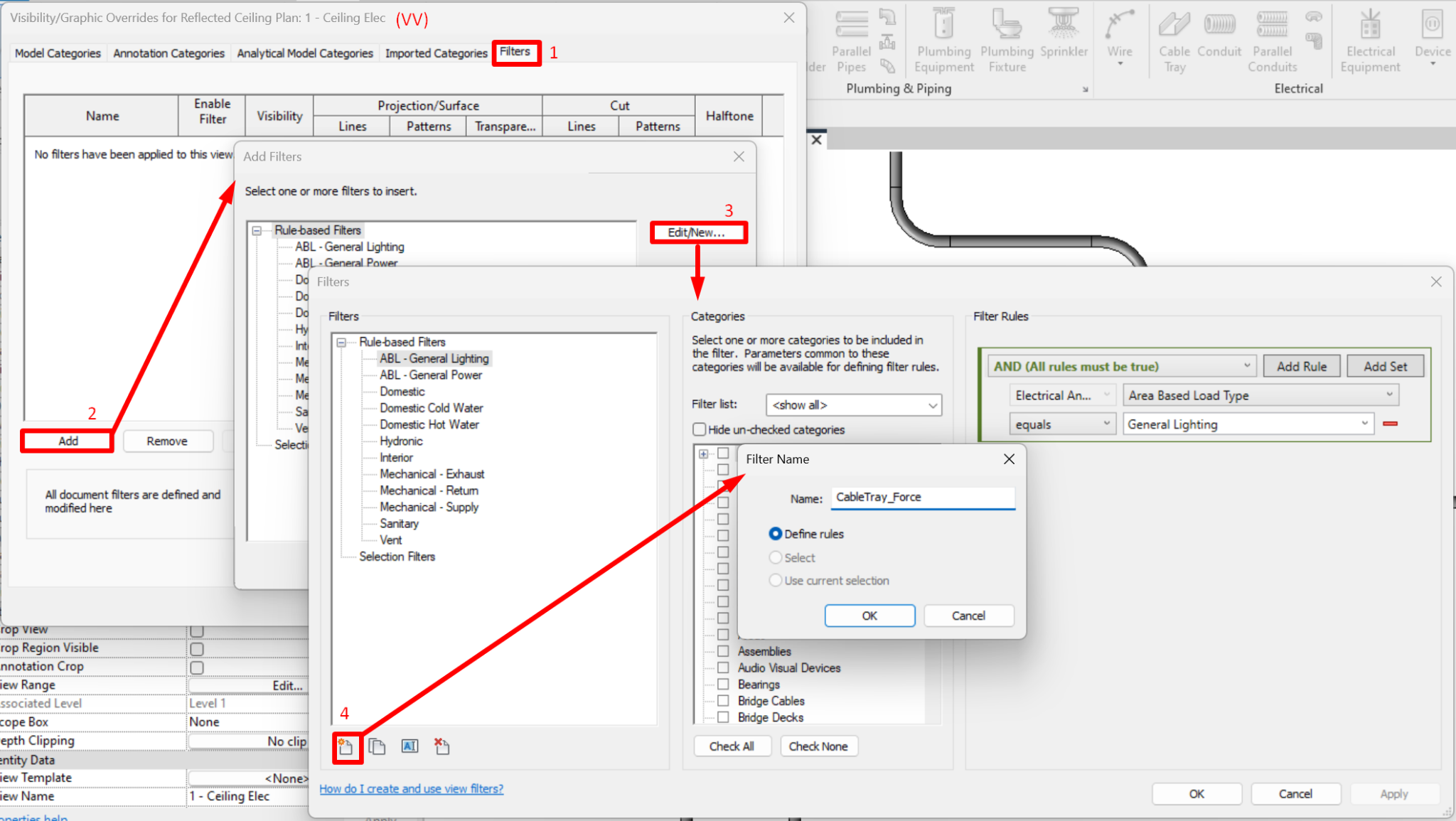
- We select the categories we want the filter to affect, in this case: Cable Trays and Cable Tray Fittings.
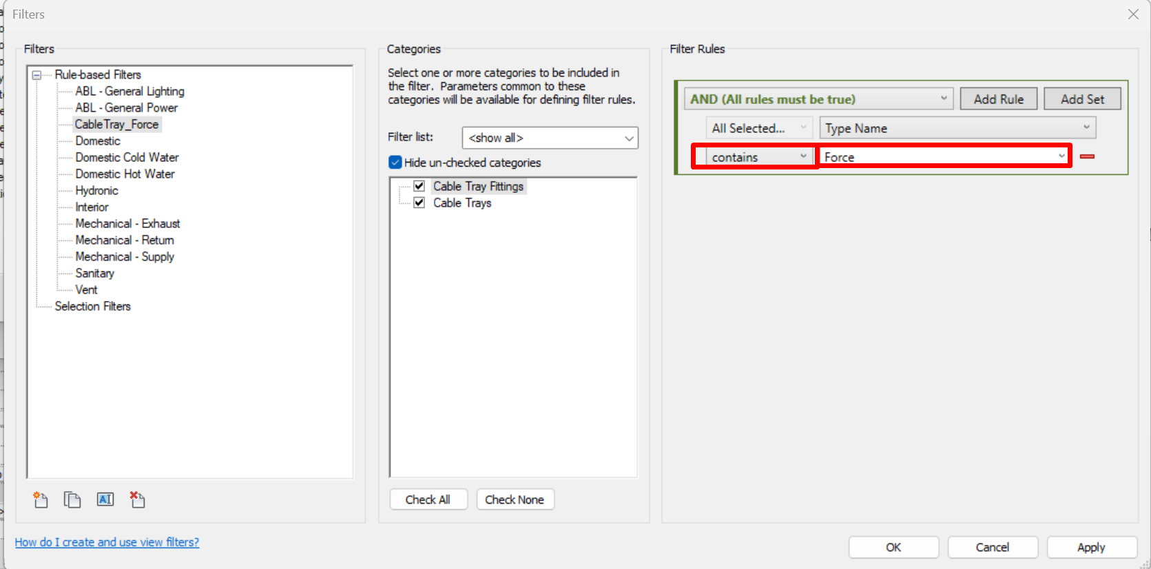
Then we apply the filter rules, in which we select the parameter 'Type name' > contains > [Type name]. In the picture we can see an example for a cable type called 'Force'. It is recommended to use the selector 'contains' rather than 'is equal to', as it is less likely to give an error, especially when the trays are in a link.
- Finally we add the filter and modify the fill pattern graphics according to how we want the cable trays to be displayed in the view.
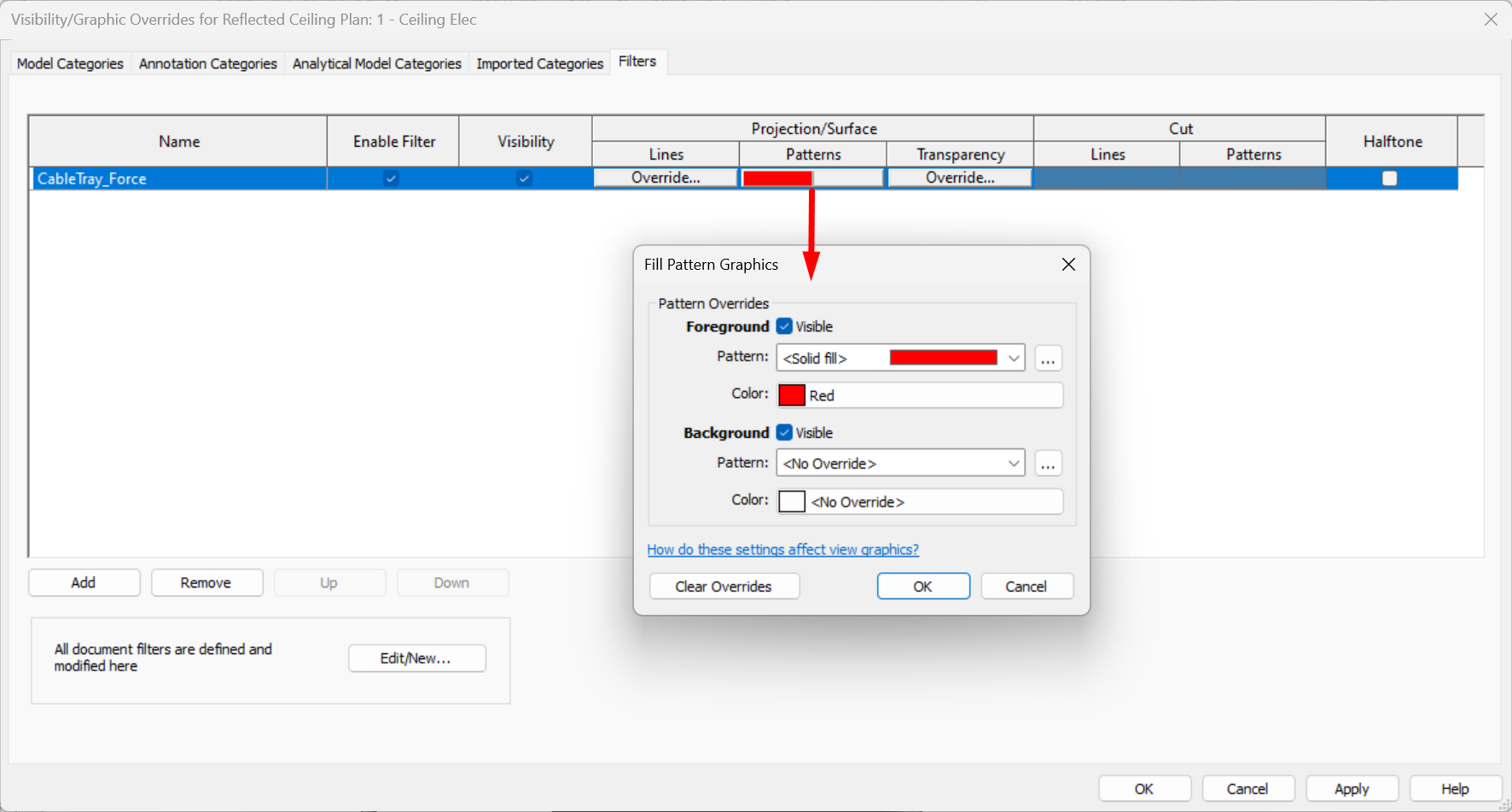
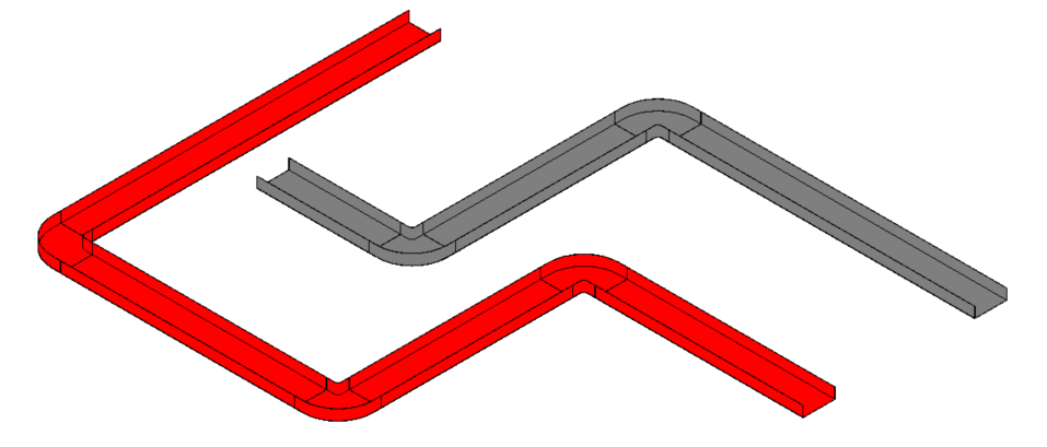
This way, each tray will be displayed differently in the view according to its type name, which will represent the need of the system.
It is important to establish the nomenclature of the different systems prior to modelling so that the type names coincide and the filter is applied correctly. It is recommended that this nomenclature is indicated in the BEP.
For conduits, the same solution would apply, but with the categories "conduit" and "conduit fittings".
Group Selection
Revit allows different ways of selecting cable trays, conduits and fittings depending on the initial element we select and the number of tabulations we make.
To make a selection of the system of cable trays and conduits, it is useful to use the tab key on the keyboard.

- By placing the mouse pointer over an element and selecting it, without pressing any key, we only select this element.
- If we place the mouse pointer over an element and press the "TAB" key once, we select the path up to the Tee, without selecting the fitting.
- If we place the mouse pointer over an element and press the "TAB" key twice, we select the path up to the Tee, including it.
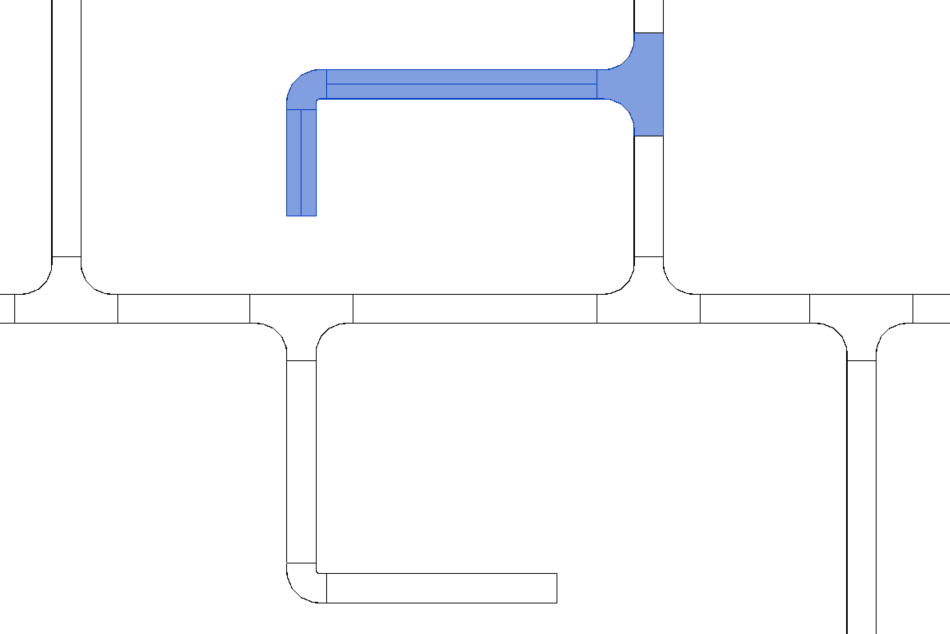
- If we place the mouse pointer over an element and press the "TAB" key three times, the entire connected path is selected.
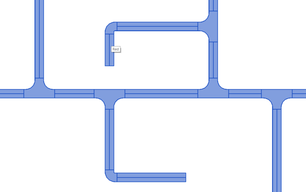
- If we select one element, then place the pointer over another and press "TAB" once, the shortest path from the first to the second selected element is selected.
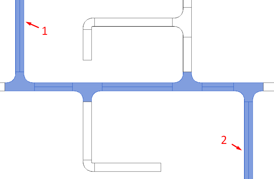
- Placing the mouse pointer over an element and pressing "TAB" four times would select the system. This will be covered in the section on switch systems and electrical circuits.
Tray type change
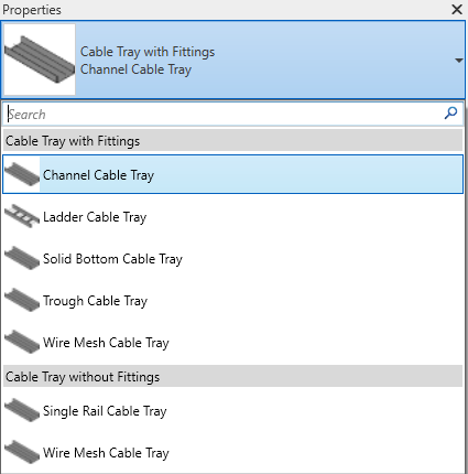
Finally, if we want to change the type of cable tray or conduit of a specific route, including fittings, we can do so by selecting the elements and selecting "Change type":
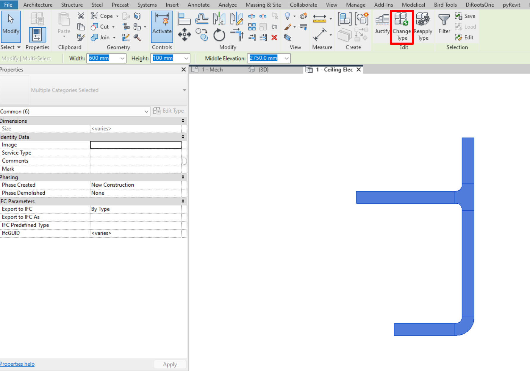
A drop-down menu will be activated in the properties box, where all the types of trays or conduits will appear, which we can select to change the selected elements.
Switch Systems
Switch Systems are used to connect lighting fixtures to their corresponding switch.
Elements of a Switch System
To create a switch system we need two types of elements: switches and light fixtures.
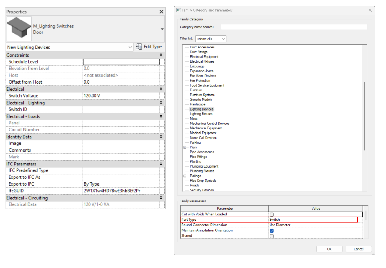
- Lighting Devices → Switch
This is an element within the family category “Lighting Device” which has “Switch” defined as its “Part Type” in the Family Category and Parameters dialogue.

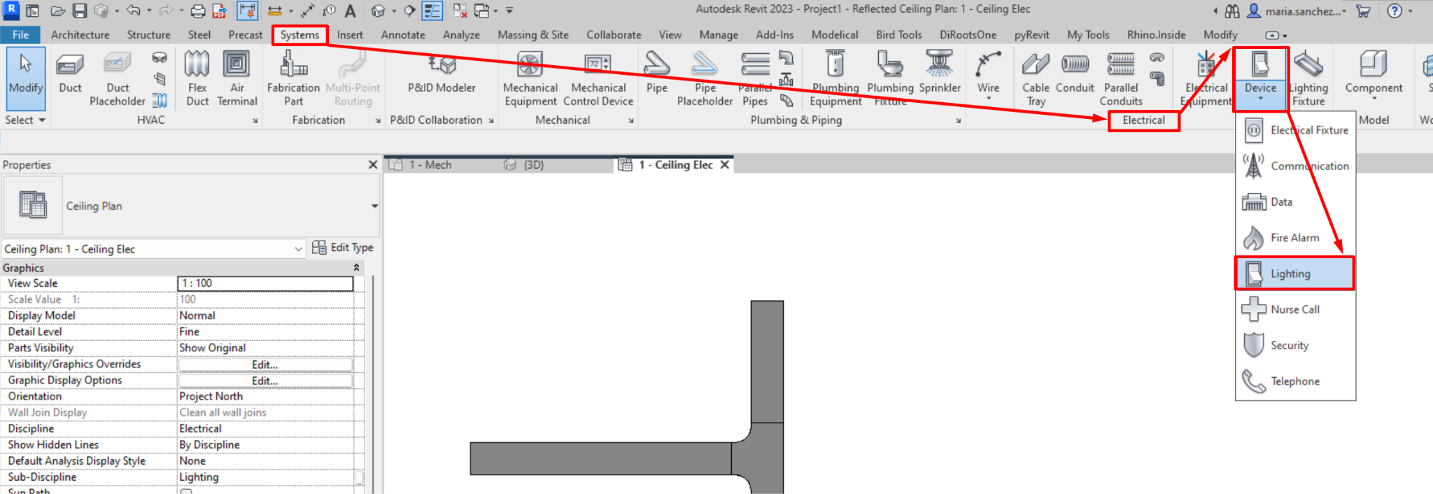
We can model a switch by accessing: Systems → Electrical →Device → Lighting
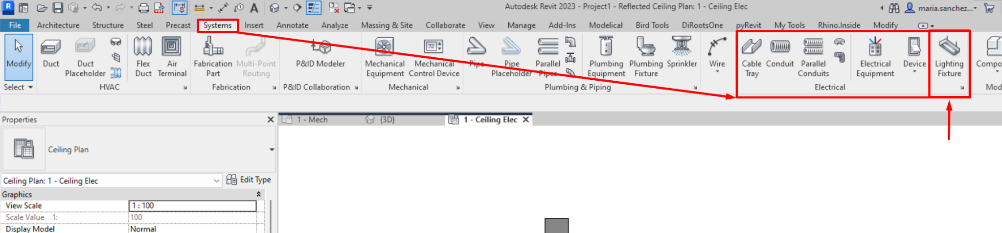
- Lighting Fixture
This is an element of the category “Lighting Fixture”.
To model a lighting fixture, we must head to: Systems → Electrical → Lighting Fixture
Switch System Creation
To create a Switch System we must follow these steps:
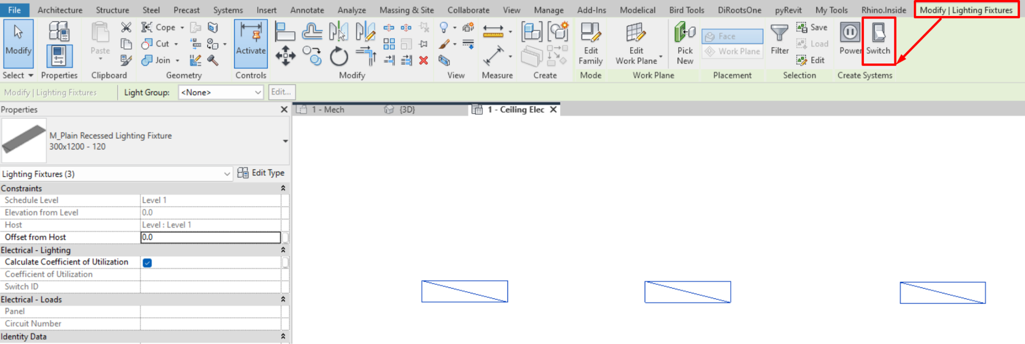
- Select the lighting fixture/s that are going to belong to the system to be created, and go to: Modify/Lighting Fixtures→ Switch.

This option will not appear if the fixtures already have an associated system.
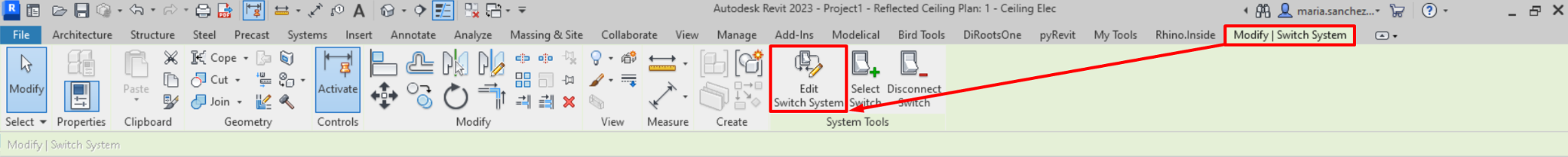
- Add the switch to the system by going to : Modify/Switch system → Select switch.
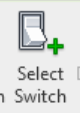
- And finally we select the switch that we want to associate to the system.
We can add as many lighting fixtures as we need to a switch system; however, only one switch can be associated with it.
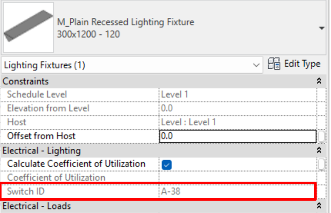
When the system is selected, the "Switch ID" parameter appears in its properties, which is associated with an instance parameter of the lighting device (switch) related to the system. It also appears in the properties of the lighting fixture associated with that system.
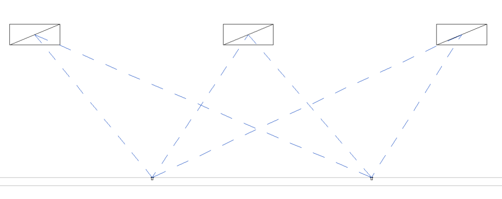
Switch System Selection
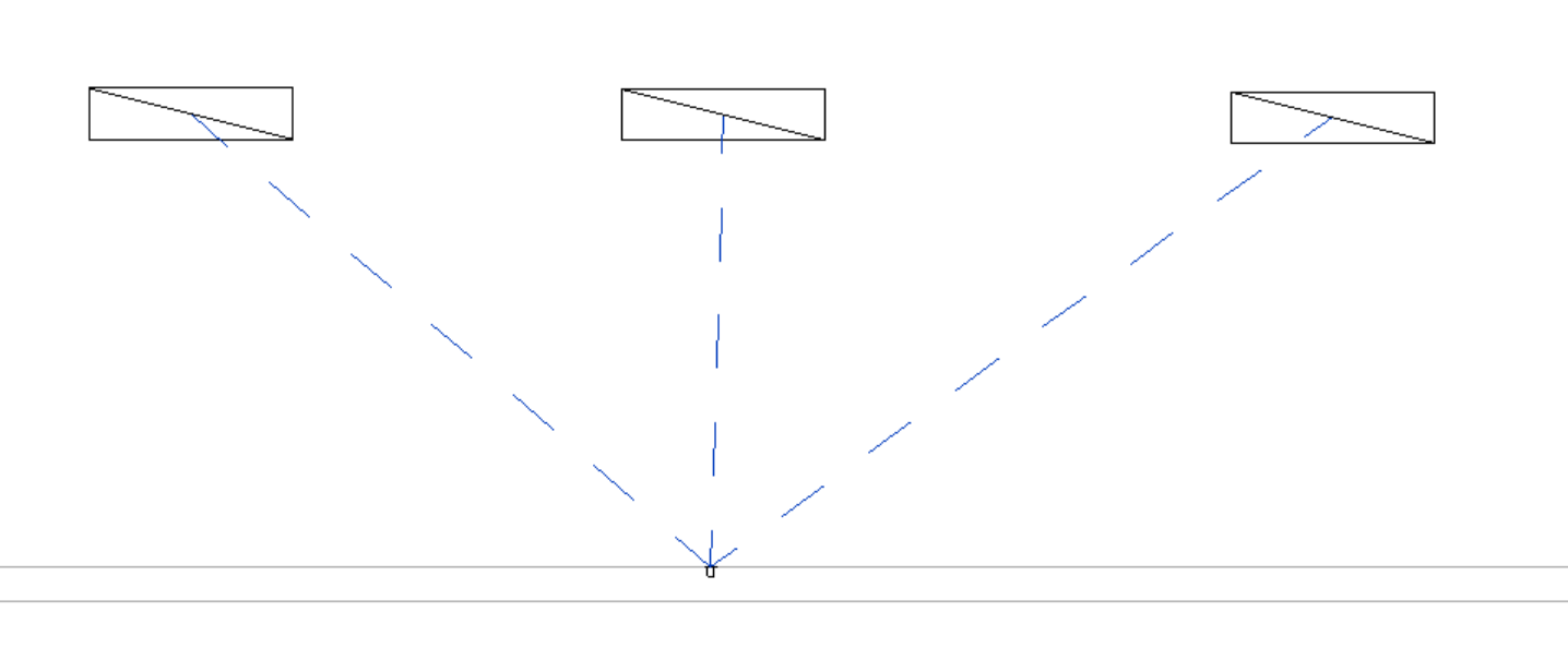
To select the switch system, use the "TAB" key on the keyboard. Follow the steps below:
- Place the mouse pointer on an element of the system, it can be a lighting fixture or the lighting device (switch).
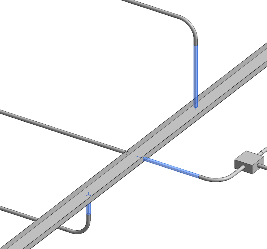
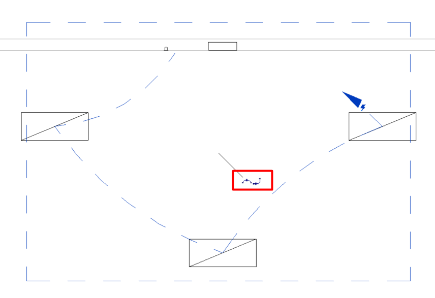
- Press the tab key on the keyboard, so that the switch system is highlighted by blue dashed lines that connect the switch with each of its associated lighting fixtures.
- Select the switch system by pressing the left mouse button.
Switch System Editing
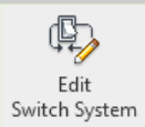
When we have selected a switch system we can access "edit switch system".
We find the following options:
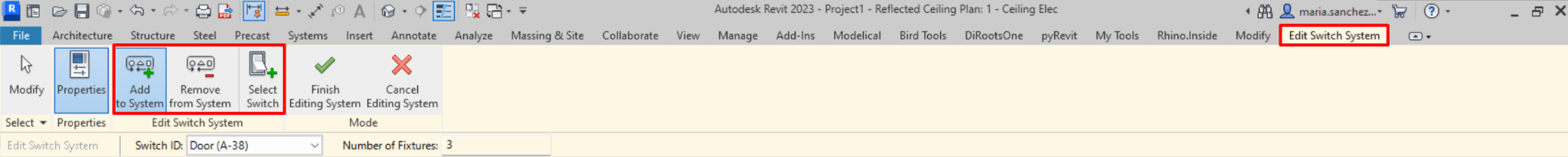
- Add to System: Allows us to add new lighting fixtures to our switch system.
- Remove from System: Allow us to remove lighting fixtures currently associated to the switch system. If we remove all fixtures, the system itself is deleted as well.
- Select Switch: allows us to select the switch that will be associated to the system. If there is already a switch associated to the system, the last one selected will replace it, as there can only be one switch per system.
Electrical Circuit
The function of electrical circuits is to connect different electrical devices, such as switchboards, lighting fixtures and sockets, to conforman electrical system.
Electrical Circuit Creation
We can create electrical circuits that connect compatible electrical devices and light fixtures and associate them to an electrical equipment panel. To create an electrical circuit, these steps must be followed:
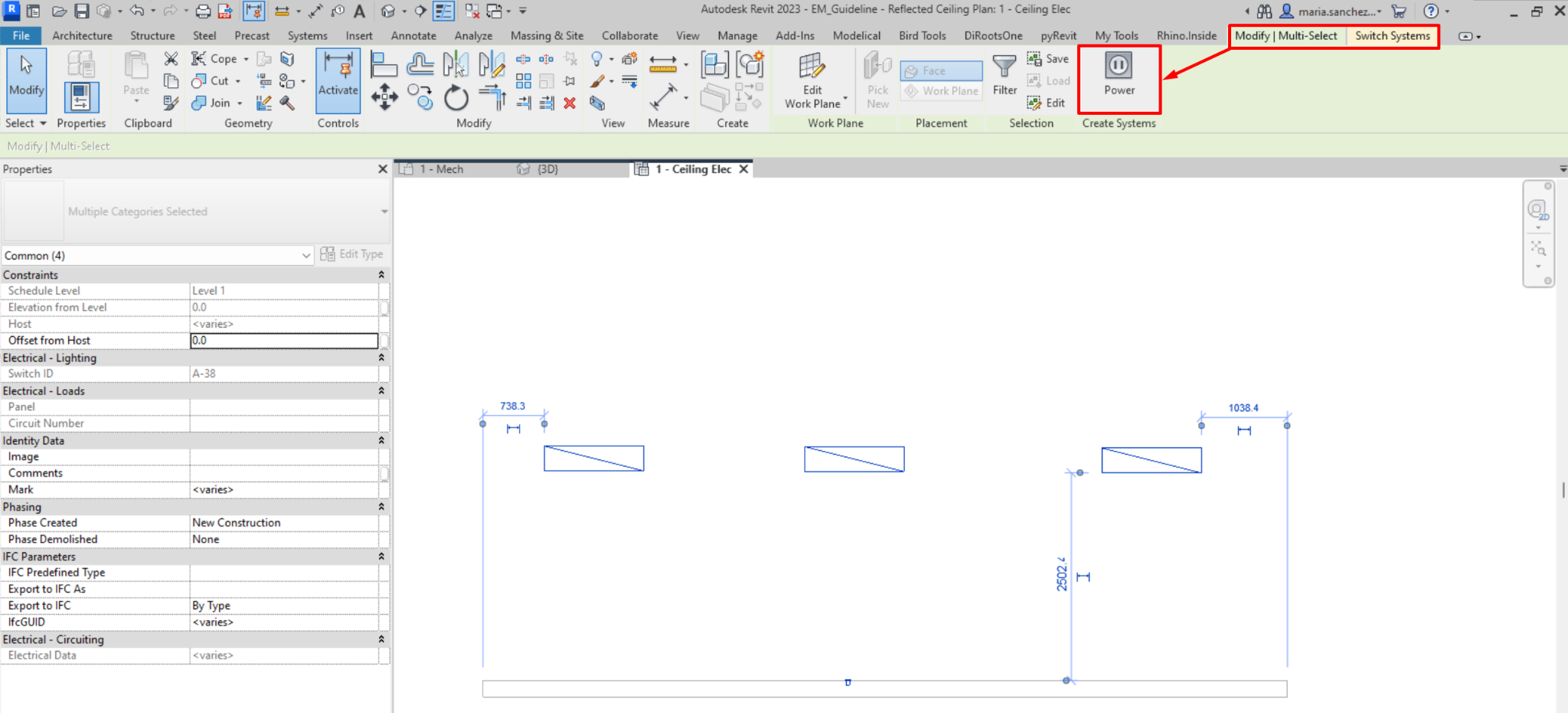
- If we select the elements (electrical devices or luminaires) that are compatible and that we want to assign to the same circuit, the option "Power" will appear in Modify/Multiple selection → Create system → Power.

- To create an electrical circuit, it is sufficient to select a single compatible element.
- Once the circuit has been created we can assign an electrical panel, in "Modify/Electrical Circuit → System tools → Select panel".
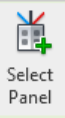
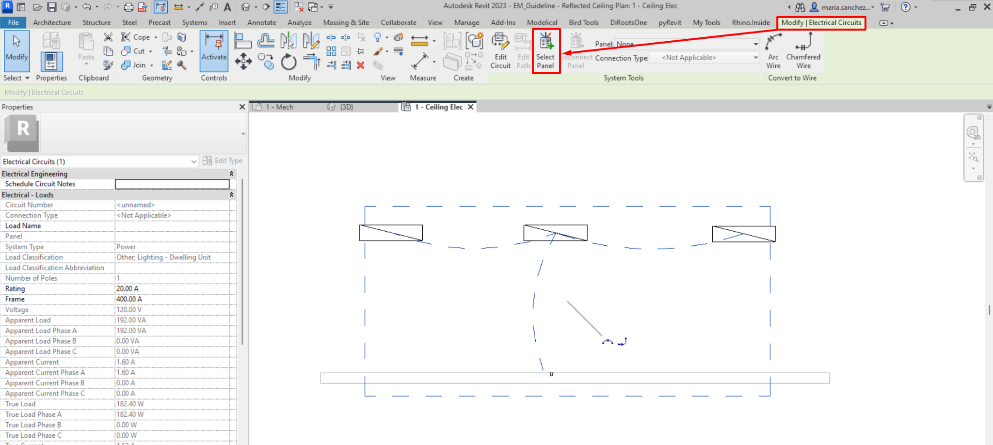
When we select an electrical device or lighting fixture in the model, the option to create a system of the type that matches the properties of the connector of the selected family is activated. If there are several connectors in the selected device, there will be a button for each one. For example:
When we select a lighting fixture, we will get the option to create both a Power System or a Switch System. The latter is developed in the previous section “Switch Systems”.
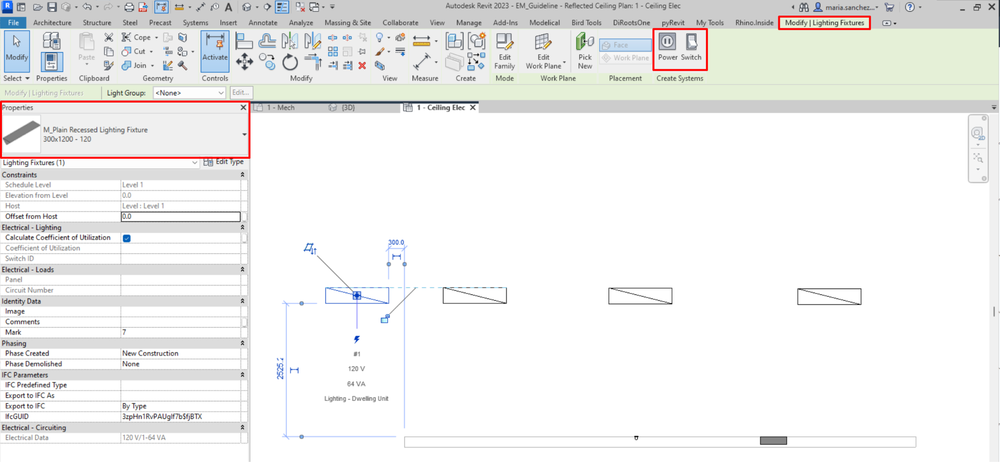
On the contrary, if we select an electrical device or equipment, we will only get the option to create a Power System.
The correct procedure for modelling electrical circuits in Revit for documentation should be:
- Establish load classifications.
- Establish demand factors.
- Assign demand factors to load classifications.
- Assign load classifications to family connectors or to families.
- Assign distribution systems to equipment.
- Connect installations to equipment.
- Generate panel schedule templates.
- Create panel schedules.
- Manage panel loads and circuits.
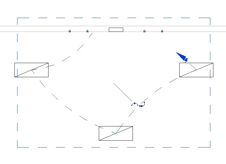
Electrical Circuit Selection
Same as with switch systems, to select the power system, you have to use the "TAB" key on the keyboard. Follow the steps below:
- Place the mouse pointer over an element of the system, which can be a lighting fixture, electrical appliance, lighting device or electrical equipment.
- Press the tab key on the keyboard, so that the electrical system is highlighted by blue dashed lines linking the associated elements.
- Select the electrical system by pressing the left mouse button.
Electrical Circuit Editing
When we have an electrical circuit selected, we can press on “Edit Circuit”.
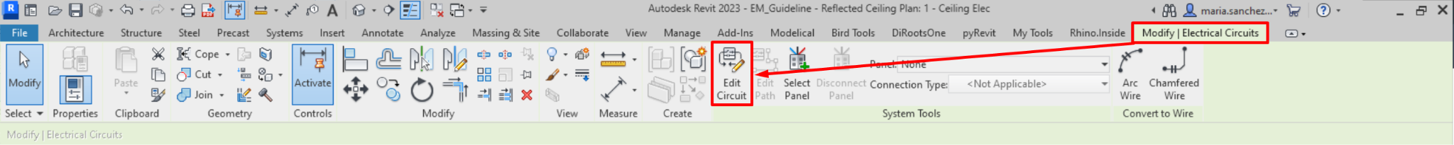
We find the following options:
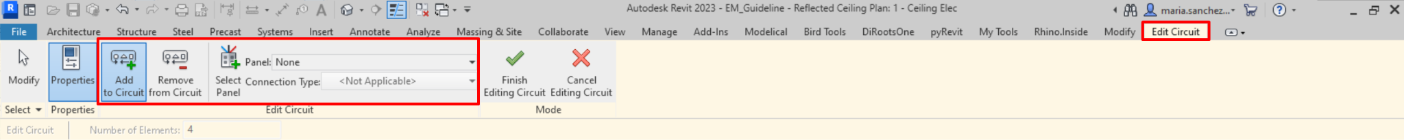
- Add to Circuit: Allows us to add new elements to our electrical circuit.
- Remove from Circuit: Here we can delete elements that are associated with the electrical circuit. If we remove all the elements of the circuit, the circuit is also removed.
- Select Panel: In this option we can select the distribution panel or transformer that is associated with the electrical circuit (must be compatible). If there is already one associated to the circuit, the last one selected will replace it, as there can only be one panel per circuit. However, a panel can be associated with several electrical circuits.
- Panel: Here, as in "select panel", we can select the distribution panel we want to associate to the circuit. But in this case we do not select it in the model, a list appears from which we choose it. Only the panels compatible with the electrical circuit will appear in the list, sorted according to their distance from the circuit.
- Connection Type: In this option we can select whether the circuit is connected to a circuit breaker or to lugs. By default "Breaker" will be selected, but if we want to connect a main panel to a secondary panel with "lugs" we must specify this type of connection. We can activate or deactivate the parameter "Feed through Lugs" of the panel by selecting it, in the instance properties → Electrical - Circuiting→ Feed throughLugs.
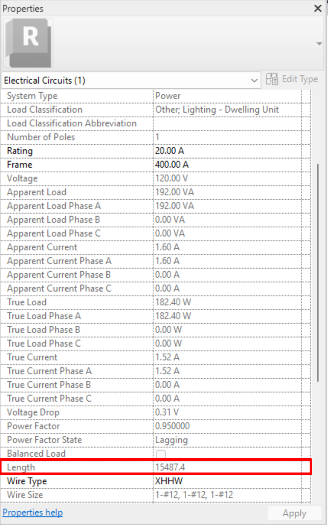
Circuit Properties
We can see the properties of the electrical circuit if we activate the "properties" button when editing a circuit. Modify / Electric circuits → Edit Circuit → Properties

If we have the properties panel active, we will be able to see the properties of the selected circuit without having to “Edit Circuit”.
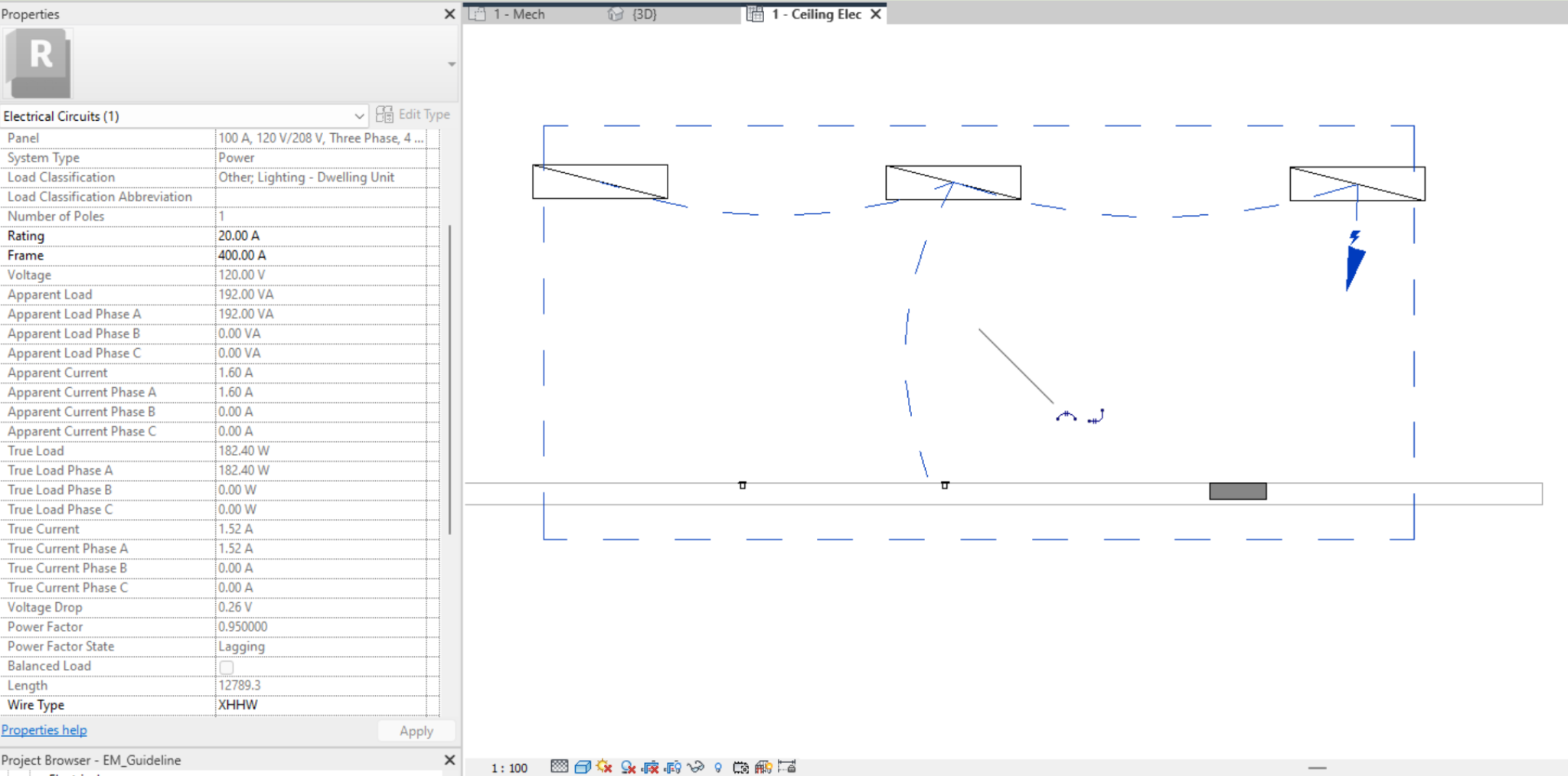
Most of the data comes from the characteristics of the electrical connector and the distribution system.
The software takes the load classification of the circuit components to calculate the apparent and active load, as well as the voltage drop and cable size.
We can modify:
- Connection Type: As previously commented on the Circuit Editing section, displays the connection type for panel-to-panel connections, either Breaker (Default) or Feed Through Lugs.
- Load Name: Name that will appear as the Load Name in the panel schedule for the panel where this circuit is connected.
- Rating: Current rating for the circuit. The current rating for the circuit is used to calculate the wire sizing. By default 20 Amperes. A warning displays when the load for a circuit exceeds 80% of the specified value for Rating.
- Frame: Frame rating for the circuit. The maximum value that a breaker's trip can be set to.
- Wire Type: Type of wire used for the circuit. You can select a wire type for the circuit from the types specified in the Electrical Settings dialog. The type of wire selected for the circuit affects the wire sizing calculation.
Wiring
In Revit we cannot model wiring, but we can represent it in a plan view. When we have an electrical circuit selected, we have the option to 'Convert to Wire', which can be arc or chamfered.
To do this we must go to the tab Modify / Electrical circuits → Convert to Wire → Arc Wire or Chamfered Wire.

Similarly, these two options appear as an icon with the selected circuit in the centre of it.
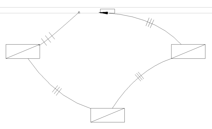
- Arc Wire: With this option, the wiring is represented by arcs that connect the elements that make up the circuit. It is customary to use this option because it is the most common representation.
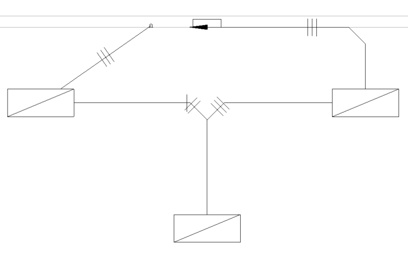
- Chamfered Wire: With this option, the wiring is represented by straight lines connecting the elements that make up the circuit.
Modifying the wire
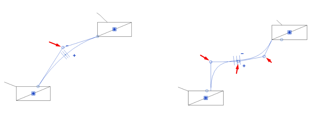
We can modify the curvature of a wire by moving the grips that appear when it is selected. We can insert or delete wire vertices by right-clicking on the selected wire, which gives us more control over the wire's layout.
Wire Tick Marks Properties
When we select a wire in the view, the parameter “Tick Marks” appears in its instance properties. Through these properties, we can control the visualisation and number of conductors in the circuit.
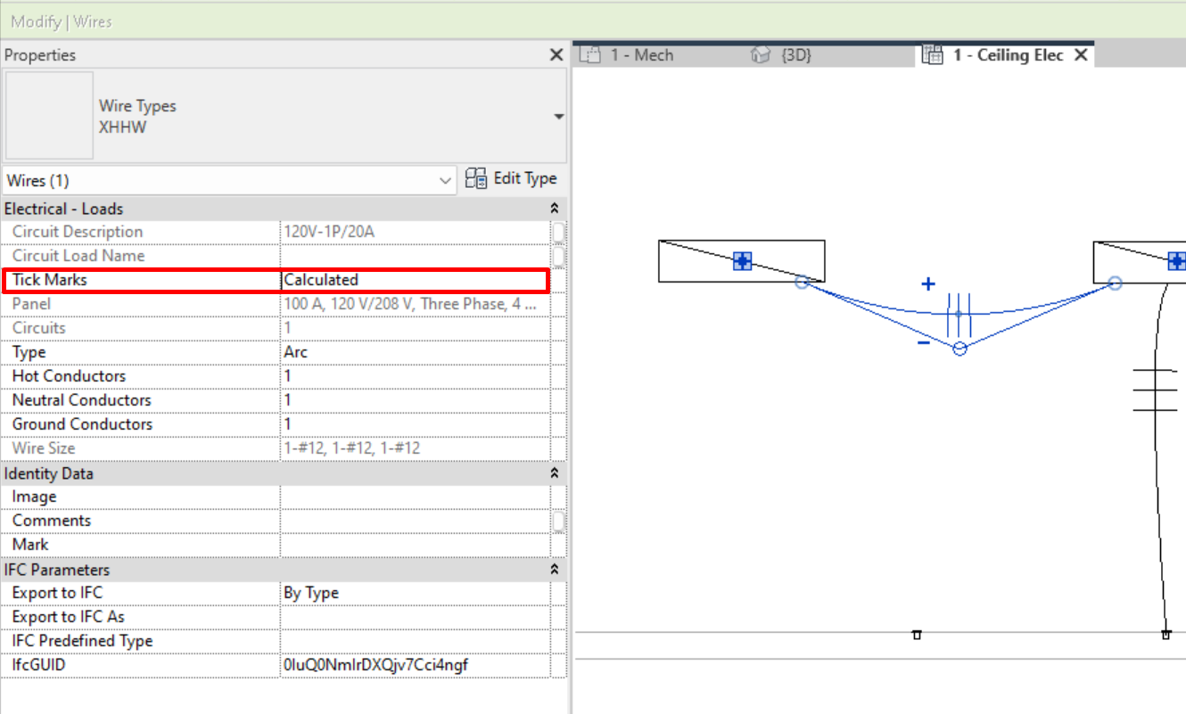
There are three options for the Tick Marks parameter:
- Calculated: The number of conductors is determined by the properties of the circuit and the distribution system.
- On: Displays tick marks on the selected wire, indicating the number of conductors loaded in the wire.
- Off: Disables the display of tick marks.
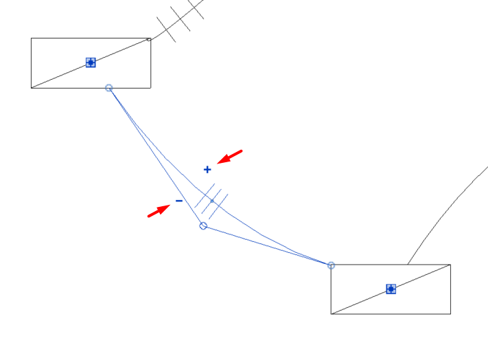
We can also increase or decrease the number of each charged conductor through the "+" and "-" symbols which appear when selecting the wire in the view.
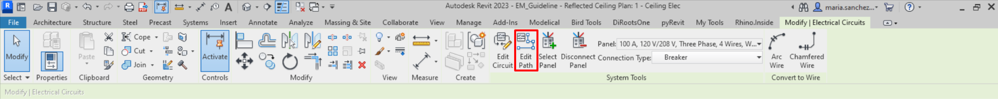
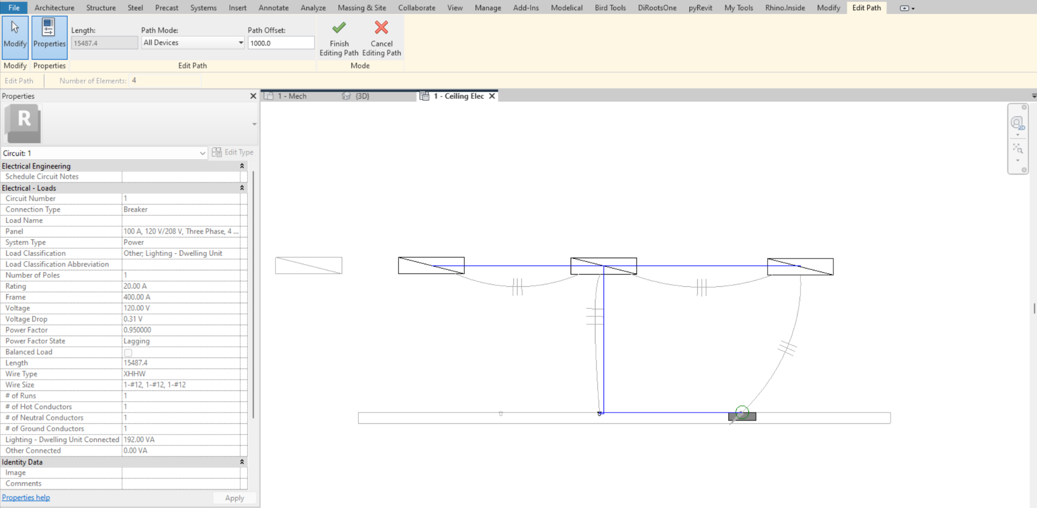
Edit Path
We can specify the path of the circuit to match the reality of the layout so that the actual length of the wire is calculated more accurately, including the vertical path to the circuit elements, which is directly related to the calculation of the voltage drop.
To edit the path, with the electrical circuit selected, we have to access: Modify / Electrical Circuits → Edit Path.
By accessing "Edit Path" we can edit the polyline related to the path that has been automatically drawn, modifying it and adding control points according to our needs.
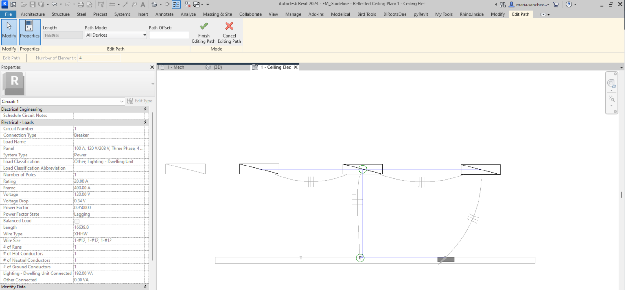
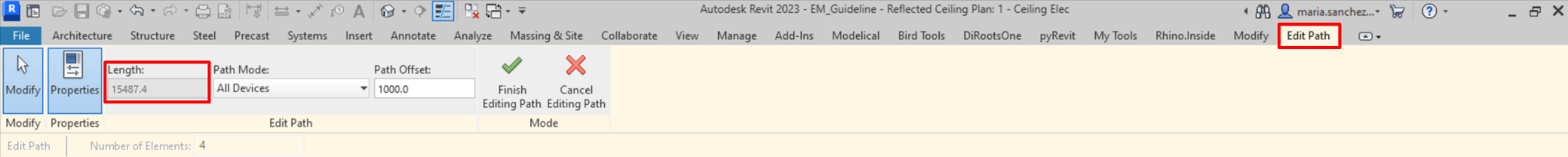
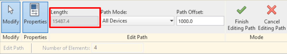
In Edit Path we can modify the Path Mode and the Path Offset:
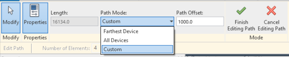
- Path Mode: We can select one of three pre existing options:
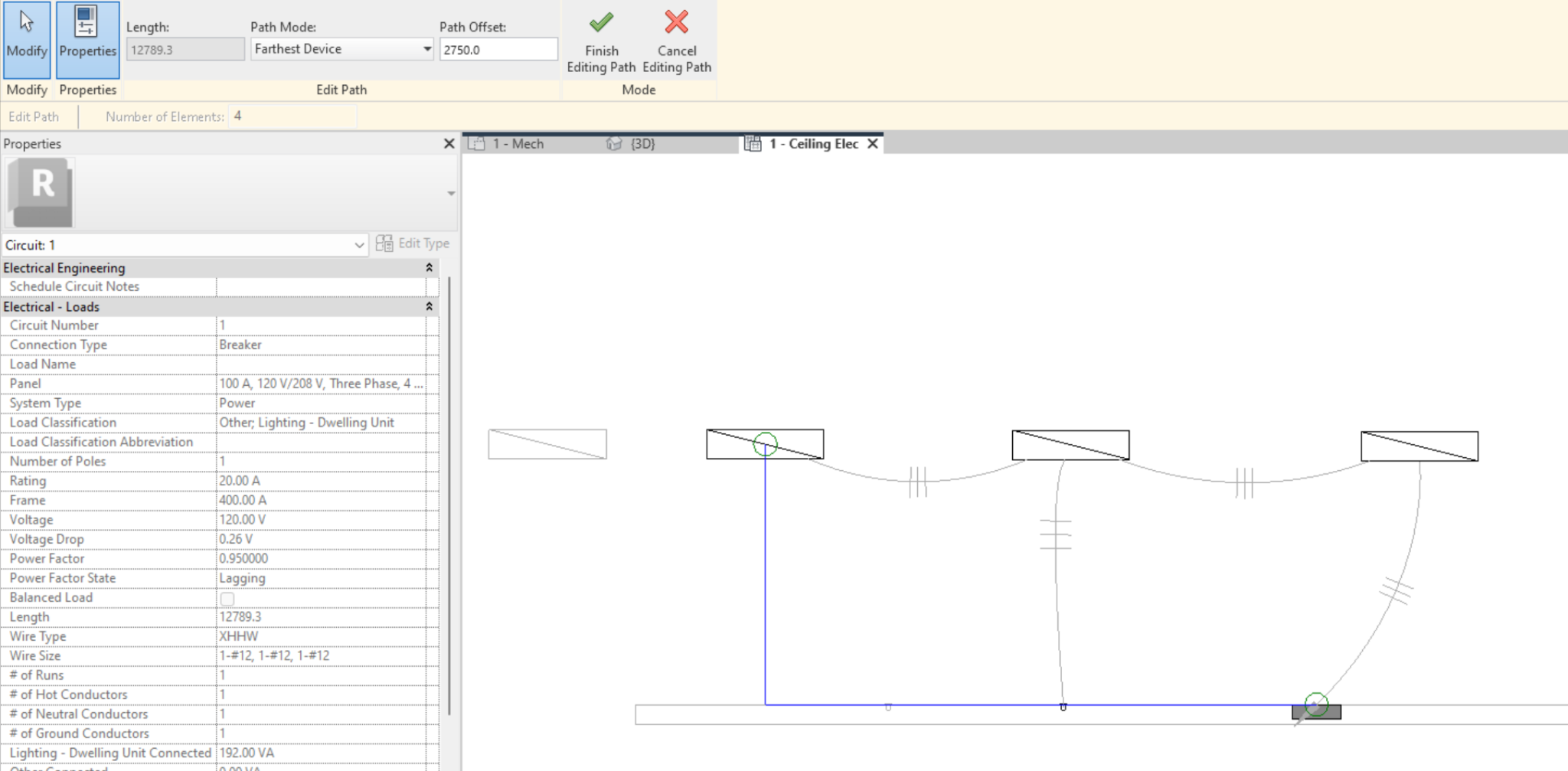
- Farthest Device: shows the path to the farthest device only.
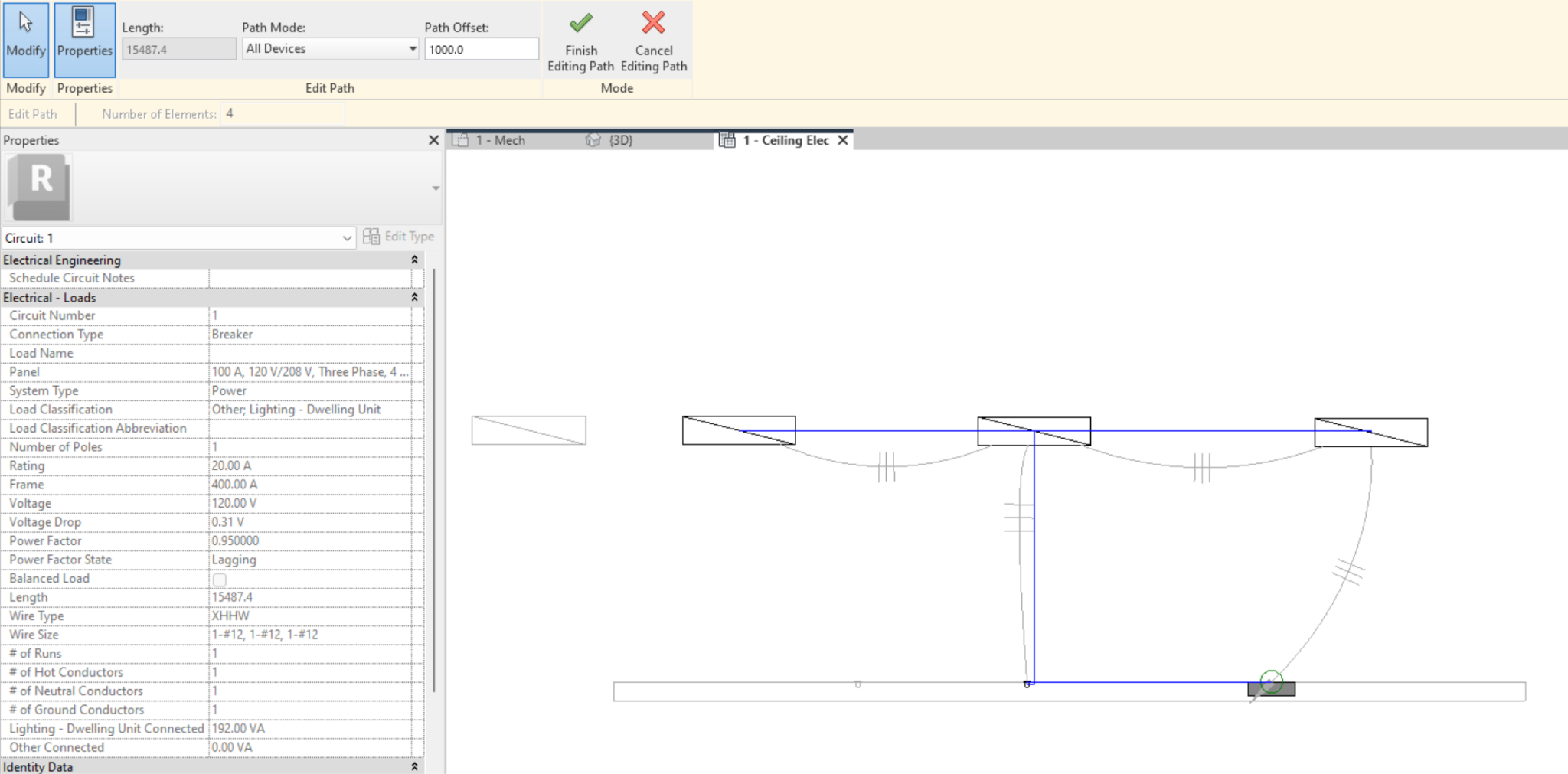
- All Devices: shows the path that connects all devices in the circuit.
- Custom: this mode will appear when we have edited a path and selecting it will display the manually modified path.
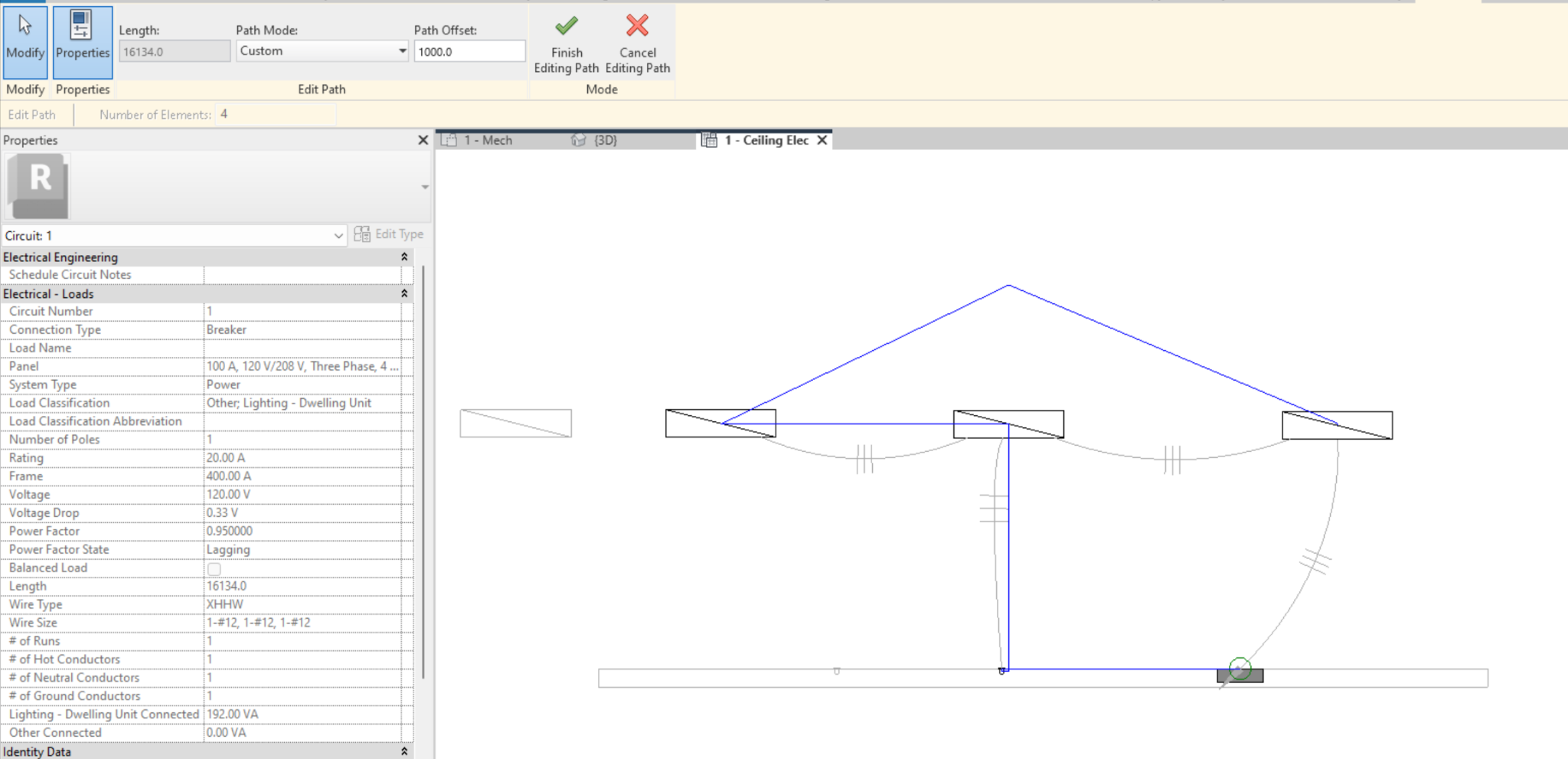
- Path Offset: allows us to set the height of the path, so that Revit accounts for this wire length when bridging the difference in elevation. Entering a value modifies the offset of the entire path. To modify the offset of only one segment you must first select it and then enter a value. A green circle will appear at the vertices between segments with different offset.
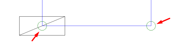
It is important to know that this path is not associated with any modelled instance or category in the model.
- Wire length: We can see the total length of the wire: it appears in "edit path", or in the properties when selecting the electrical circuit, in the "length" parameter.
Wire Properties
As with the circuit properties, we can see the properties of the wiring if we activate "properties" when we go to "Edit Path". Modify / Electrical Circuit → Edit Path → Properties.

However, if we have the properties panel active, we can view the wire properties without the need to access "Edit Path".
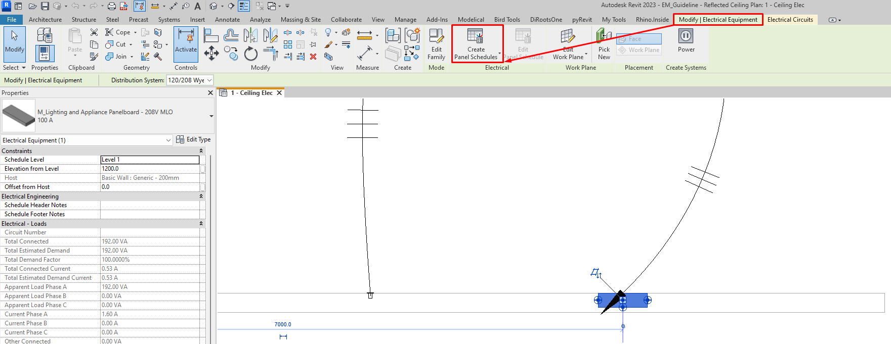
Panel Properties
In the instance properties of a panel, information about the electrical configuration of the panel is displayed.
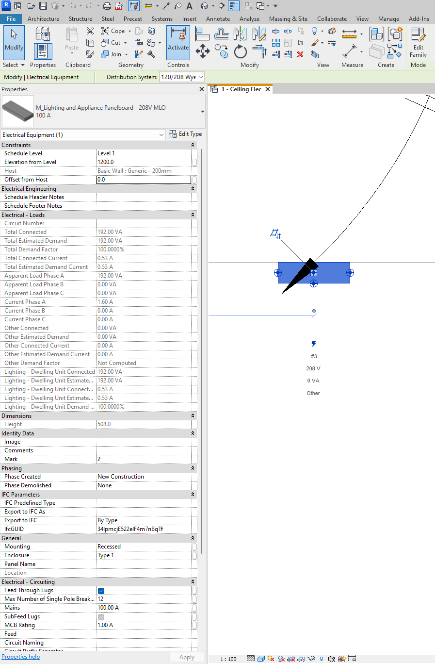
The most important properties are:
- Schedule Header Notes and Schedule Footer Notes: Here we can specify the static text to add to the Header and Footer Notes of the panel, which will appear on Panel Schedules.
- Max Number of Single Pole Breakers: The number of single pole breakers for the panel.
- MCB Rating: The trip rating of the main circuit breaker in a panel.
- We can modify how circuit tags will appear:
- Circuit Naming : Determines the format for the Circuit Number parameter that appears for circuit properties and identifies the circuit in the System Browser. We find 5 options: Prefixed, Standard, Panel Name, By Phase and By Project.
- Circuit Prefix: The text string used as the prefix when Prefixed is selected for Circuit Naming.
- Circuit Prefix Separator: The character or string that separates the prefix from the circuit number.
5. Control and Documentation
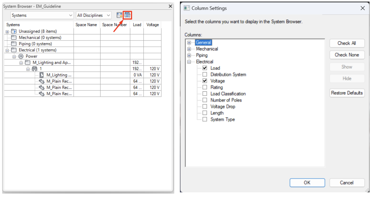
System Browser
The System Browser is a useful tool to check which components belong or do not belong to a system, be it electrical or any other MEP discipline.
To access the System Browser you have to activate it in: View → User Interface → System Browser. It can also be activated with the keyboard shortcut "F9".

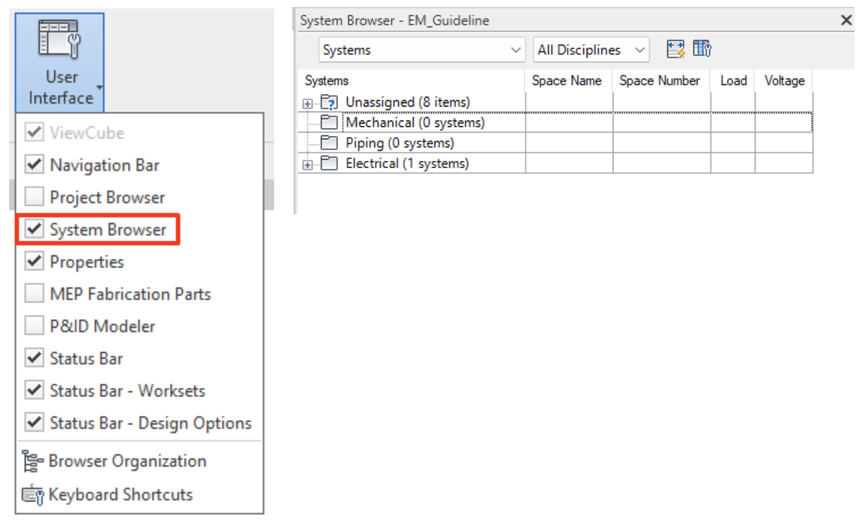
Activating the System Browser opens a separate window displaying a list of all the elements that may belong to a system in each discipline of the project (mechanical, plumbing and electrical), organised by systems, spaces or analytical systems. This window can be docked on one side of the graphic window, just like the properties window.
We can check which elements of the model are not assigned to a system and check which elements make up an electrical system with a hierarchical drop-down list.
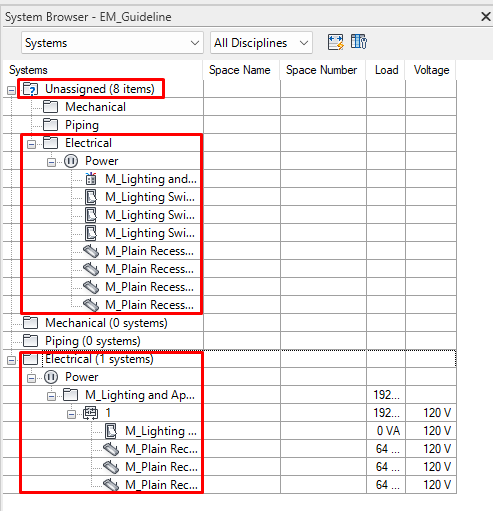
We can also consult data in the same "System Browser", such as the Load and Voltage for each electrical circuit and element. We can modify the information in the columns by accessing "Column Settings" in the upper right corner of the System Browser window.
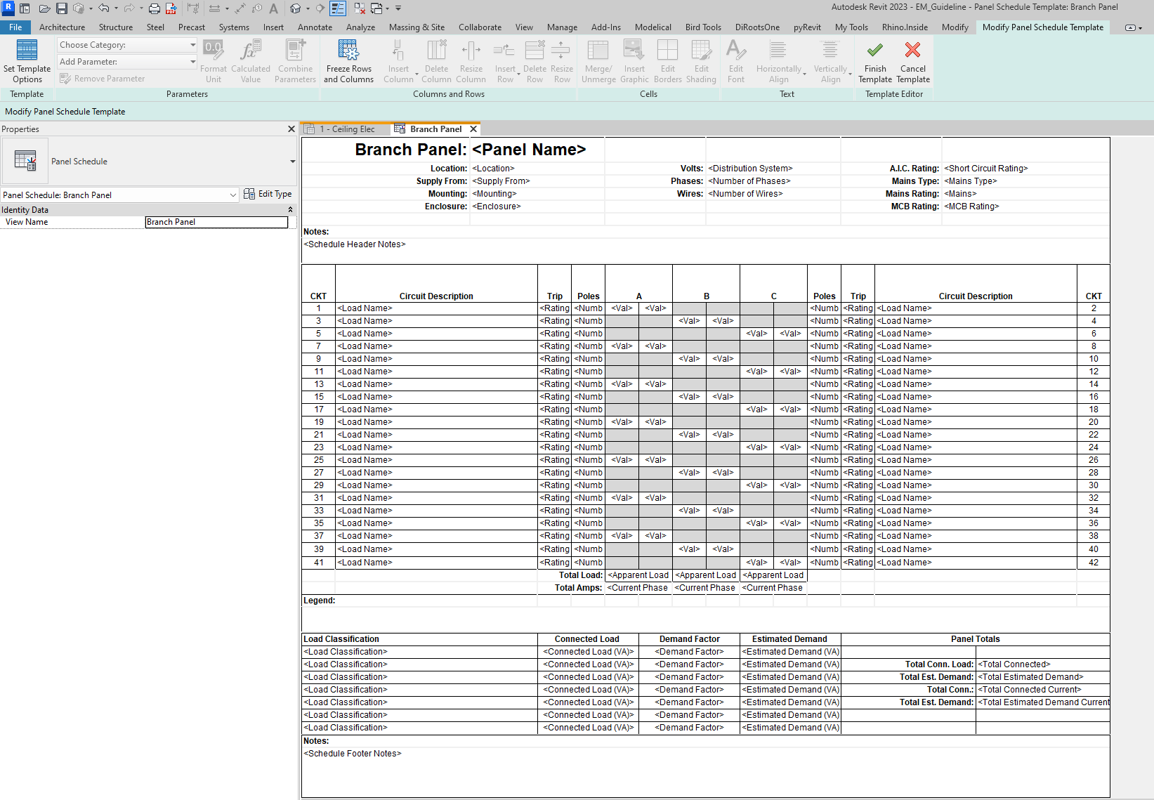
Panel Schedule
Panel Schedules are a special type of schedule that collects information about the panel, circuits and electrical circuit loads. Only one schedule per panel can be created.
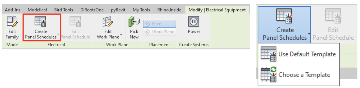
There are two ways to create a panel schedule:
- To create a single panel schedule, if we select a panel, the option "Create panel schedule" will appear in: Modify/Electrical Panels → Electricity → Create panel schedule.
Here you will be given the option to create a default schedule or to select a template.
- To create multiple panel schedules, go to: Analyze → Reports&Schedules → Panel Schedules.

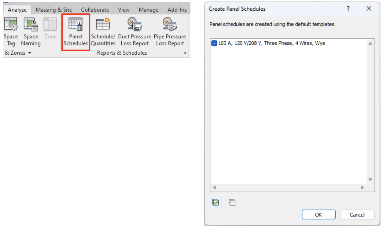
All the panels of the project will appear on the dialog and we can select one or several for which we want to create the schedule. This is generated with a default template, which we can modify later.
A schedule is divided into four parts:
- Header
- Circuit Table
- Loads Summary
- Footer
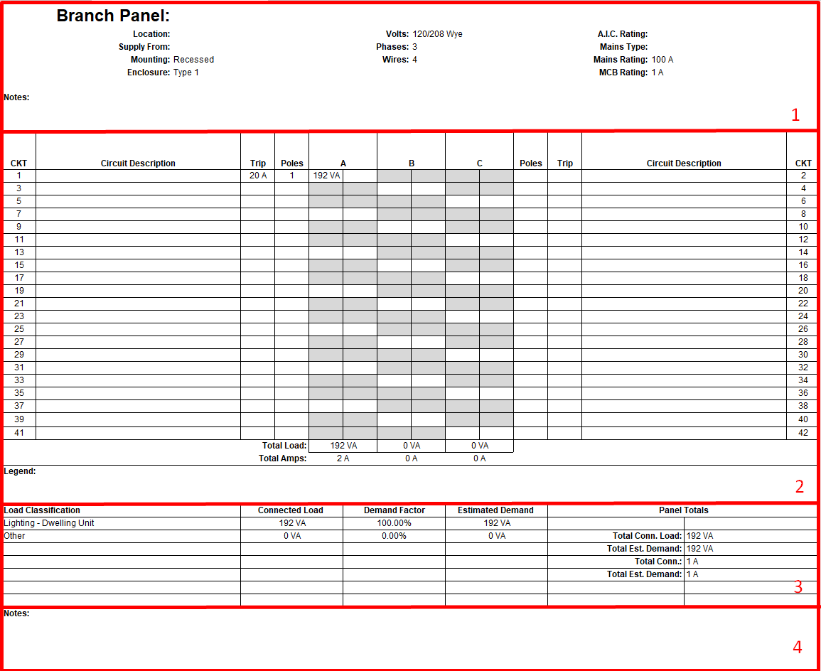
The sections "circuit table" and "loads summary" are automatically filled in with the information of the parameters of the table, while the header and footer must be filled in manually with the information according to the project.
The circuit table and loads summary can be modified through the editing of the template.
Like any other schedule, it’s a type of view, so we can simply drag it onto a plan.
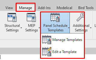
Templates
To create or edit the panel schedule templates, go to: Manage → Settings → Panel Schedule Templates.
Here you can: manage templates or edit a template.

Manage Templates
When accessing Manage Panel Schedule Templates, a window appears from which we can copy, rename and access the edit mode of the schedule templates.
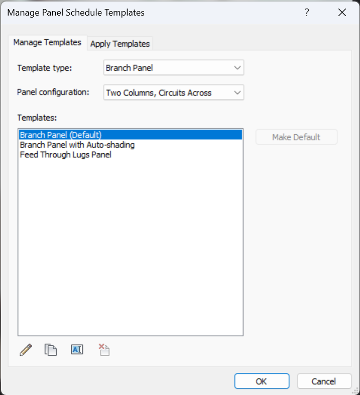
In Template Type Revit offers three types depending on the associated element:
- Branch Panel: can be associated with a control panel device to which a "Power" system is assigned.
- Data Panel: can be associated with a data panel device, mainly associated with telephones, fire alarms and security devices.
- Switchboard: can be associated to a switchboard.
In Panel configuration we can choose the style of the panel schedule for the layout of the data. For the branch panel template type, we can choose between: two columns, circuits across; two columns, circuits down and one column.
However, for data panel and switchboard template types, only the one column option is available.
Finally, under Apply Templates we can assign a specific template to the planning templates of our choice.
Edit a Template
When accessing, a window appears from which you can choose the templates you want to edit:
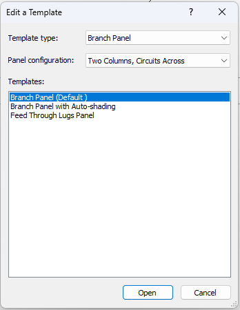
And once opened we access the Modify Panel Schedule Template interface.
Here we can edit, delete or add all project parameters related to electrical circuits. We can also set the format for our panel schedule.
Conclusion
The world of electricity in Revit remains a mystery to most of its users, even to those specialised in installations. Modelling an electrical installation in Revit not only involves knowledge in modelling point and linear families, but also specific knowledge of how an electrical installation works, what the proper configuration of an electrical panel is and what the limitations of the software in its use are.
For this reason we have decided to create a guideline that can touch upon all these aspects, offering a global help for all implications of this discipline for any user who is faced with the modelling, management and/or documentation of electrical installations.
In Revit, we can model an electrical installation in more or less detail, and this will depend on the requirements of each project:
- On the one hand, if the model is to be used for the calculation and control of wiring, panels, circuits and electrical elements, the previous configuration and control of the values must be meticulous, so that the results are adequate and the results can be documented correctly.
- On the other hand, if the purpose of the model is not to calculate the installation or create systems, but to have a volumetric representation and quantification of the elements, we can make a simplified model in which the electrical configuration is not so important.
Tips&Trick
- It is advisable to configure Revit’s electrical settings once and then generate an electrical project template. This is useful so as to not redo previous work in future projects.
- It is important to be orderly in modelling an electrical system. Modelling from the main (larger) elements to the end units can help in having a clean global scheme of the installation.
- It is helpful to create adequate working views, to use simultaneously plan, mirrored roof, 3D and section views, with the addition of working filters. This is important to be able to model complex layouts with good control and coordination among disciplines.
- It may be useful to use "design options" to model different electrical sub-disciplines. It is useful for complex modelling, for example in projects where the requirement is to model a large number of conduits, as it prevents us from having to coordinate between them, preventing them from automatically connecting to each other.
- Using "drafting views" to add single-line diagrams. Revit does not yet have the option of calculating and creating a single-line diagram, so we can import it from a CAD file or create it from scratch in a drafting view.
- We can associate several switch systems to a lighting fixture: As explained in section 4.Modelling → Switch systems, we can associate as many lighting fixtures as we need to a switch system; however, we can only associate a single switch to the system. Thus, we must find alternatives to be able to describe double/triple/poly switching systems. One way is to add a second connector element to the lighting family, which will allow us to connect another system to which we can associate another switch.
Great about conduit modeling. Well why does our contract require 1 1/4″ and not 1″?? Because then it would cost more… We can do a very barebones coordination just catching the largest details very quickly and very cheaply. Or we can dive into ever single detail and create a perfect work of art but it will be slow and very expensive. Or we can do anywhere in between. But once the contract has been set, we are playing the hand we have been dealt.
Thank you for sharing this amazing blog. I am learn a lot from this blog.