Floor creation in Revit
Floor creation in Revit
Notes
This guide is based on the existing functionalities of Revit version 2023.
Objectives
- Learn what floors are in Revit.
- Learn how to create a new architectural or structural floor, understanding all its properties.
- Learn best practices in floor modelling.
Prerequisites
- User knows how to use Revit.
- User has basic notions of Revit modelling and understands the language used.
Index
Introduction
Configuration
- Before starting modelling
- Create a new type of floor
Floor modelling
- Floor: Architectural
- Floor: Structural
- Floor by face
- Floor: Slab Edge
Floor modification
- Sloped Floor
- Floor with variable thickness
- Floor openings
Documentation
- Schedule
- Nomenclature Standards
Conclusion
Tips & Tricks
Introduction
Floors are basic elements of the building model and therefore belong to the Revit system families category.
System families are model elements integrated in the software. They include model components such as walls, floors, ceilings and stairs, as well as other types of elements such as levels, grids and viewports. The general behaviour of these elements is determined by the system and cannot be manipulated. They usually have a large amount of parametric information that is predefined in Revit by default and can be manipulated by creating different types or instances.
These elements are also known as "host" elements as they can receive, support or provide a structure for other model elements. For example, a sump often requires a floor as its host to be placed.
Configuration
Before starting modelling
Before starting to model the floors in the model, and in general any architectural element such as walls or structural columns, it is recommended to have previously generated the "Datum" of the project (levels, grids, reference planes, etc.). This will provide us the necessary references to correctly define the geometry of our floors.
For further information on this, please see our guideline on Datum.
Create a new type of floor
In Revit, creating a new floor (instance) is not the same as creating a new floor type. When a new floor is created, we choose from the existing floor types and model a new instance of that floor type. However, when a new floor type is created, what we do is increase the list of existing floor types in our model.
When creating a new floor type, an existing floor type must be duplicated. A Revit file will always contain at least one floor type, as it is not allowed to delete the last existing type. When creating the new floor, the new floor name must be specified, taking into consideration that two floors can’t have the same name. If a new name is not specified, Revit will assign a default name from the name of the duplicated floor and a " 2" will be added at the end of it.
Duplication can be done in two ways:
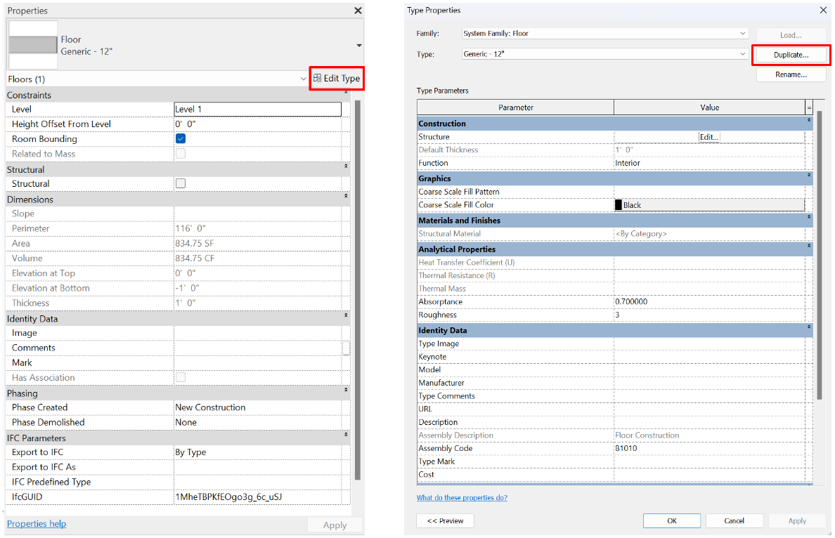
1. Selecting the Floor tool (Architecture Tab> Floors> Architectural Floor) and clicking on Edit Type under the floor selector in the properties panel and then clicking on Duplicate.
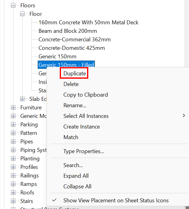
2. The second option is to display the floor family in the project browser, right click on an existing floor type and duplicate it. When duplicating the type, Revit prompts us to change the name and then its properties can be modified in Type Properties.
Type properties
To modify type parameters, we must access them through the Edit Type button in the properties panel. Modifying one of these properties will automatically update all elements with the same type. All type property groups for floors are listed below:
Construction
The first group of parameters includes:
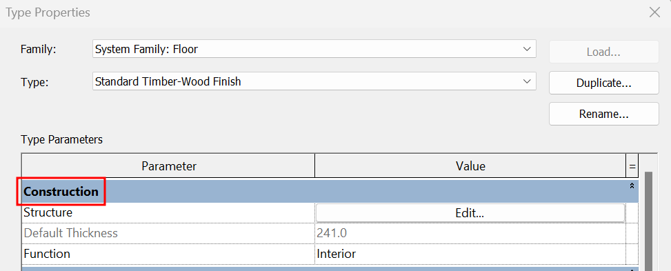
- Default Thickness
This is a non-editable parameter as it is determined by the thickness of the layers combined defined in the Structure parameter.
- Function
It can be an inner or outer type. This property can be used as a sorting method in schedules and for the creation of filters. If the floor needs to be exported for energy analysis it should be looked at into more detail as this function conditions its behaviour in the analysis.
- Structure
This is the most important of all the parameters that define a floor type as it indicates the composition of the floor through its different layers. We can create floors with as many layers as we want, depending on the needs of the project.
Clicking on "Edit..." opens a window from which it is possible to add, remove and reorganise all layers.
The "Edit Assembly" pop-up window is composed of three parts, the first part shows some of the general parameters of the floor, Family, Type, Default Thickness, Thermal Resistance and Thermal Mass of the floor.
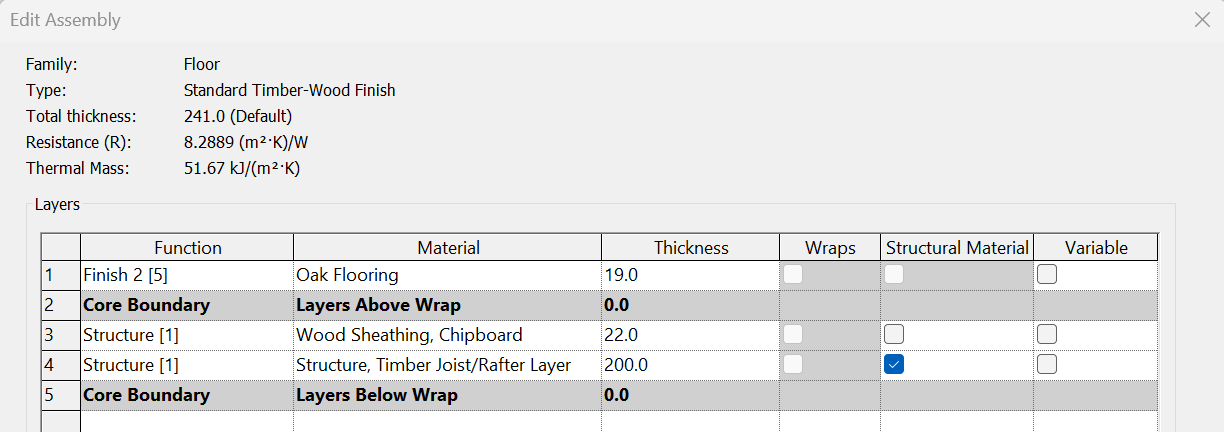
Then we have a table called Layers, from this layer we can edit the floor structure. Each of the rows represents a layer of the floor, so the first layer is always the top layer and we go in descending order down to the bottom layer of the floor. There are a couple of rows called Core Boundary. The layers between these two layers are considered to be the core of the floor, and the layers above or below are the floor coverings or finishes. Only the layers in the core can be configured as Structural Material.
However, in case of doubt, we recommend placing all layers inside the core, as for practical purposes, in a typical architectural modelling, this will not have any effect on the behaviour of the floor.
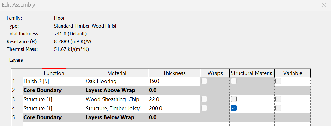
Regarding the columns of the table, we have the following parameters:
- Function Defines the function of the layers: When we create a new layer we must specify the function it provides and at the same time this gives us a level.
- Level 1: Structure [1]
- Level 2: Substrate [2]
- Level 3: Thermal / air layer [3]
- Level 4: Finish [4]
- Level 5: Finish [5]
- Membrane Layer
- Level 1: Structural Deck [1]
The levels refer to the hierarchy that the layer occupies within the building system, in this case the floor.
- Material
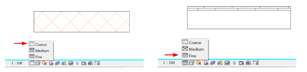
Define layer material: When the level of detail of a view is Medium or High, floor layers will be represented according to the graphical representation of the material. Materials can also be labelled, included in schedule tables and included in material computations.
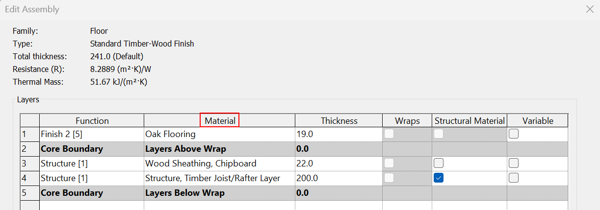
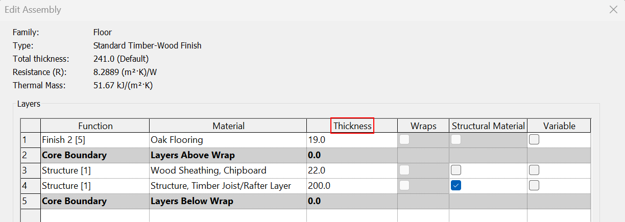
- Thickness
In this column the thickness of the layer must be defined. In case the layer is assigned as a Membrane Layer function, it will have no thickness, which means that Revit requires its thickness to be 0.0.
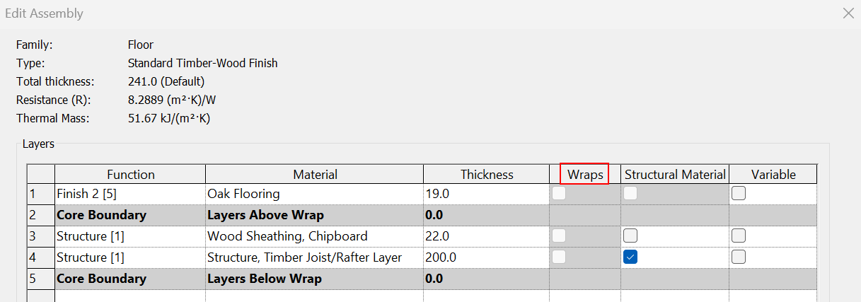
- Wraps
By default this function is not editable as it can only be applied to wall type properties. It does not apply to Floors.
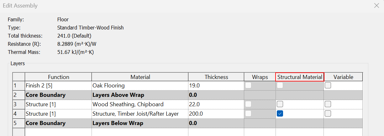
- Structural Material
Define the structural material: By ticking the box, the selected material is added to the Structural Material type property to be used for the structural analysis.
A floor does not necessarily have to have a structural material, and if it does, its function does not necessarily have to be Structure [1], but it is necessary that the material is within the Core Outline.
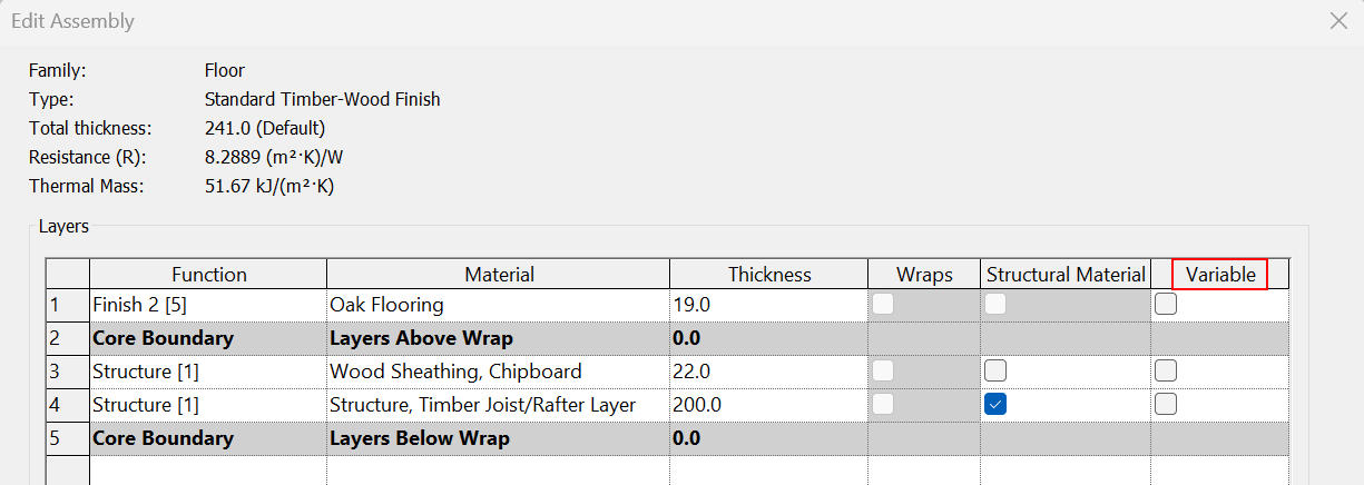
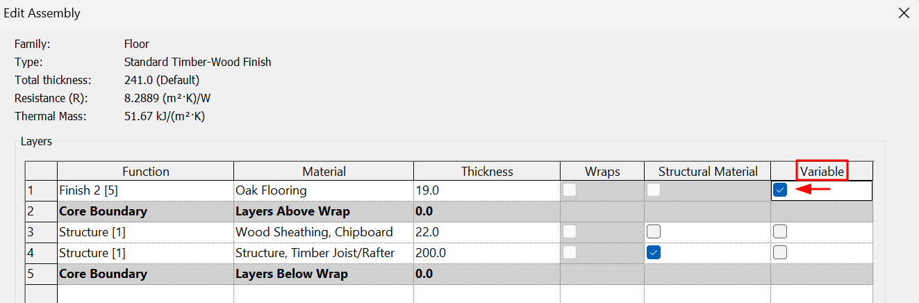
- Variable
Clicking on this option allows you to give a different thickness to the layer using the Modify sub-elements tool. It is especially useful when you want to model the slopes of a floor.
For more details see the section on variable thickness floors in this guideline.
Graphics
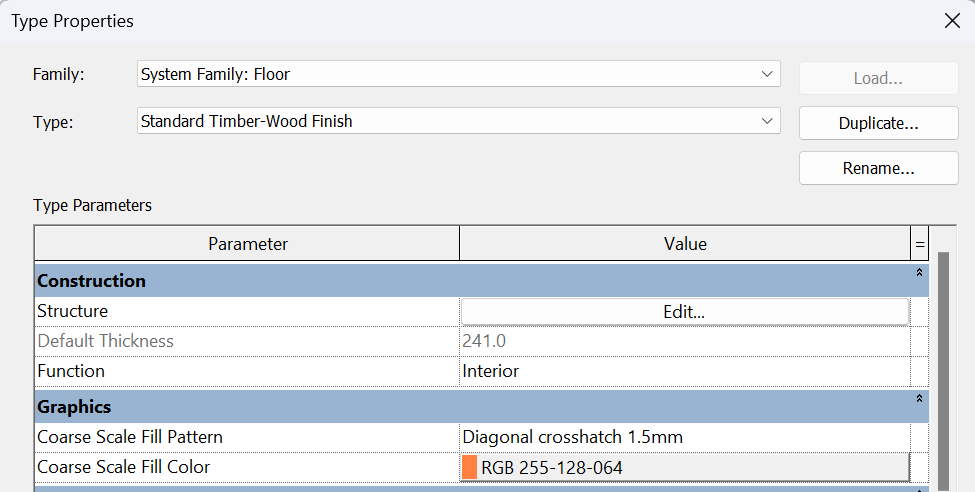
The floor graphics are configured for cases when the floor is cut and set in a low level of detail view:
- Coarse Scale Fill Pattern
Specifies a fill pattern for a low detail view.
- Coarse Scale Fill Color
Applies a colour to the fill pattern for a low detail view.
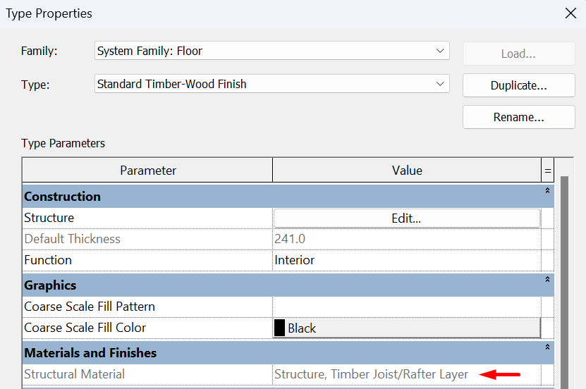
Materials and Finishes
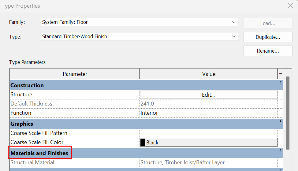
- Structural Material
This is a non-editable parameter, it is automatically filled in if, in the composition of the floor (Structure), a material has been selected as Structural material. If none of the created layers has this option checked, the box will be inactive.
Analytical Properties
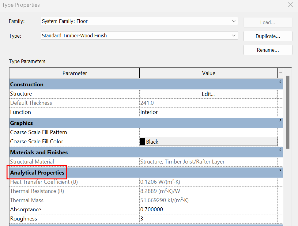
- Heat Transfer Coefficient (U)
It is a non-editable parameter, it is automatically filled in if in the composition of the floor (Structure), a material with this data defined has been selected.
- Thermal Resistance (R)
It is a non-editable parameter, it is automatically filled in if in the composition of the floor (Structure), a material with this data defined has been selected.
- Thermal mass
It is a non-editable parameter, it is automatically filled in if in the composition of the floor (Structure), a material with this data defined has been selected.
- Absorptance
A measure of the ability of a building element to absorb radiation, it is the ratio of the absorbed flux to the incident heat flux. The default value is 0.7.
- Roughness
An index value of 1-6 (where 1 is rough, 6 is smooth and 3 is typical for most building materials) is used to represent the roughness of a surface for the purpose of determining air film strength values in many common thermal calculation and simulation tools. The default value is 3.
Identity Data
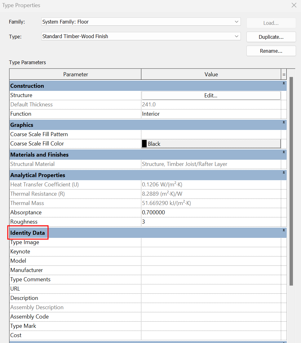
- Type Image
To add an image of the type. These images can then appear in schedule tables.
- Keynote
This is a parameter used for code legends, e.g. numbering of construction details. Keynotes are selected from a text file. They are displayed in tables and can be labelled according to element, material and user. Keynote legends are also available.
For more information, please refer to our Keynotes guideline..
- Manufacturer
It is a parameter intended for floors where a manufacturer may be present. For example, ceramic or parquet flooring.
- Model
Parameter to add the specification provided by the floor manufacturer.
- Type comments
To add an additional comment on the floor type. This comment shall be distinguished from the Comment parameter of each instance.
- URL
If appropriate, a link to a manufacturer's website with the technical specifications of the type of flooring can be included.
- Description
Allows to place a general description of the floor type.
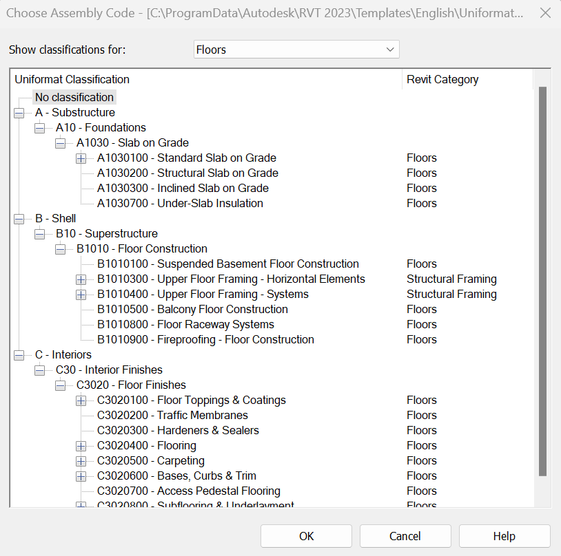
- Assembly Code
It is a parameter based on a classification system. This classification is based on a hierarchical order by levels, based on the elements of a model. Like the keynotes, the assembly code is selected from a text file. It is usually used to add constructive information related to the category of the elements, for example, item code of the element in the budget. They can be assigned to elements, but not to materials.
For more information, please see our guideline on Assembly Codes.
- Assembly Description
Describes the assembler based on a classification system. It is a non-editable parameter, as it depends on the classification selected in the assembly code.
For more information, you can check our guideline on Assembly Codes.
The attached image is the default Revit classification.
- Type Mark
If appropriate, a floor type specific value can be assigned. This value must be unique for each element of a project.
- Cost
If applicable, it can be filled in with the cost of the floor type. This parameter can be included in a specific cost-management software.
Instance Properties
When creating a new floor, its Instance Properties can be modified. These parameters are independent for each element. When we select an element, the instance properties appear in the properties palette. In the following, we will go over the instance properties of the floors one by one:
Constraints
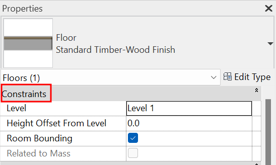
- Level
This is the level on which the floor is placed, it is always aligned with the upper face.
- Height Offset From Level
It is an offset that can be added to change the height at which the floor is placed regarding its reference level.
- Room Bounding
Indicates whether the floor will behave as a room boundary element. When creating a floor, this option is set by default and is normally left as is.
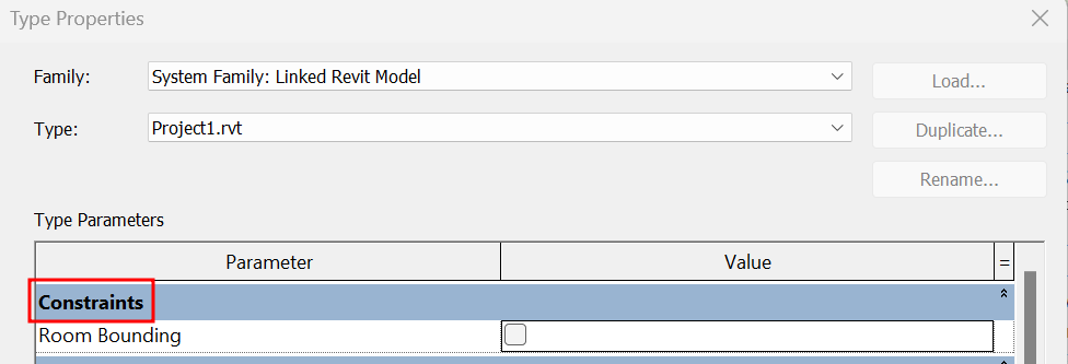
With linked models, no element (walls, floors or roofs) will be room bounding unless the Room Bounding option is clicked in the type properties of each link.
- Related to Mass
Indicates that the element was created from a mass. This is a read-only value. The floor is not removed if we remove the mass, only the parameter box appears without the click, indicating that the floor does not have a mass related to it.
Structural
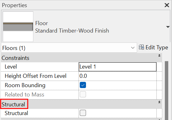
- Structural
If this option is not selected, the rest of the structural options are disabled. In the views whose discipline is Structure, only the walls with this option selected will appear.
- Enable Analytical model
Allows the structural analysis of the floor.
For more information on the configuration of the analytical model, you can check our Structures guideline.
Dimensions
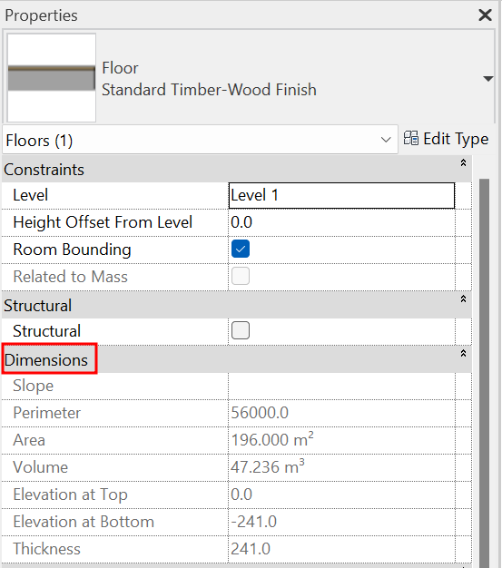
- Slope
This parameter is populated by ticking the Define slope to one or more lines of the floor sketch. If no slope is defined, the parameter appears as inactive.
- Perimeter
It calculates and reports the perimeter of the floor, so this is a read-only value.
- Area
It calculates and reports the floor area, so this is a read-only value.
- Volume
It calculates and reports the volume of the floor, so this is a read-only value.
- Elevation at Top
Indicates the elevation used to mark the top of the floor. This is a read-only parameter that informs. Varies for sloping planes.
- Elevation at Bottom
Indicates the elevation used to mark the bottom of the floor. This is a read-only parameter that informs. Varies for sloping planes.
- Thickness
Indicates the totall thickness of the floor. If the floor structure does not contain any layers marked as Variable, this value is read-only. If one or more layers are marked as Variable, this parameter can be edited. By modifying the Thickness parameter, the layer defined as Variable shall be modified to fit the value indicated in the parameter.
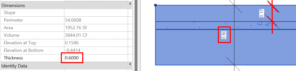
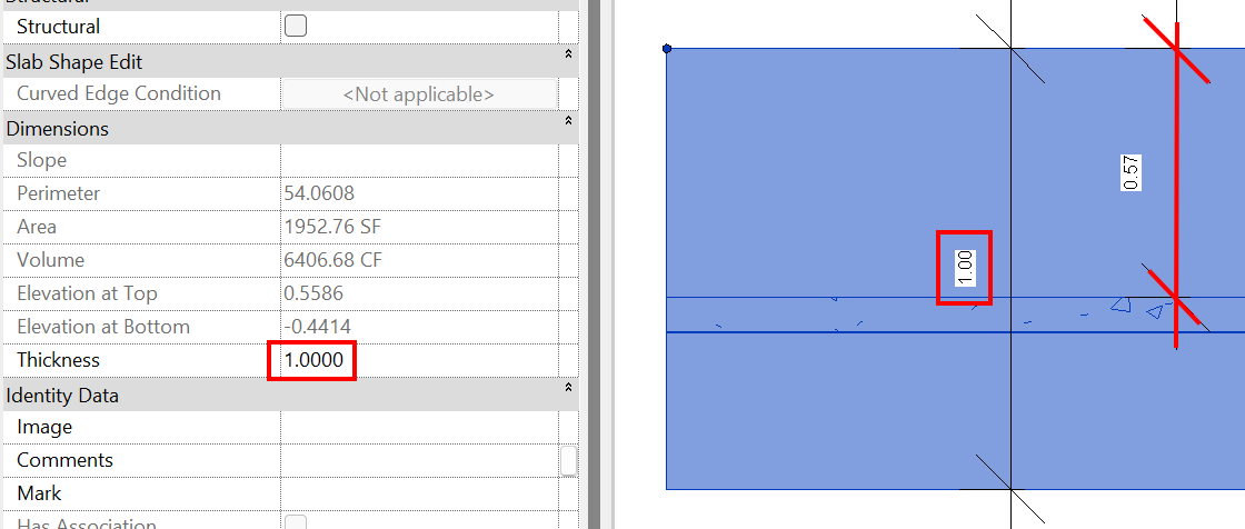
If the sub-elements of the layer are modified, there is a variation in the thickness of the floor, so the Thickness parameter will not contain any value.
Sub-elements are a tool that allows you to manipulate one or more points or edges of a selected element.
For more information, see the section on Floors with variable thickness.
Identity Data
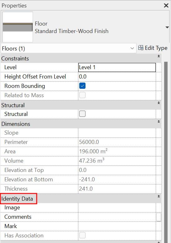
- Image
To add a unique image of the element. These images can then appear in schedules.
- Comments
Add an additional single comment for each floor element.
- Mark
Add an instance mark for each element of the floor. This value must be unique for each element. If two elements have the same mark, a warning will pop up, but it allows us to continue using it.
Phasing
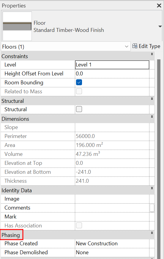
- Phase Created
The phase in which the floor was created.
- Phase Demolished
The phase in which the floor is demolished (only if applicable).
For more information on phasing, please refer to our phasing guideline..
Slab Edge
Slab edges are system families used to modify the geometry of floor edges, for example when the slab has an undercut or an overhang.
Within Revit they are a subcategory of the floor system.
Type properties
When creating a new slab edge you can modify its Type Properties. All type property groups are listed below:
Construction
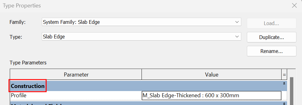
- Profile
A predefined profile must be selected in the project or a new one must be created to specify the slab edge profile to be extruded according to the edge line to which it is associated.
Materials and Finishes
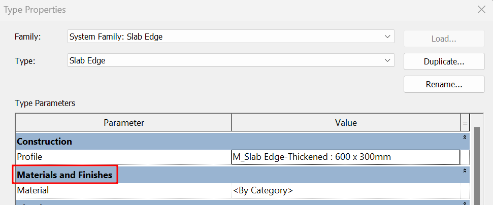
- Material:
Slab edge material can be defined to control the appearance of the slab.
Identity Data
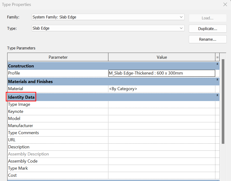
The Slab Edge Identity Data parameter sets are the same as those that apply to floors. Check the Floor Type Properties section for a description of each floor.
Instance properties
In the following, the instance properties of the slab edges are described one by one:
Constraints
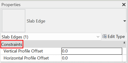
- Vertical Profile Offset
It is an offset that can be added to modify the height location of the profile.
- Horizontal Profile Offset
This is an offset that can be added to modify the horizontal location of the profile.
Dimensions
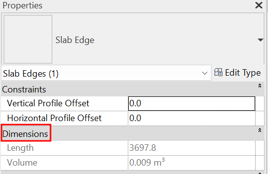
- Length
It calculates and reports the length of the edge, so this is a read-only value.
- Volume
It calculates and reports the volume of the slab edge, so this is a read-only value.
Identity Data
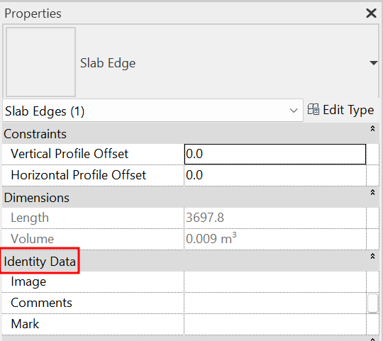
- Image
To add a unique image of the element. These images can then appear in schedules.
- Comments
Add an additional unique comment for each slab edge element.
- Mark
Add an instance mark for each slab edge element. If two elements have the same mark, a warning will pop up, but allows us to continue using it.
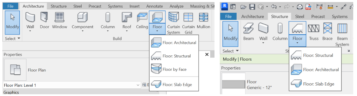
Floor modelling
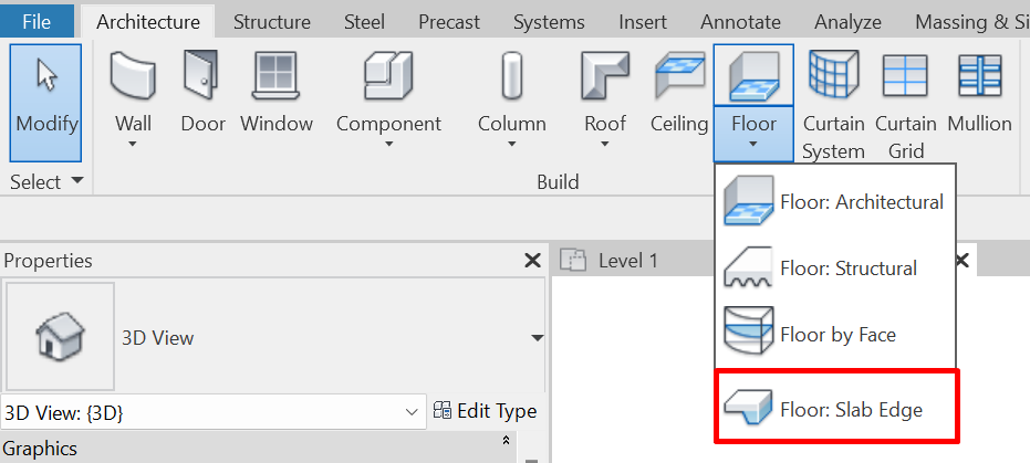
Floors can be created from the Architecture or Structure tabs. Selecting the Floor tool displays the menu with four options for creating floors:
- Floor: Architectural
- Floor: Structural
- Floor by face
- Floor: Slab Edge
Floor: Architectural
This is the default option we will use in most cases to model a floor.
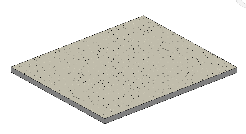
Boundary Line definition
When creating a floor, its boundaries must be defined. This can be done by selecting walls or by drawing a sketch with the drawing tools. Once defined, Revit extrudes it according to the characteristics defined in the Type Parameters. We must keep in mind that the level of the plan view where we are drawing the sketch, and the height offset that we indicate to the floor (by default it will be 0) will define the upper face of the floor.
The opposite happens with roofs, where the reference level and height offset define the position of the lower face and the element is extruded upwards.
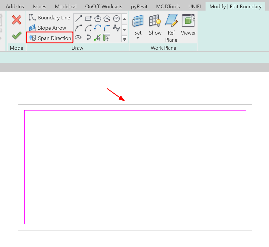
Span Direction
The span direction is used to define the direction of the main lines of the structure, e.g. in which direction the joists in a slab will be placed in a floor slab.
You will see that one of the lines that define the outline of the perimeter has a double line symbol on each side, which indicates the direction of the span. We can modify this direction using span direction, or define it manually, using the Line option.
Slope Arrow
This option allows you to define the slope that the floor will have, therefore, it only applies to sloping floors.
See section about Sloped floors for more information.
Finish Edit Mode
When the floor boundary is finished, click Finish edit mode.
Floor: Structural
The structural floor creating procedure is the same as for architectural floors.
The Structural Floor option ensures that the Structure instance parameter is set by default, which means that some analytical properties are enabled for structural analysis. For example, when a project requires the modelling of the floor structural reinforcement, this option eases the specification of the cover reinforcement on its different faces.
For additional information, check our guideline on reinforcement..
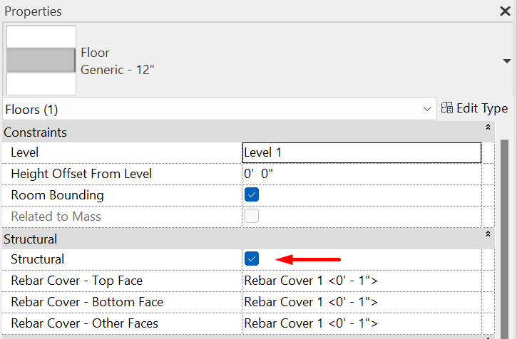
By checking this box an architectural floor becomes a structural floor and vice versa. When a Structural floor is created, the floor automatically creates the span direction symbol.
By unchecking the Structure checkbox, this symbology is not removed, so it must be deleted manually to convert the floor into an architectural one.
Floor by face
The option Floor by Face is used to transform Mass Floors into architectural floors.
Mass creation
The first thing to do is to create a mass in Revit from which we can generate Mass Floors.
Our Masses guideline explains in depth how these Revit elements are generated.
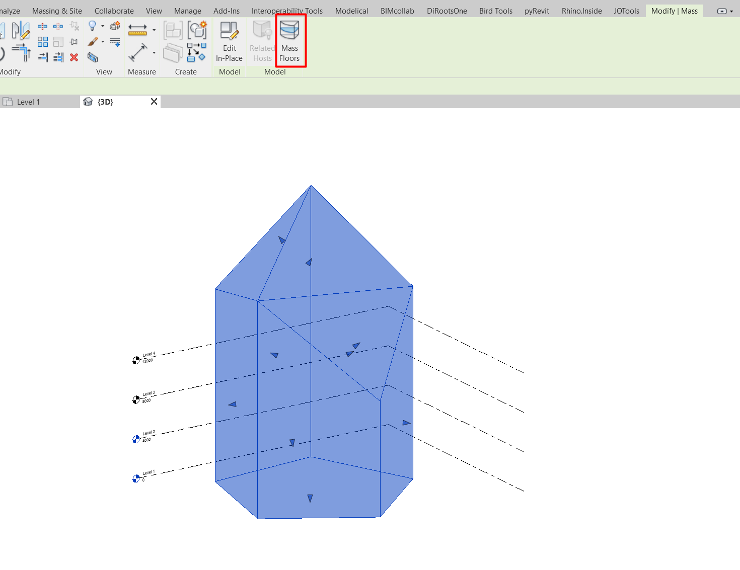
Mass Floors creation
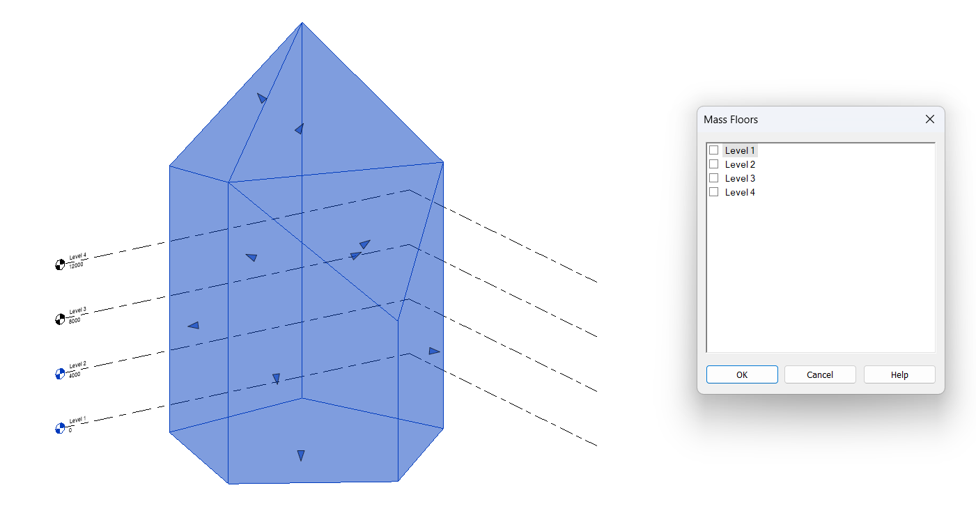
Once the mass has been generated, click on it and click on the option Mass Floors, under the tab Modify > Model.
A pop-up window will open asking us to select in which levels we want to generate our floors.
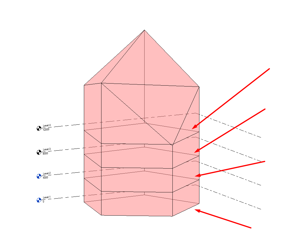
Floor by face creation
Once the Mass Floors have been generated, we can generate the architectural floors. To do this, click on the button Architecture > Floors > Floor by Face and select the Mass Floors in which you want to generate an architectural floor.
Three buttons appear for the generation of this type of floor under Modify > Multiple Selection.
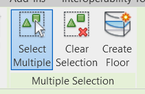
- Select Multiple: while clicked we can select and unselect as many Mass floors as we want in order to generate architectural floors from them.
- Clear Selection: clears the selected selection of mass floors.
- Create Floor: creates a new floor for each Mass Floor we have selected.
Each new floor will have the boundary and level of its host floor.
If we delete the host floor, our created floors will remain in place, unlinked to the original host. In addition, we can modify the boundary, type and level of our floors created by face at any time, just like any other floor.
Floor: Slab Edge
Create a new slab edge
Slab edges can be created either from the Architecture tab or Structure tab. Selecting the Floor tool displays the menu where the Floor: Slab edge option is found.
Once the tool is selected, select the outline of an existing floor in the model, which will be the host for the new generated slab edge.
Once the new slab edge has been generated, we can modify its type and its horizontal and vertical offset.
If we delete the host floor, all related slab edges will be deleted with it.
Floor modification
Once a floor has been created, we may need to modify it, either to give it slopes, or to create floor slab holes in its interior, we are going to see some ways to be able to do this:
Sloped floors
Revit allows us to model floor surfaces with specific slopes or inclinations. Depending on the needs of the project, the slope of the surface can be easily defined in terms of percentage, degrees or by an elevation at the end.
Floor slopes can be generated by one of the following procedures:
Slope arrow
The procedure for creating a sloping floor with a slope arrow is as follows:
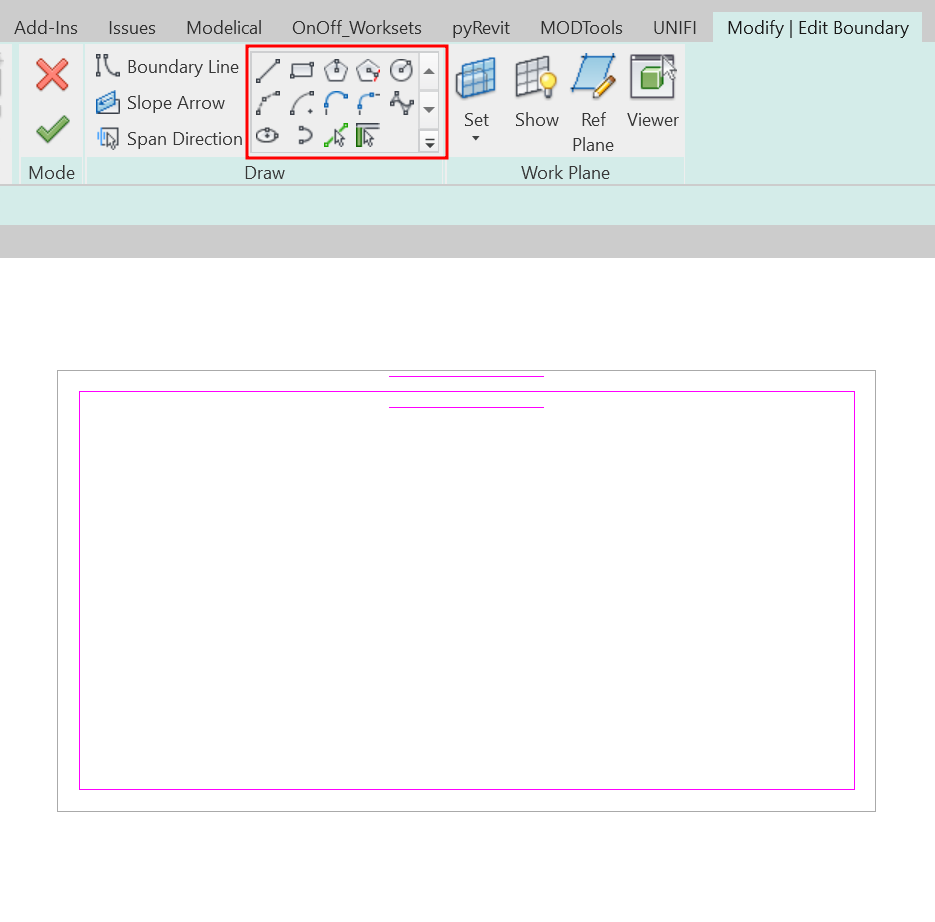
- Select the floor and edit its outline by clicking on the Modify | Edit Boundary tab.
- In the Draw group and select Slope Arrow.
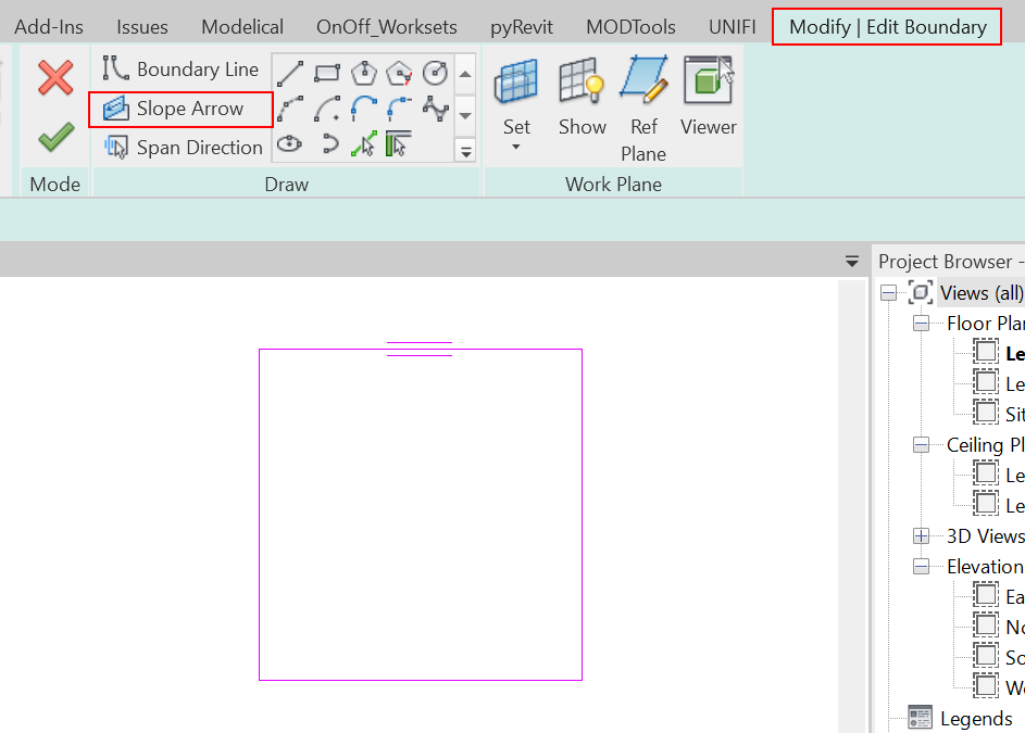
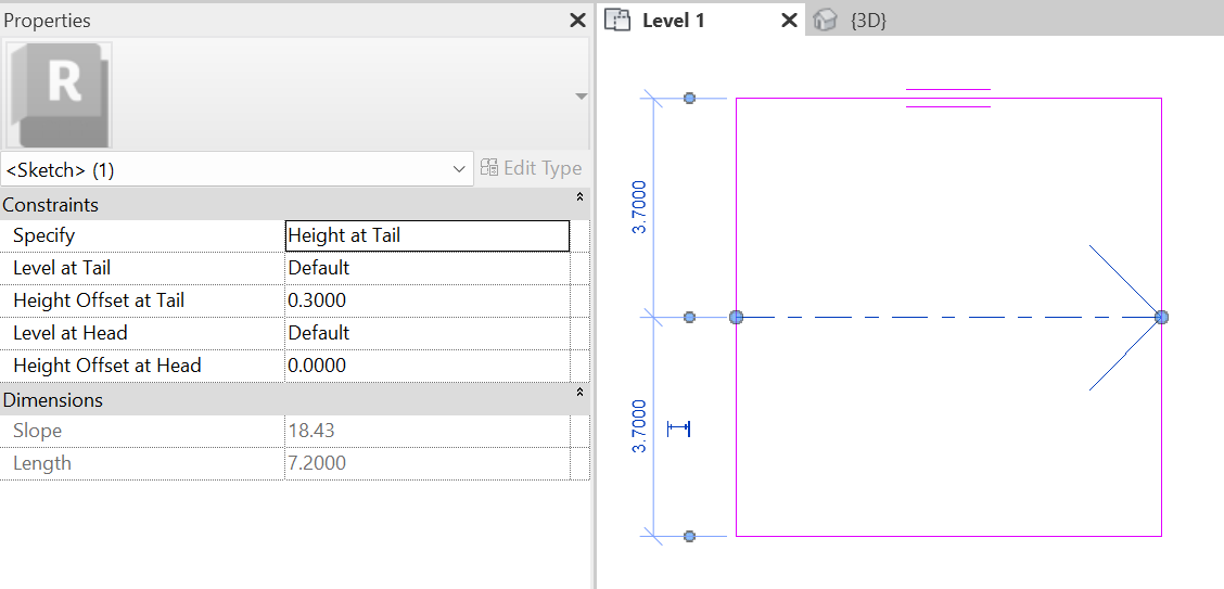
- Draw an arrow in the drawing area. Click once to specify its starting point and click again to specify the end point. When you select the arrow you must specify how you want to create the slope. There are two options:
- Height at Tail: defines the height at the end of the floor. Therefore, the End Height Offset and the Start Height Offset must be specified. The slope is automatically calculated to reach the specified height from the starting point of the floor.
It is important to note that if we make the arrow shorter and do not modify the Height Offset values at Start and End, what we are doing is increasing the slope of the floor.
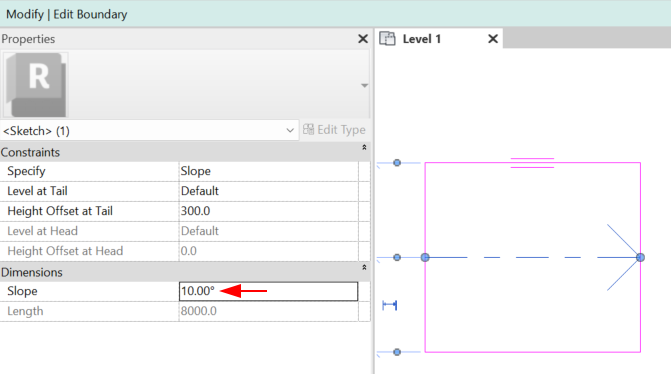
- Slope: directly defines the slope of the floor.
- Click Finish edit mode to finish editing the floor.
Parallel sketch lines
To create a sloping floor using parallel sketch lines the procedure is as follows:
- Select the floor and edit its boundary by clicking on the Modify | Edit boundary tab.
- Select the line you want to change the height of. In the Properties panel click Defines Constant Height and then specify the values for Level and Offset From Base.
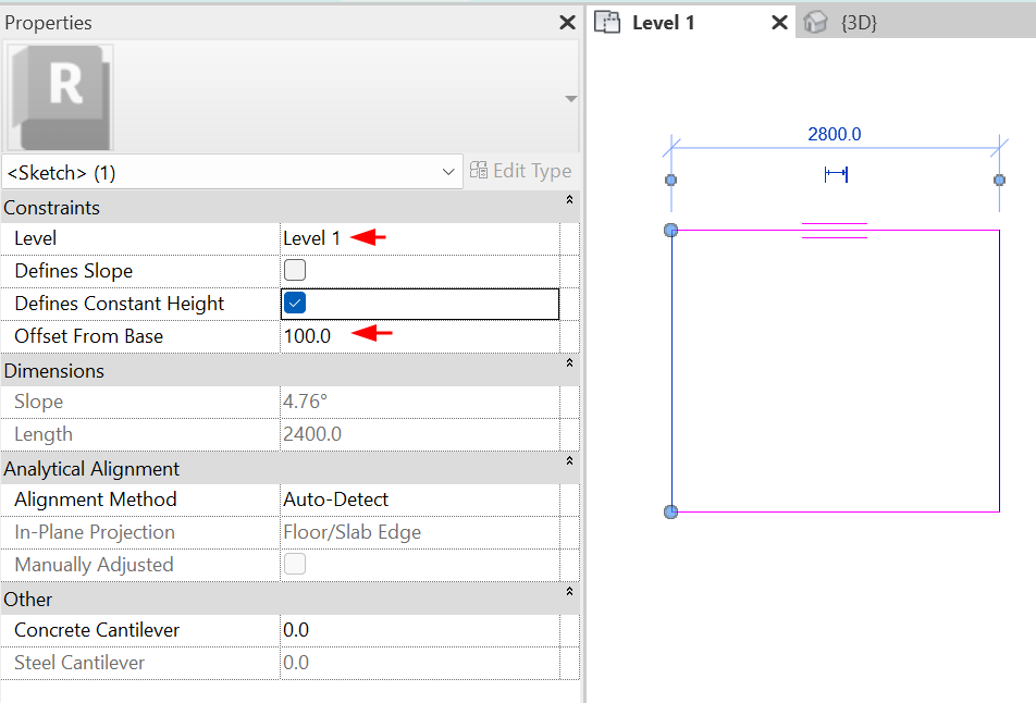
- Select the line parallel to the previously selected line and using the same method, specify the same parameters.
- Click Finish edit mode to finish editing the floor.
Single sketch line
To create a sloped floor using a single sketch line the procedure is as follows:
- select the floor and edit its boundary.
- Select the line that you want to modify its height. In the Properties panel click on Define Constant Height, Define slope and then specify the values for Level and Offset From Base.
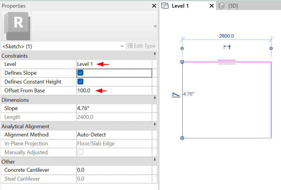
- Click Finish edit mode to finish editing the floor.
Floor modification by Sub elements
This tool allows us to model floor surfaces that do not have a uniform thickness over their entire length, which gives us greater precision in the specific needs of the project. It consists of selecting specific points on the surface of a floor and modifying its height regardingthe height of the floor base.
It is useful for representing architectural floors with deformations such as small ramps, topographical variations of the terrain, pavements, roof skirts, among others.
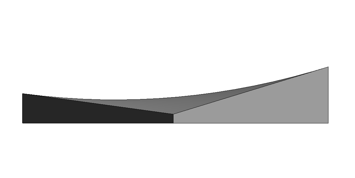
Some preliminary considerations must be taken into account when modifying floors in this way:
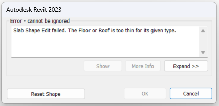
- It can only be applied to flat floors. Trying to give a slope to a sub-element modified floor using any of the above procedures will force us to reset the floor shape with the following error message display.
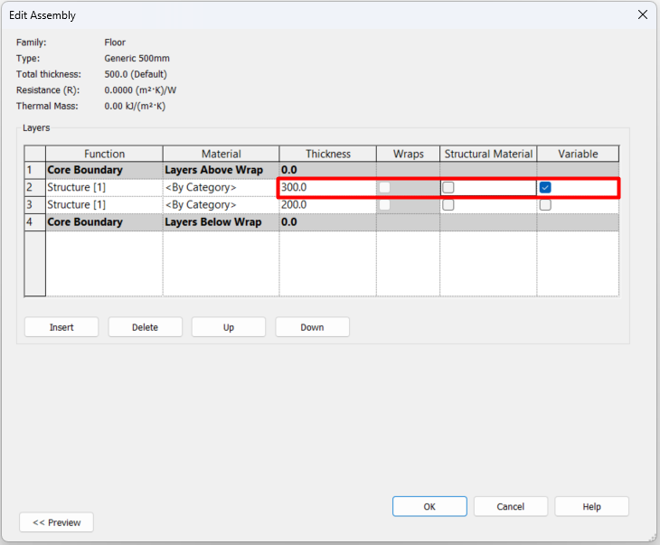
- The possibility of changing the floor thickness is a feature of one of the floor layers. Modify the Floor Type Properties so that the desired layer is Variable and click OK. Only one layer of the floor can be variable.
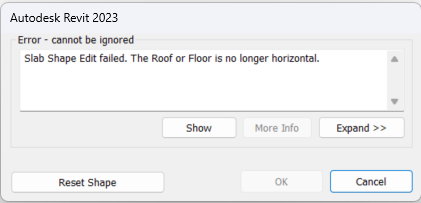
- If we have one of the floor layers set as variable, keep in mind that with that floor sub-elements points it’s not possible to go lower than the the thickness of that layer.
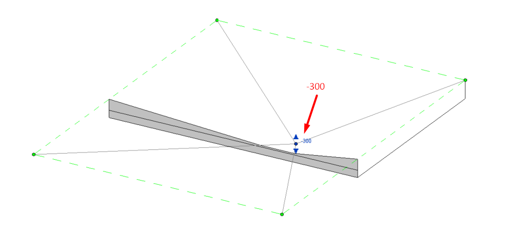
Otherwise, it will force us to reset the shape of the floor, and the following error message will be displayed on the screen.
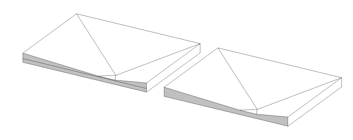
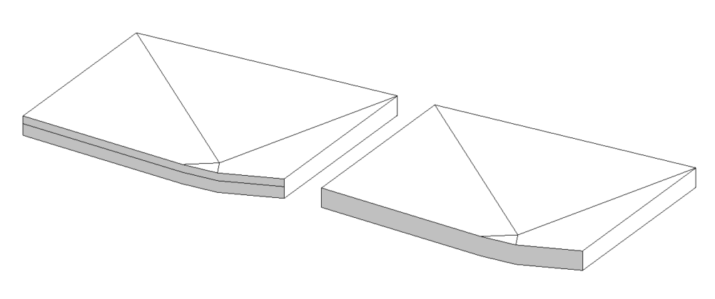
- If none of the floor layers are defined as variable, the given slope will affect the upper and lower faces as the slopes will be replicated on the floor bottom face also, regardless of the number of layers in the floor.
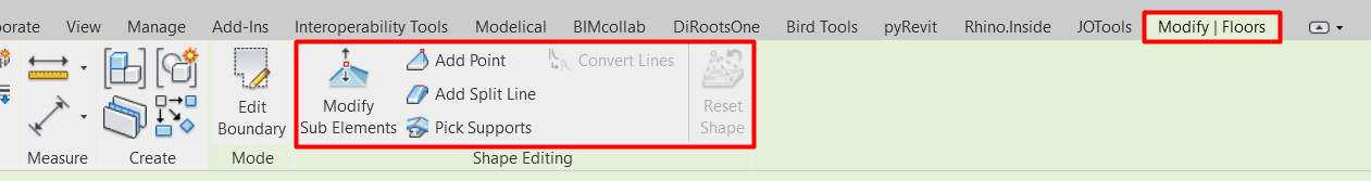
The procedure for changing one or more points on a floor is as follows:
- Select the floor you want to edit.
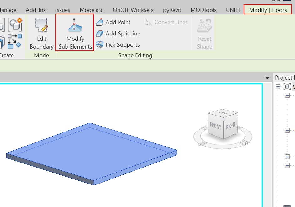
- With the floor selected, click on the Modify | Floors tab then within the Shape Editing group and select Modify Sub Elements.
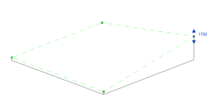
- Select a point on its surface or an edge to change its height.
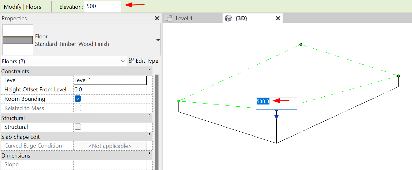
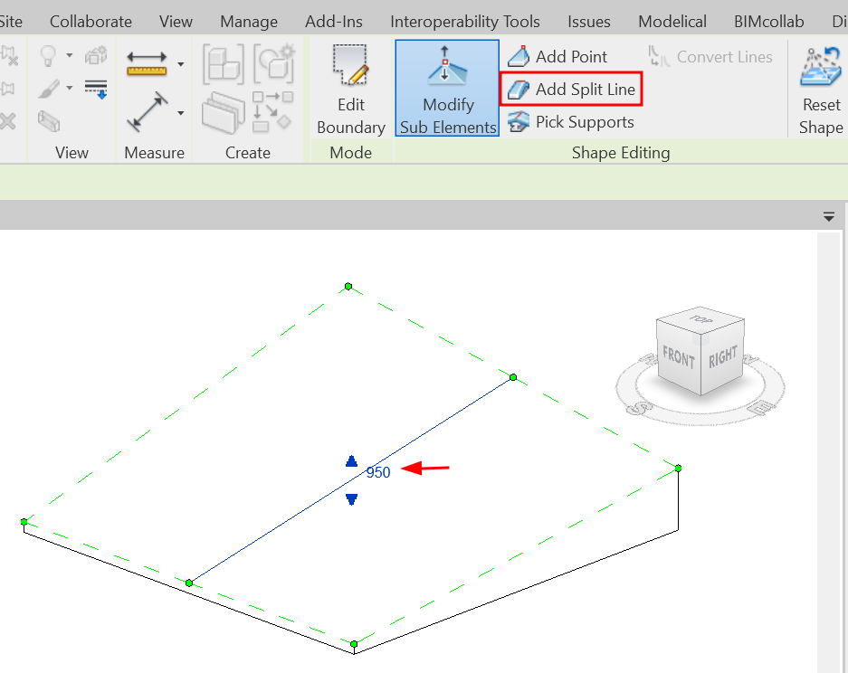
- By selecting an arrow you can give a specific value to that point. To set a value,click on the text control or in the Elevation box. You can also give a value by dragging up and down the blue arrow.
- More points can be edited to create more precise editing.
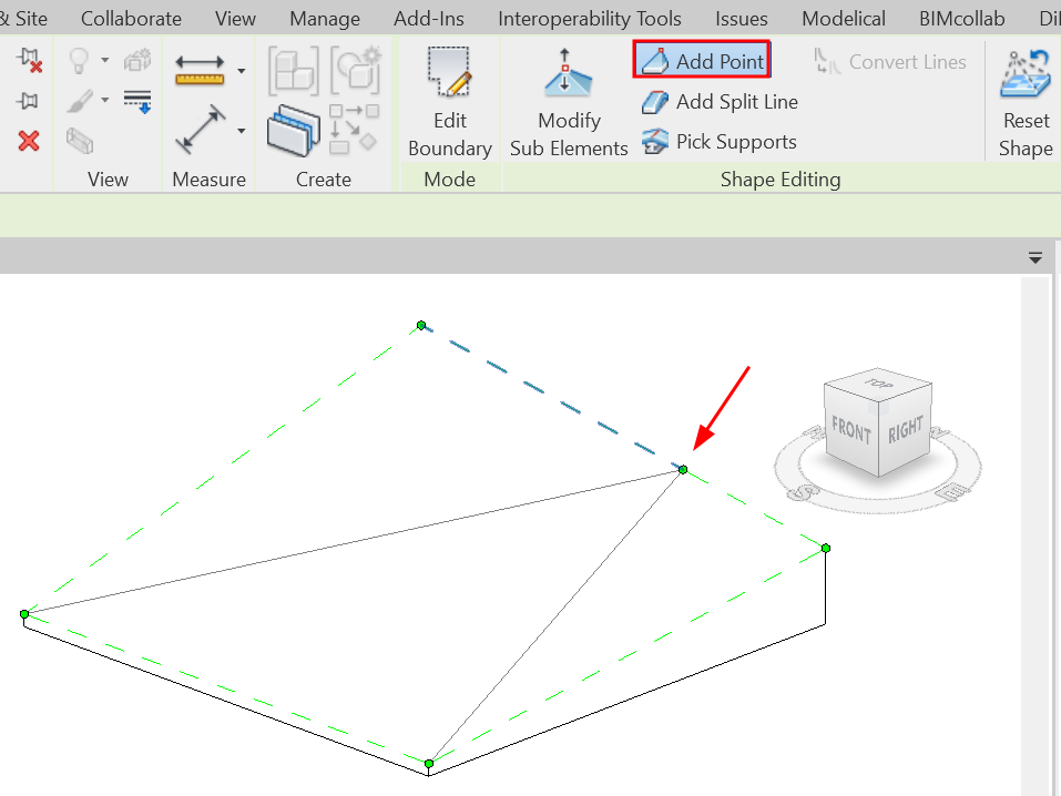
- A split line can be added to divide the floor to create two different slopes.
- When editing the floor by selecting an edge, the centre moves to a specific height, but the relative heights of the edges remain the same.
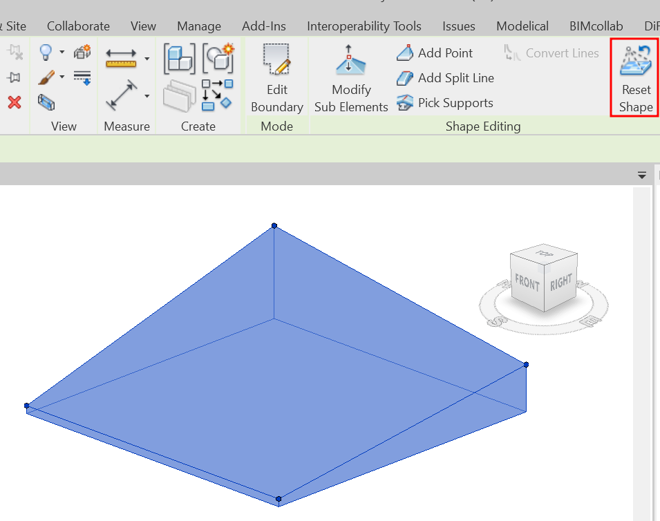
- Press ESC to exit the floor editing mode.
- If needed, click Reset Form to undo the changes.
Floor openings
There are different tools for the creation of openings:
- Opening - By face: allows us to make a hole in a floor or roof perpendicular to the face of the selected floor or roof, the hole is only applied to the selected element.
- Opening - Wall: similar to the previous one but only applied to walls.
- Opening - Vertical: similar to the first, but the hole is always created vertically, no matter the slope of the element to be cut.
- Opening - Dormer: this type of hole is used to generate dormer windows in roofs.
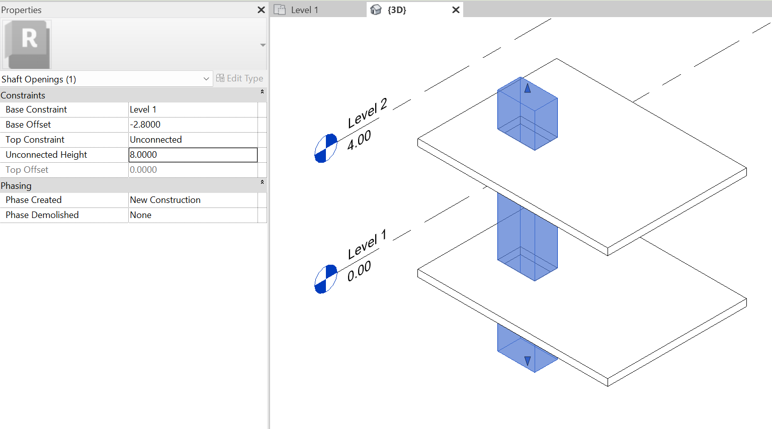
To make openings in floors it is recommended to use the Shaft- Opening tool. This tool generates a volume that can go through several levels, cutting all floors that pass through this void volume. This tool is often used to create holes for letting building facilities pass by or lift shafts, for example. These holes are an independent category and their display and graphic properties can be modified.
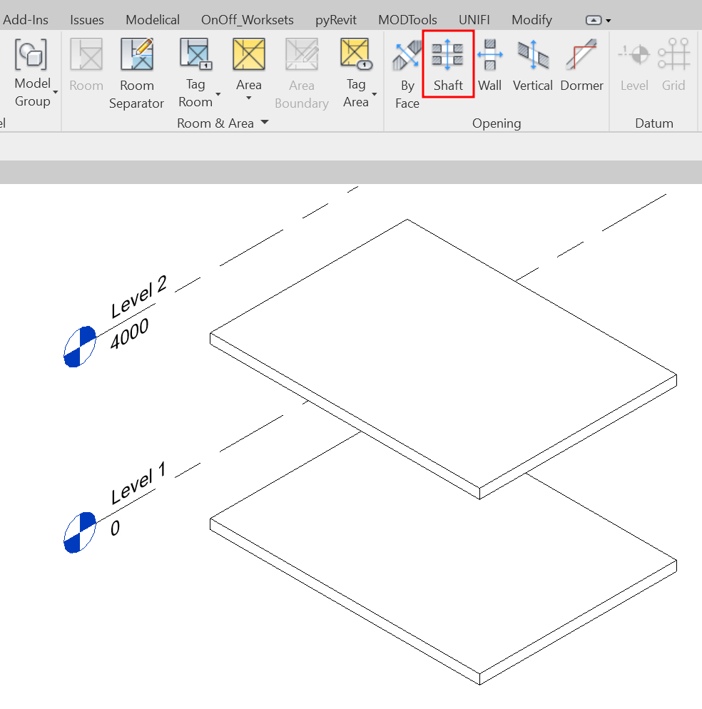
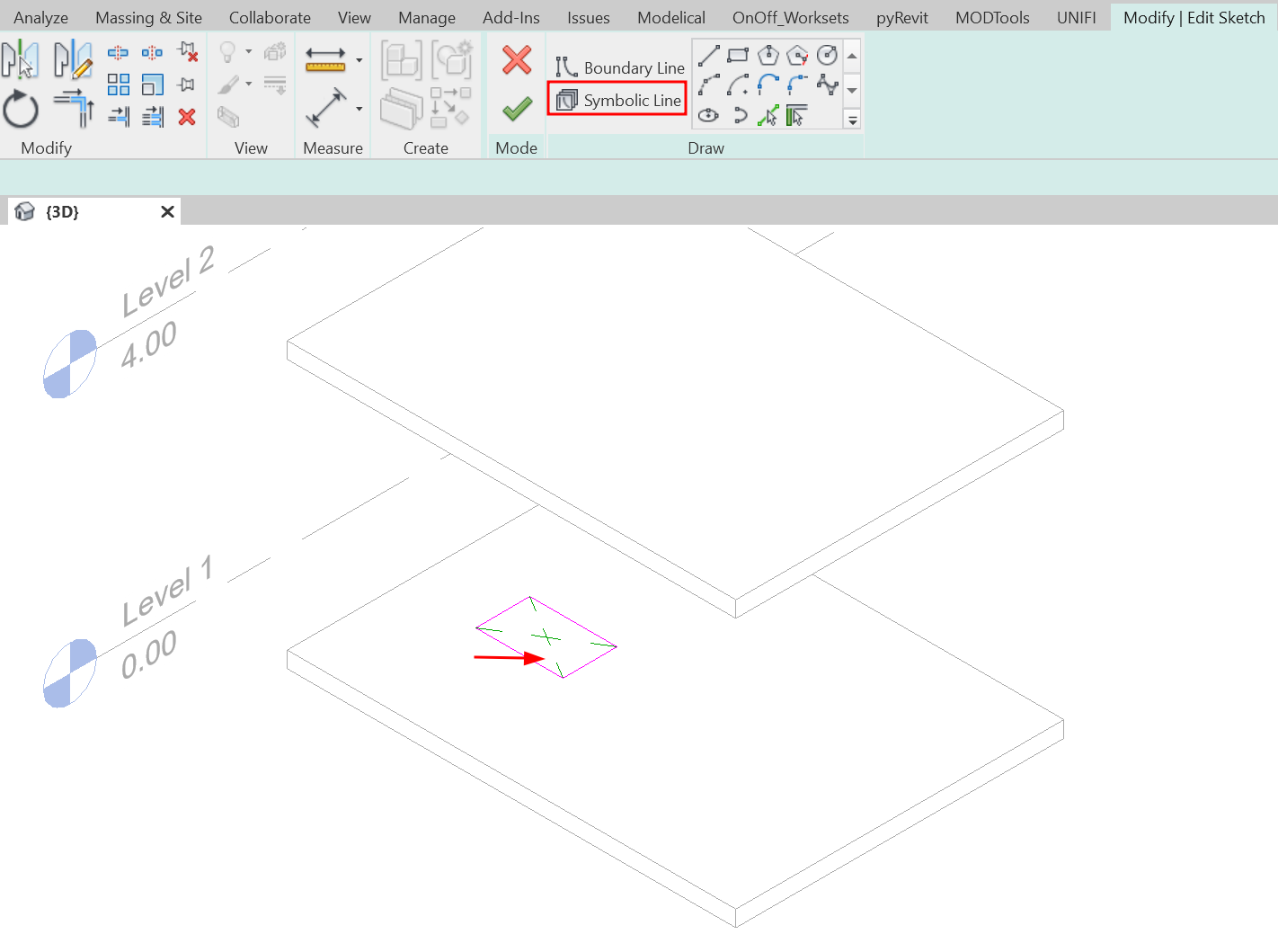
Symbolic lines can be added within the boundary editing to visualise the openings in plan views.
Documentation
Model Schedules
Model Schedules are a very useful tool to be able to correctly manage the floors of our models. It is always convenient to use schedules to control our floors. With alphanumeric data we can quickly control the correct placement of the floors and their characteristics. All changes made in the schedule will be reflected in the model and vice versa.
For more information on planning tables, see our guideline.
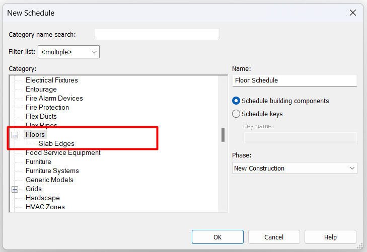
The first thing we notice when we try to create a floor planning schedule in Revit is that we have two options within the floor category: Floors and Slab Edges. This already tells us that we can create specific schedules for each of these Revit categories.
Floor Schedules
A floor schedule is very similar with any other Revit schedule, but it is good that we take into account some of the particularities for this type of family.
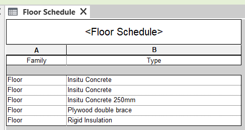
- These are System families, for this reason, it does not make sense to try to filter the results by the 'Family' parameter, as in all cases the result will be the same. We will always try to filter the results directly by the 'Type' parameter.
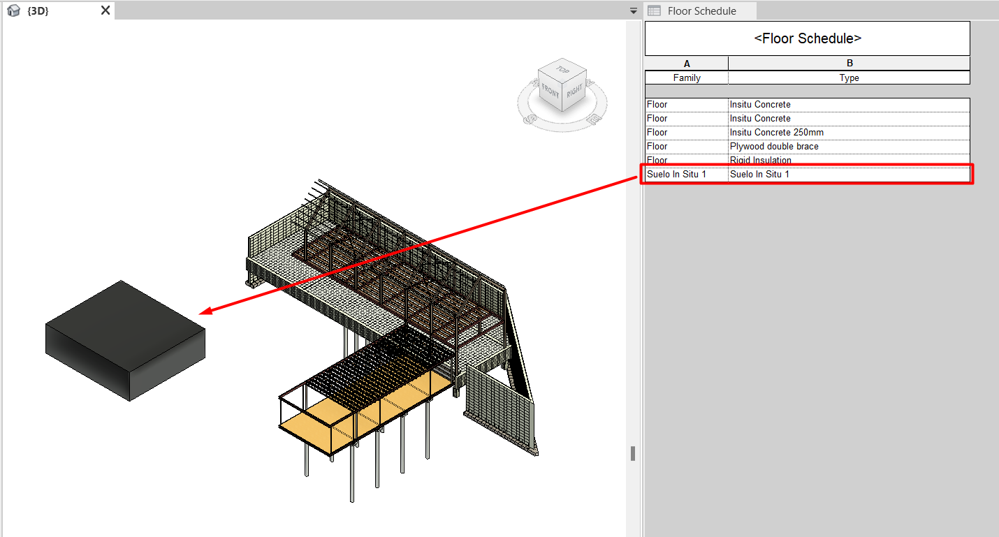
- The above point applies to all floors in the model, but not to those elements model In-place (Architecture tab > Component > Model In-place) that have been given the category 'Floor'.
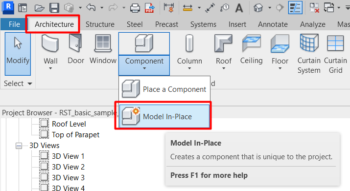
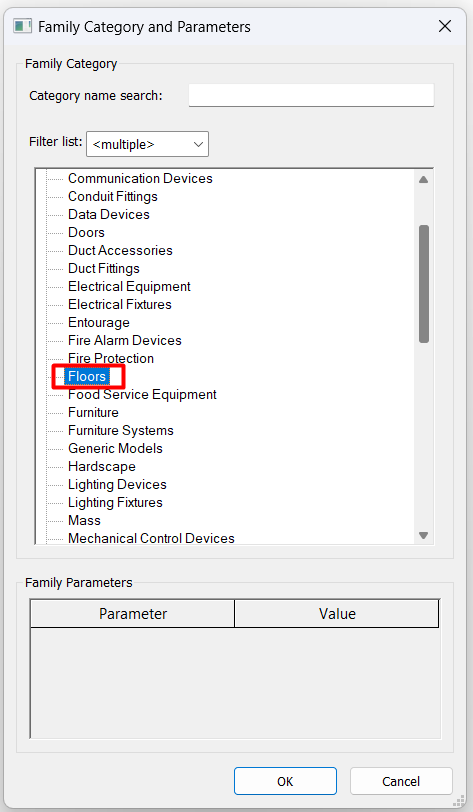
These components will appear in the Floors schedule and in the 'Family' parameter will appear the name we have given them when we created them. However, these elements are not floors as we have described them in this guideline, they will not have any of the parameters we have mentioned in the Properties chapter and we recommend limiting their use to the minimum necessary for the project.
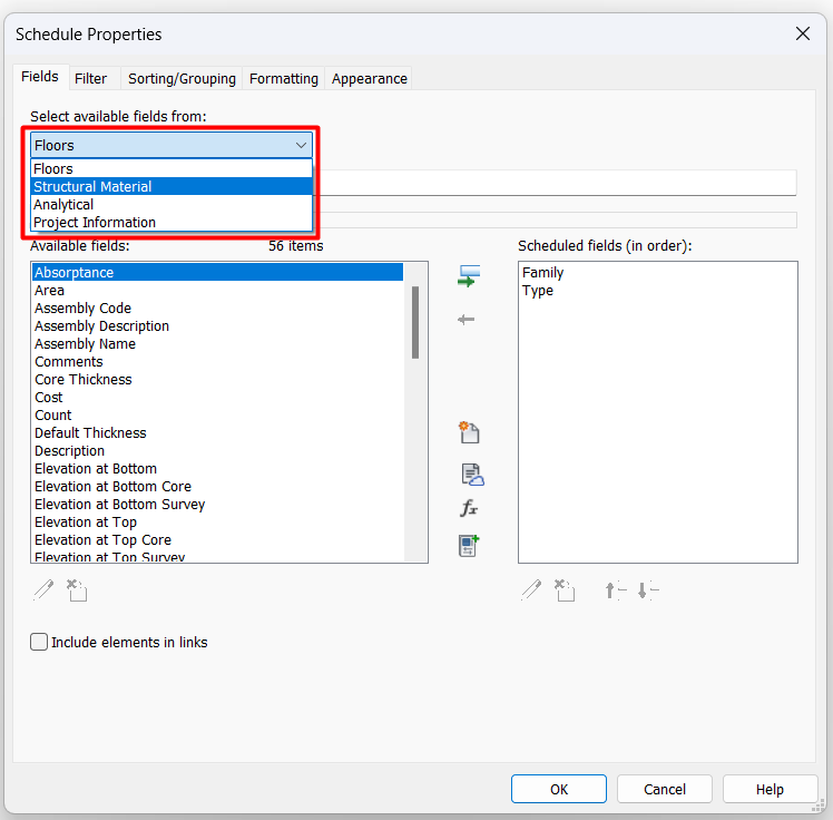
- Within the 'Fields' section of the Properties menu we can choose the following fields: Floors, Structural Material, Analytical and Project Information.
In most cases we are going to use only the Floors chapter, but in special cases such as structural models, we may be interested in extracting parameters of the structural material that forms each of the floors that appear in the schedule.
- It should be noted that in order to correctly manage the layers materials, it is necessary to use the schedule of type Material Takeoff, as the Schedules/Quantities schedules do not show the detailed floor structure.
- Although most of the parameters can be managed from the schedule, there are some that are not displayed there. For example, the Room Bounding parameter and the Perimeter parameter, the copy parameter which is found in the Dimensions section.
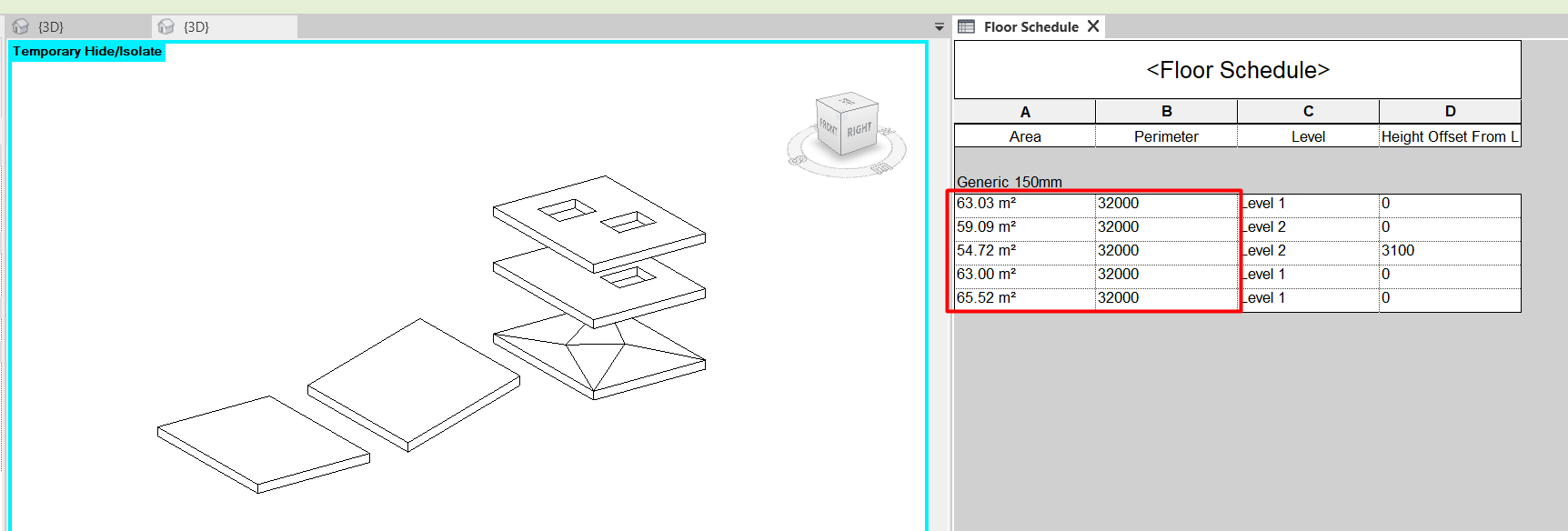
- If we modify the surface of a floor, giving it slopes, or creating holes, its area will be automatically updated in the table reflecting the real surface of the top face of the floor.
Slab edges
In opposition to the floors, the floor slab edges do have some particularities.
- Like floors, slab edges are system families, so we will always filter them by the Type parameter, not by the Family parameter. In this case, moreover, there is no possibility of creating in situ components of this category, so there will be no case in which we will be interested in filtering by the 'Family' parameter.
- While floors are created from a boundary and their main parameter is the area, Slab Edges are created from a line, and therefore their main parameter is the Length. In this case, we cannot use parameters such as Area or Perimeter, but we can use Volume, which multiplies the Length by the area of the profile used to create the edge.
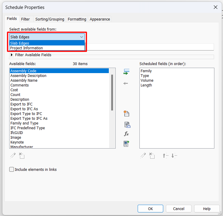
- For this type of families, the only available fields we have in the 'Fields' section of the Schedule Properties are Slab Edge and Project Information.
Naming Criteria
It is important to follow a well-defined naming criteria for the different floor types created.
Normally, there will be a pre-established naming convention in the BEP of the project to follow.
Here is an example of a naming convention for Architectural floors:
Project_Company_Discipline_Category_Code or Material_Description_Dimension
Example: AKS_MOD_ARC_FL_WOOD-01_WoodFloor_30mm
The benefits of correct naming are many:
- Identification of each element as a single component.
- Reading and identification of the elements without the need to see their internal properties.
- Use of a single common language for all project members.
- More efficient search and filtering of information.
- Order and structure of the elements.
- Storage of summarised information in models or other documents.
- Linking of elements with databases.
For more information, please see our guideline for Coding BIM projects
Conclusion
Floors are one of the main tools in Revit, fundamental in the design and modelling process of a building.
We have a wide range of options to configure and edit them, from managing their layers, to editing slab edges, slopes and slab holes, and this is precisely why we must be very careful with this tool. Correct and consistent editing of the layers will allow us to extract accurate quantities of the materials used in the project. In addition, it is vital to have correctly coordinated slab holes in our models and with all our partners to ensure that crucial facilities such as lifts or staircases can be accommodated throughout the vertical of the building.
To ensure all of this, it is important to carefully control all of our tools, preventing them from being moved or edited without sense, as an error in these elements can lead to a very high cost overrun in the final stages of the project.
Tips & Tricks
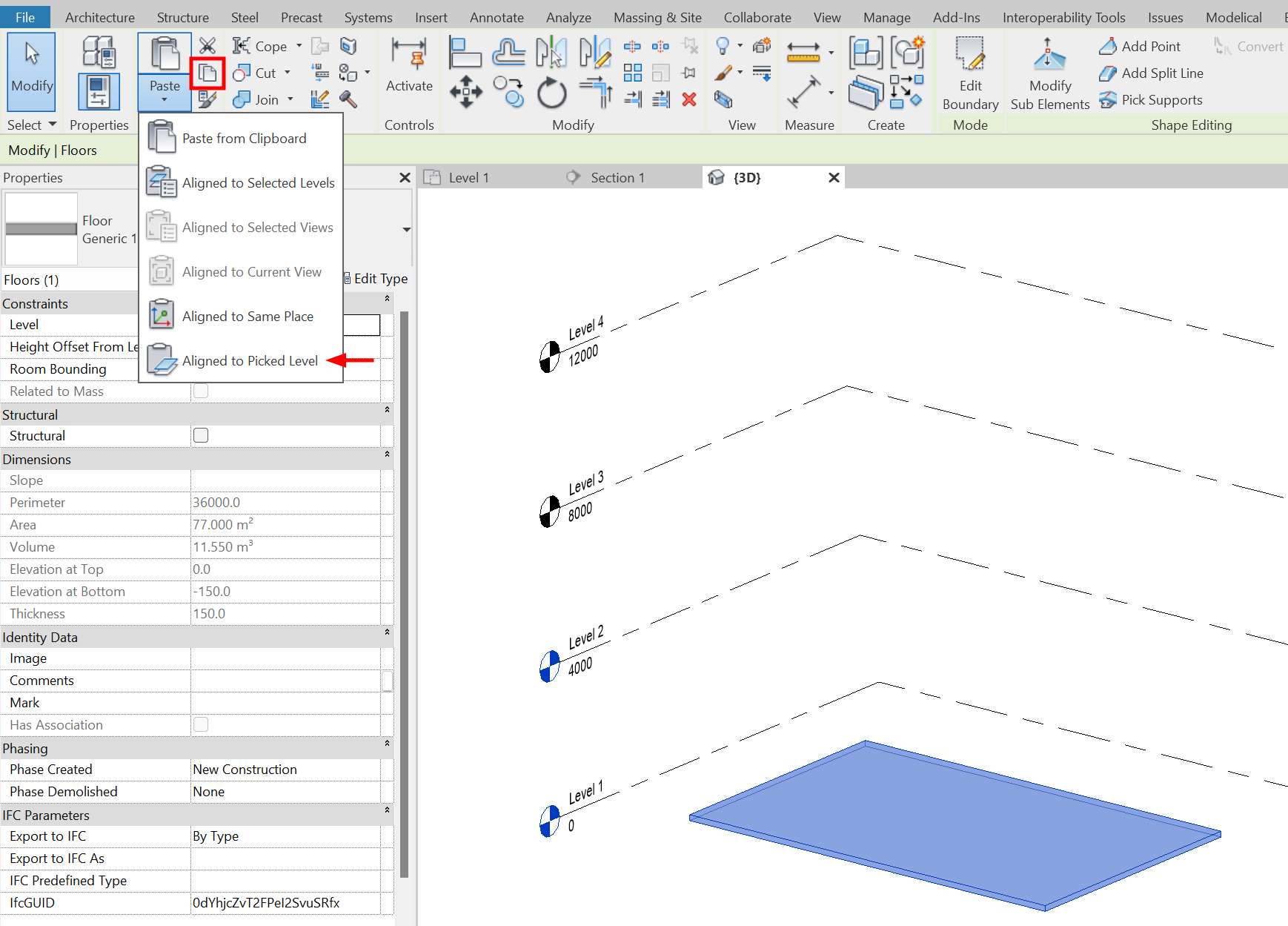
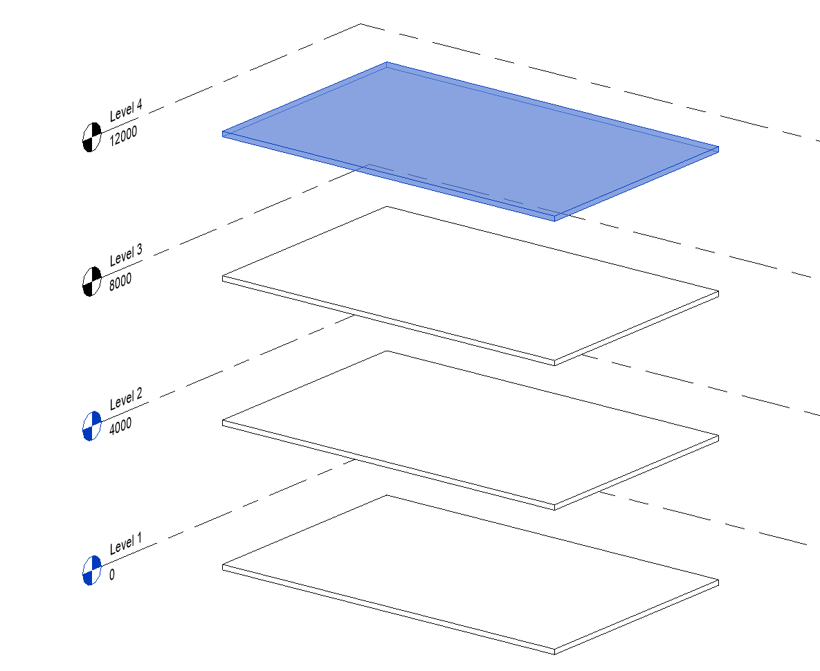
- Floors belonging to a level can be copied using Copy to clipboard and then Paste them by selecting the option Aligned with selected levels. They can be copied to several levels at the same time.
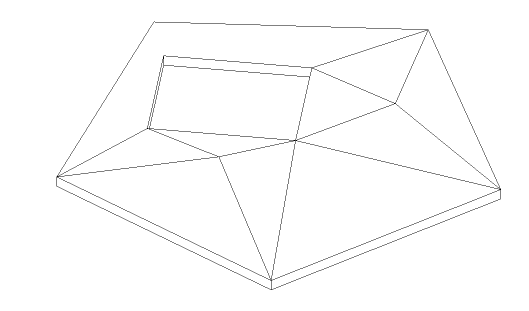
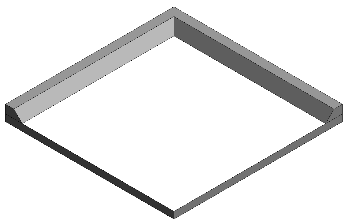
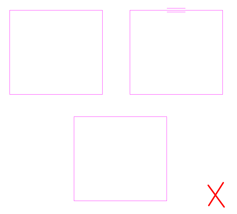
- It is recommended to create floors with a single perimeter boundary. It is a bad practice to have a floor composed of several boundaries (image below) as it creates multiple loops and may slow down the model.
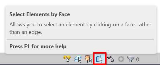
- A floor can be selected from a boundary line or by face. To select by face, the option Select elements by face in the lower right corner of the interface must be activated.
- Floor boundary lines can be locked to an element such as a grid or a wall. This is not usually recommended as the shape of the floor boundary can drastically change and consequently lead to an error.
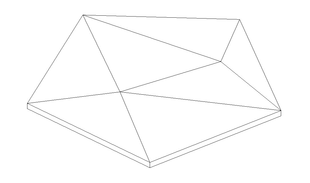
- If we have a sloped floor, for example, on flat roofs, and we have to create an internal opening, it is recommended to generate a hole that goes through it avoiding modifying its slopes.
To do this, use the Openings tool.
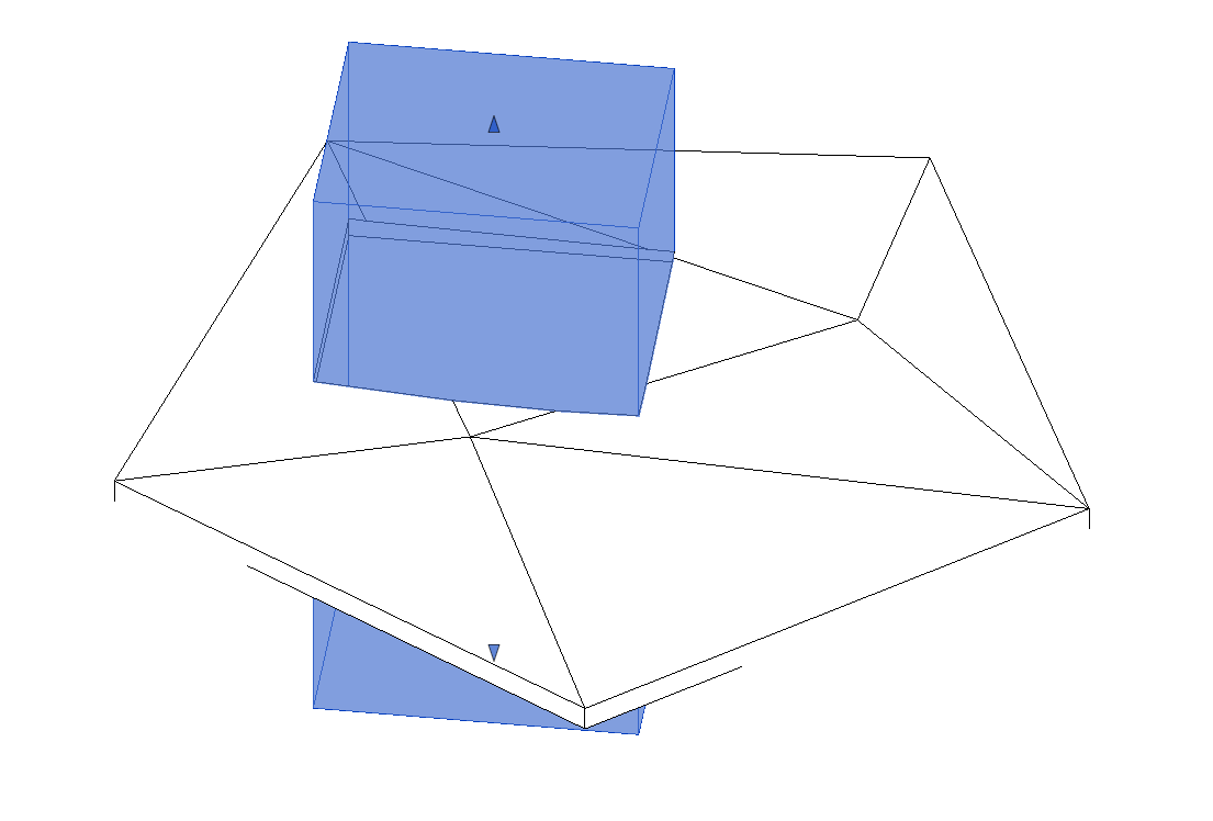
On the contrary, if we generate the opening by modifying the inner boundary of the floor, our slopes will be modified by this new boundary and it will be very difficult to handle them correctly.