

Keynote and Assembly Code
Keynote and Assembly Code
Version
This guide is based on the functionalities of Revit version 2023.
Objectives
- To understand what keynote and Assembly Code parameters are and how useful they can be.
- Create and import a Keynote and Assembly Code file.
- Create and include Keynote legends in drawings.
- Assign Keynote and Assembly Code parameter values to Revit model elements.
- Assign codes of different classification systems quickly using the BIM Interoperability Tool: Standardised Data.
- Create customised classification systems using the BIM Interoperability Tool: Standardised Data.
Prerequisites
- The user has basic Revit modelling skills as well as BIM skills.
- The user has a spreadsheet program (Excel, GSheets), a text file reader (Notepad) and Revit.
- To use the Standardised Data add-in, the user must download and install the Autodesk Interoperability Tools package according to the version of Revit being used.
Overview / Introduction
In Revit, there are system parameters that allow us to enter values in a model’s families and link them to an external classification system based on a text file. These parameters are: Keynote and Assembly Code. In this guide we will see how to create these files to configure and assign both parameters in Revit.
In addition, we will go into detail with the Standardised Data tool included in the Autodesk Interoperability Tools add-on. This is a very interesting tool that allows us to generate new custom classification parameters and to massively code the model elements.
1. Keynote
Description
It is a type parameter included by default in all model elements (even in detail components) and materials, which is usually used to generate code legends to identify different types of construction elements. They appear in tables and can be labelled.
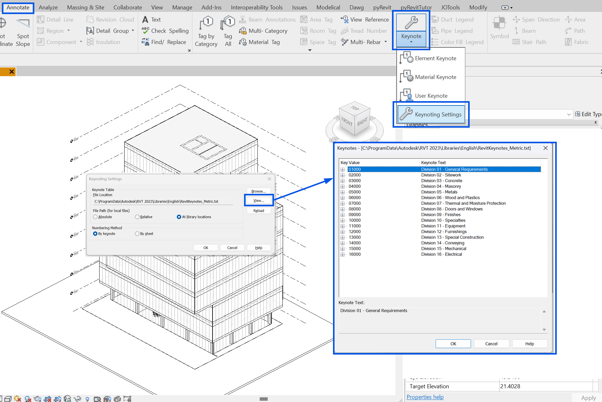
The information included in this parameter can be associated with a txt file. By default, Revit includes a default one, but you can use a different one with the system that suits you best. To access the Keynote file configuration we will have to go to Annotate> Keynote> Keynoting Settings.
Keynote Types
There are three types of Keynote. Depending on the labelling or classification needs, we will have to configure our text file in this way, including codes for element types, for materials and for comments, since there will be only one Keynote file available. In other words, all types read from the same txt.
The types of Keynote that we find are element, material and user:
- Element keynote: It is a type parameter that can be applied to any element of the model (including detail components).
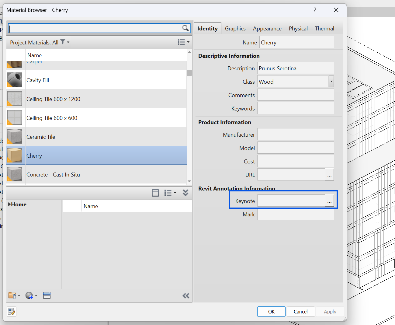
- Material keynote: When a keynote is assigned to a material, objects using that material inherit the keynote value.
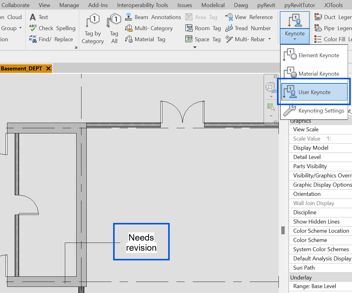
- User keynote: These can be used as annotations or comments on documentation. Unlike the other two, this is an instance parameter. It only affects the view in which it is found and does not modify any properties of the element. User keynotes should be used with caution.
Keynote Legend
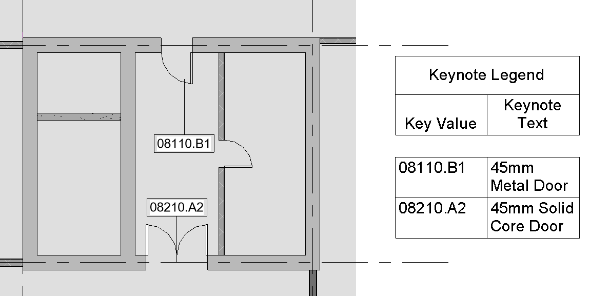
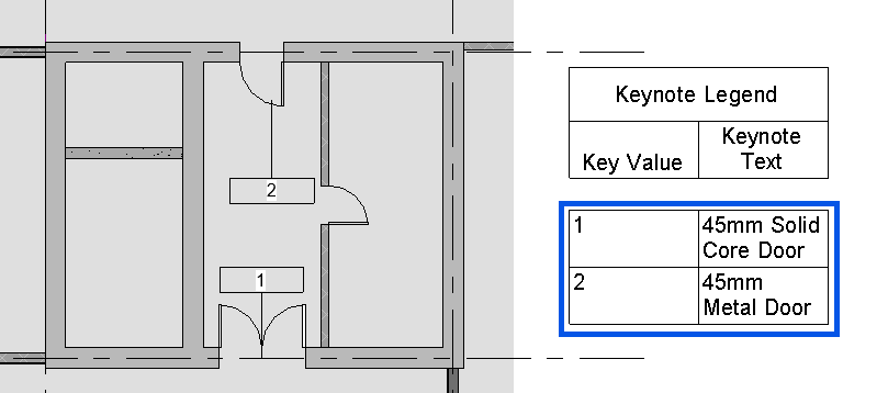
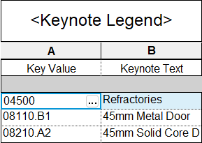
Since the most common use of keynotes is tagging, Revit has the option to generate Keynote legends in View > Create > Legends > Keynote Legend. The legends will include a listing of all Keynotes contained in the model.
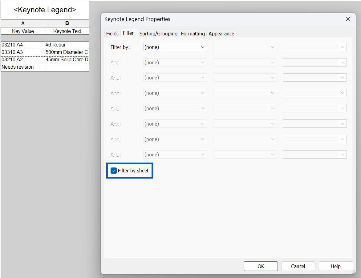
These legends work like a schedule that can be placed in plans. You can work with its Fields, Filter, Sorting/Grouping, Formatting and Appearance properties in the same way as with any other schedule. In addition, in the schedule’s Filter tab there is the option to Filter by plan, so that only the codes of the elements that are visible in that plan appear in the legend.
How to create a Keynote file?
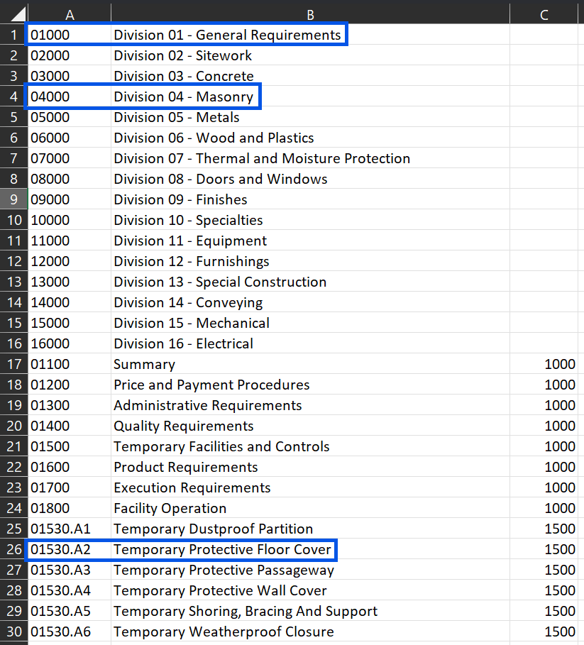
The Keynotes codes and their descriptions are defined in tab-delimited text files. To create a new list, open a spreadsheet or Excel spreadsheet with three columns:
- The first column will contain the Keynote Value.
- The second will contain the Keynote text.
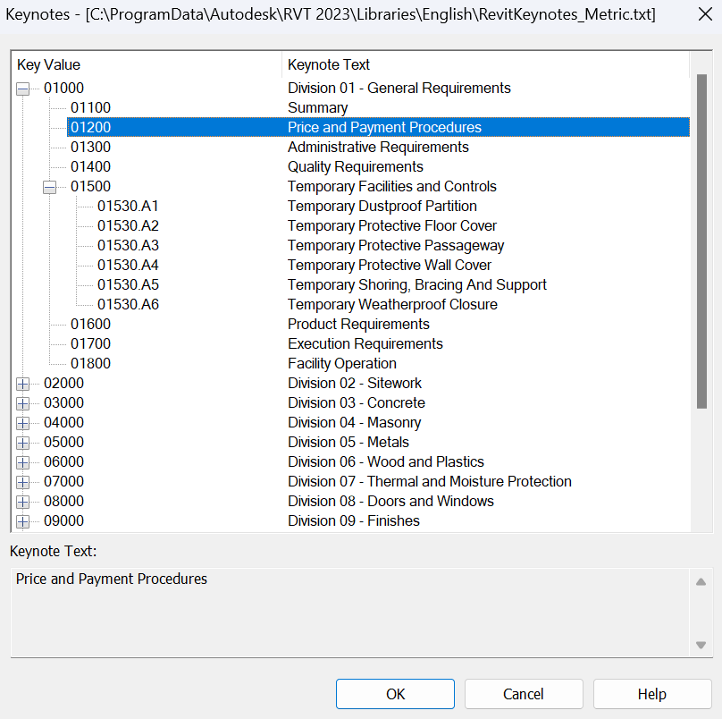
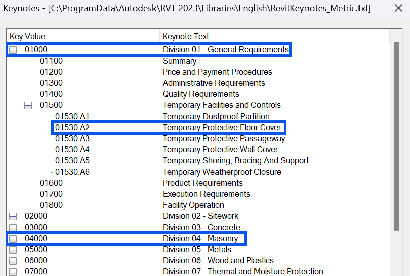
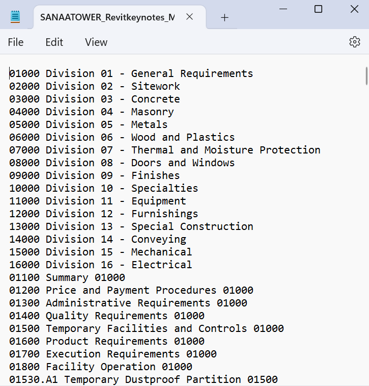
- The third column will contain the Nesting Control Value. That is, for each line it is indicated under which code of the first column it is nested. In this way, once imported into Revit, the information will be properly grouped in a tree structure.
In the following images we see how the lines with code 01100 or 01200, will be grouped under line 01000 and lines 01530 under 01500.
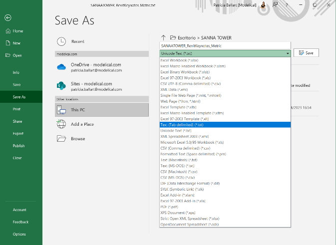
Once the Excel sheet is prepared, it will be necessary to save it as a tab-separated text file (.txt).
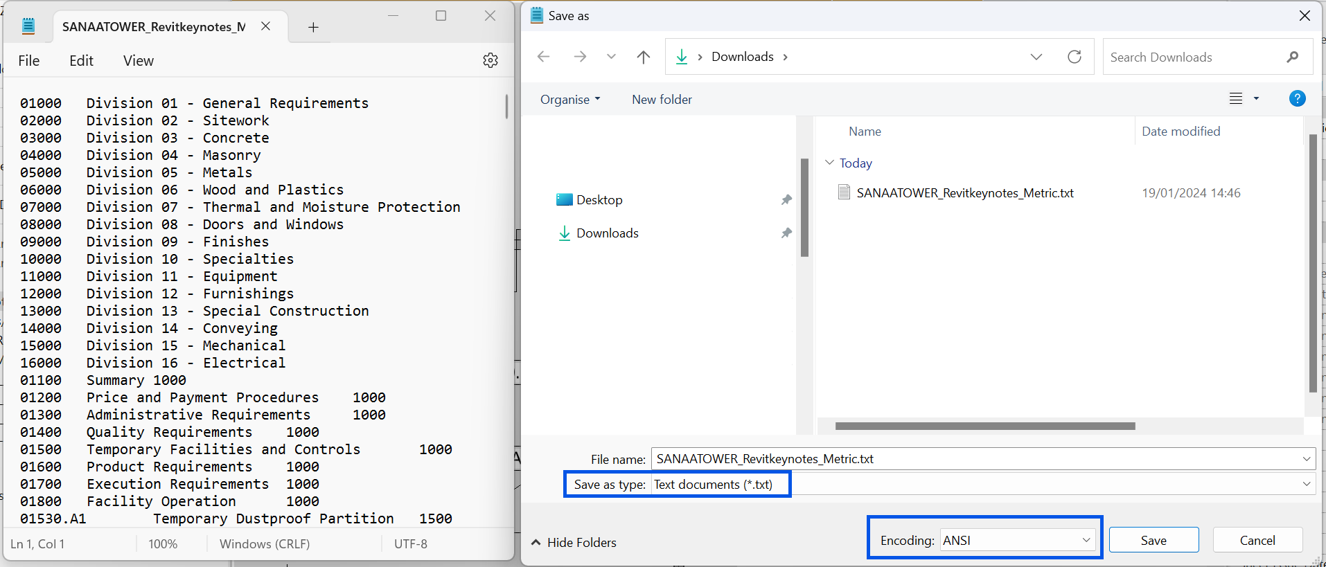
It will then be necessary to open that .txt file and save it in ANSI or Unicode format to avoid problems with file encoding or decoding. For example, to allow the text file to recognize special characters, such as accents.
Finally, we will browse for our file in Revit from Annotate> Keynote> Keynoting settings > Browse.
How to upload or edit a Keynote file?
From the dialog box located in Annotate>Keynote>Keynoting settings, we can specify the keynotes file we are going to use, reload it or view it for checking. We can also edit it from Keynoting settings> Browse, right click on Edit on the keynotes file and the file will open in txt format.
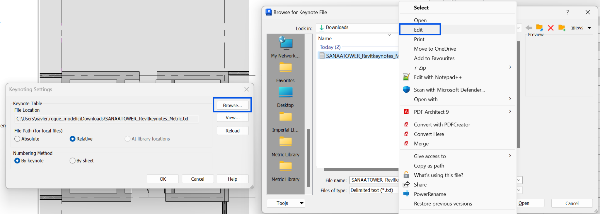
The Keynoting Settings dialog box consists of three parts:
File location
In the first part appears the path where we must specify the location of our keynote file in .txt format. With the buttons on the right we can:
- Browse: specify the path where the file is located. This path must be exactly the same if we want to use the same text file in different linked models.
- View: allows us to view the text file that appears in the specified path.
- Reload: if we have modified the text file, this button allows us to reload it without modifying its file path.
File Path
The location of the currently loaded Keynote file is shown at the top of the dialog box and the path can be of type:
- Absolute. Identifies a specific saved folder, in which case the specified location must match exactly.
- Relative. It looks for the keynotes file in the location of the project file or the core model. If that file changes location, Revit assumes that the keynotes file is also in the new location.
- At library locations. Refers to the default location of the keynote creation files.
Numbering method
It is possible to work with the codes in the .txt file of the "Keynote" or to change them to an independent, consecutively ordered list for each plan, starting with number 1.
Annotate>Keynote>Keynoting settings>Numbering method
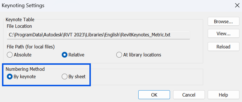
The numbering method can be:
- By keynote. Determines the Keynote value according to the keynote file. This value is displayed both when tagging and in the Keynote parameter.
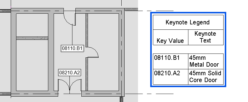
- By sheet. Assigns a number in order of creation, but the value of the Keynote parameter is retained, if one has been previously chosen. The label does not display any number until the view with keynote labels is placed in a plan view.
How do we assign the Keynote?
Element keynote
To assign the Keynote, we have two options:
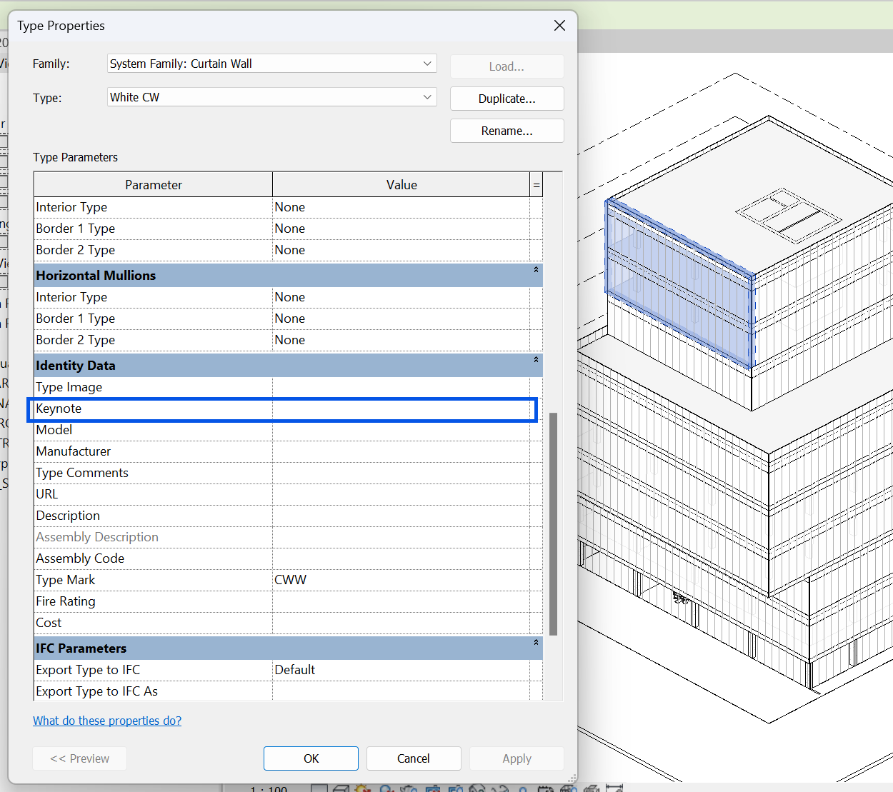
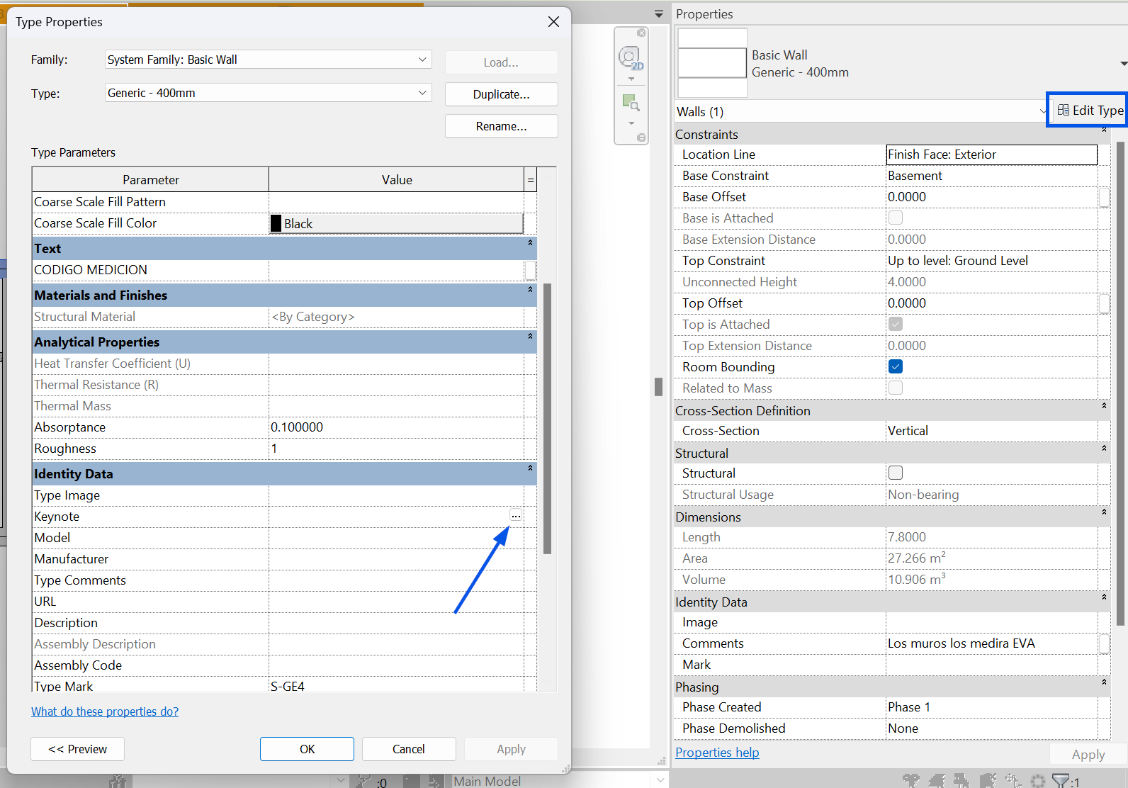
- From type properties. If the element type is edited, within Edit type>Identity data>Keynote, three dots will appear inside the checkbox. Clicking it will open the keynotes file, allowing selection of the desired code. Alternatively, the code can be entered manually.
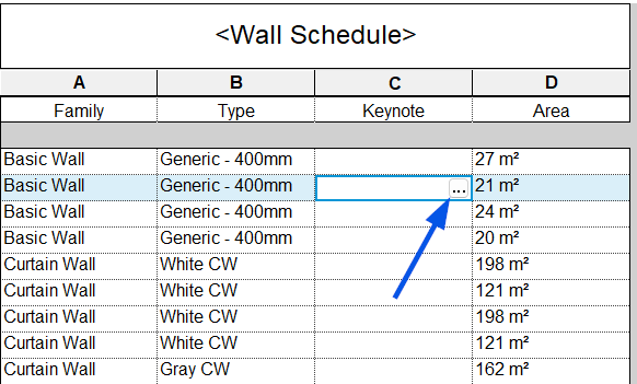
- From a Schedule/Quantities. It will only be necessary to select the keynote field when creating our table and from there we can open the dropdown in each of the elements. It could also be entered manually.
Material Keynote
As in the case of element Keynotes, we also have two options for assigning a Material Keynote:
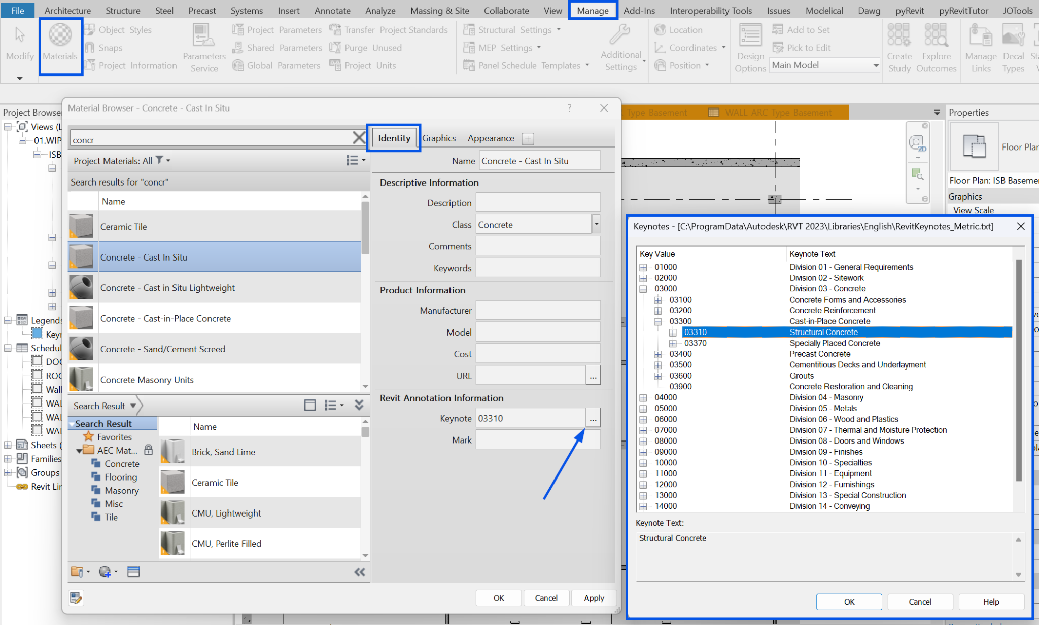
- From the material browser. In Manage > Materials > Select Material > Identity > Revit Annotation Information > Keynote. We can display the Keynote tree by clicking on the three little dots’ box in the Keynote field or enter the Keynote value manually.
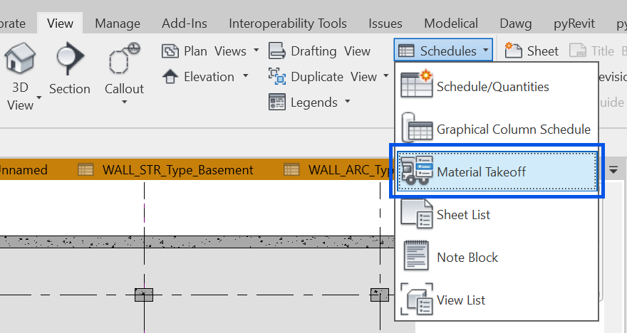
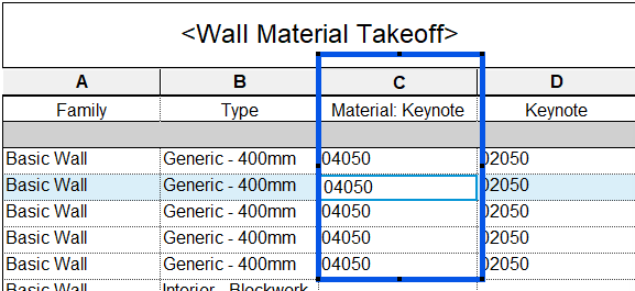
- From a Material Takeoff Schedule. To do this, we will have to open a specific material takeoff schedule and select in Material Takeoff Properties the field Material: Keynote.
From the Material: Keynote cell we can open the classification file and select the desired code or add it manually.
User keynote
To add a user keynote, note that this option is only accessible when annotating in a view. Click on Annotate > Keynote > User keynote and select the element to be labelled. The Keynote can be modified by clicking on the label or even from the Keynote legend.
2. Assembly Code
Description
It is a type parameter of the Revit model elements usually used to add information to them in order to classify them according to the criteria you consider. For example, you can match an element to an item code in the budget.
Unlike the Keynote it is only possible to assign them to elements, not to materials.
How to create an Assembly Code file?
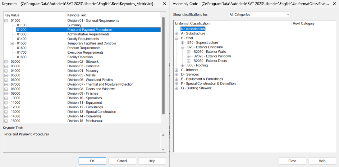
The Assembly Code file should be similar in structure to the one found in the Revit library called UniformatClassifications. It is located by default in Local Disk C: > ProgramData > Autodesk > RVT 2023 > Libraries > English > UniformatClassifications.txt
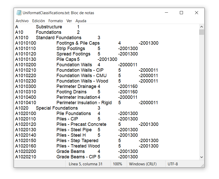
This will require a spreadsheet with four columns:
- The first one will contain a code (parameter Assembly Code).
- The second one, a description (parameter Assembly Description) corresponding to that code.
- The third will contain a value from 1 to 5 (unlike with the Keynote, the Assembly Code tree cannot have more sublevels), indicating the hierarchy order (Rank) in which the row in question should be grouped. This will allow, once imported into Revit, the information to be properly nested in the structure tree.
- Finally, the fourth column is optional, but greatly streamlines the coding of elements. This indicates the Category Code of the element in Revit (Revit Category ID), and allows us to, at the time of assigning a code to an element, have available only the options associated with the Category of that element.
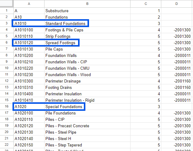
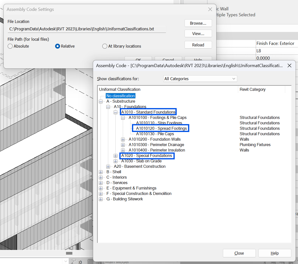
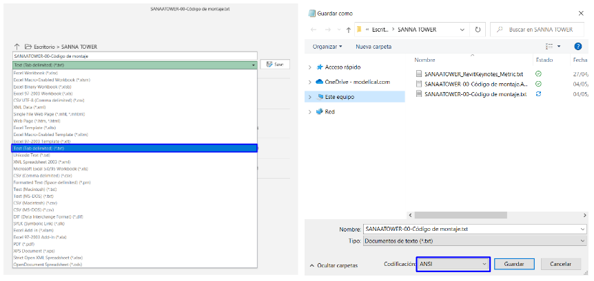
Once the Excel sheet is prepared, it must be saved as a tab-separated text file (.txt). Finally, it will be necessary to open this .txt file with Notepad and save it in ANSI or Unicode format.
How to upload or edit an Assembly Code file?
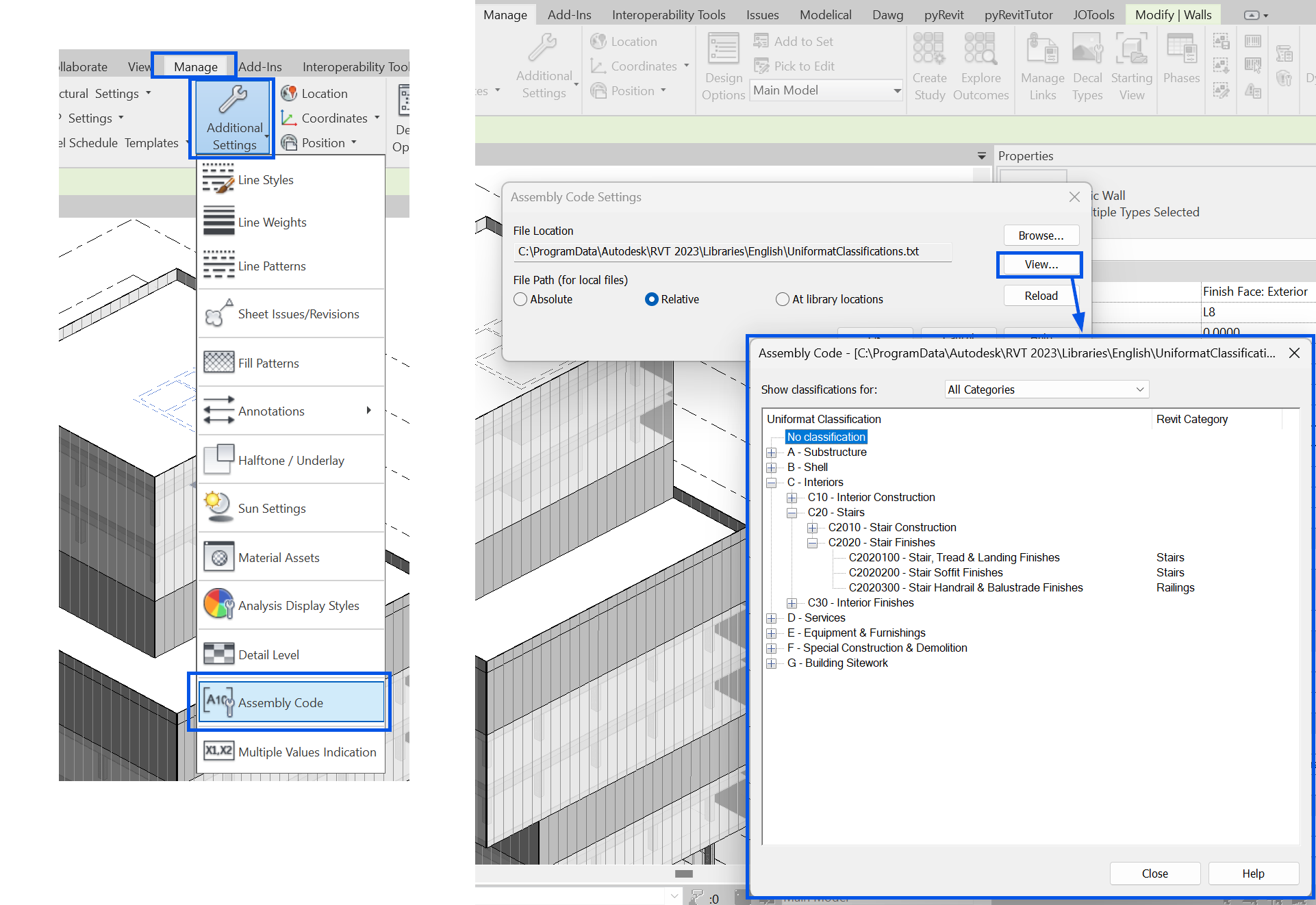
From the dialog box located in Manage> Additional Settings> Assembly Code> Assembly Code Settings, we can specify the assembly code file to be used, reload it or view it for testing.
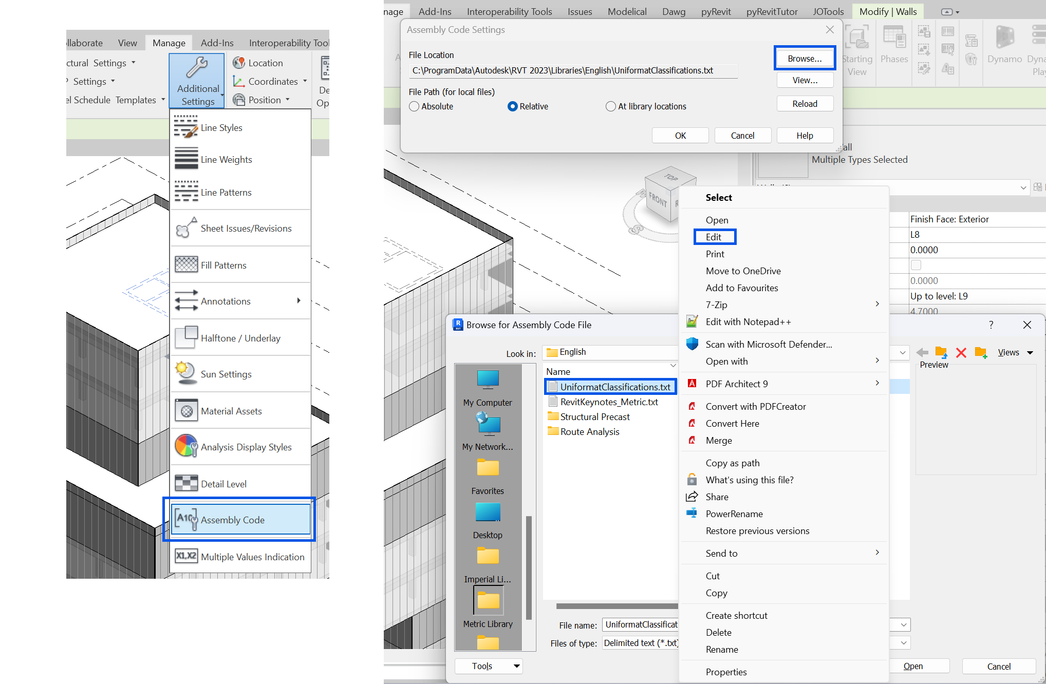
The Assembly Code Configuration dialog box consists of two parts:
Location
In the first section we must specify the location of our assembly code file in .txt format. With the buttons on the right we can:
- Browse: specify the path where the file is located. This path must be exactly the same if we want to use the same text file in different linked models.
- View: allows us to view the text file that appears in the specified path.
- Reload: if we have modified the text file, this button allows us to reload it without modifying its file path.
File path
As with Keynotes the location of the .txt file will be displayed at the top of the dialog box and the path can be of any type:
- Absolute: identifies a specific folder stored on the local computer or on a network server.
- Relative: looks for the keynote file in the location of the project file or core model.
- At library locations: refers to the default location of the keynotes creation files.
How do we assign the Assembly Code?
As in the Keynote, there are two options for assigning the Assembly Code:
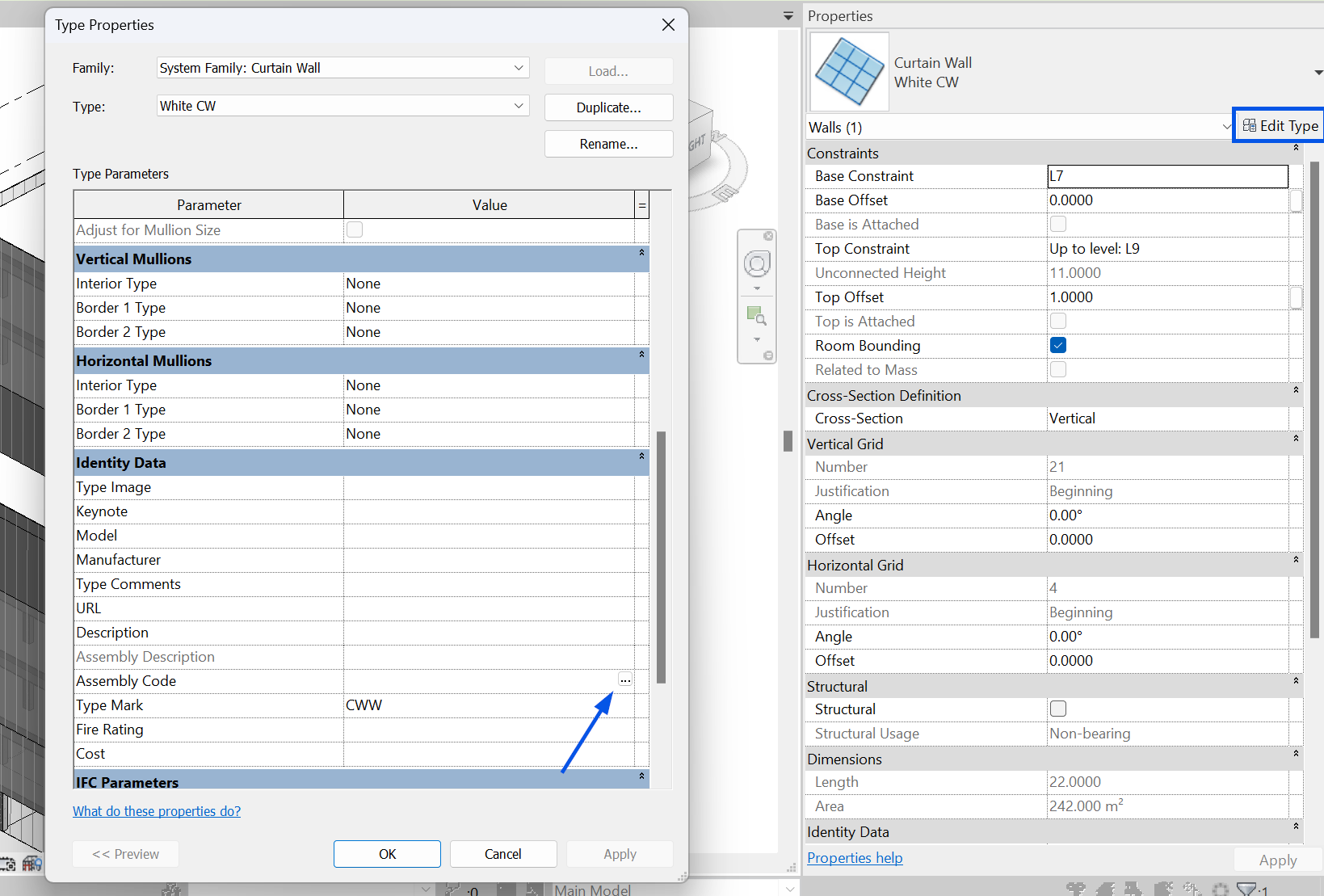
- From type properties. If we edit the type of the element, in Edit Type>Identity Data>Assembly Code, three little dots will appear inside the type box. Clicking it will open the keynote file from where we can select the desired code. We can also enter the code manually.
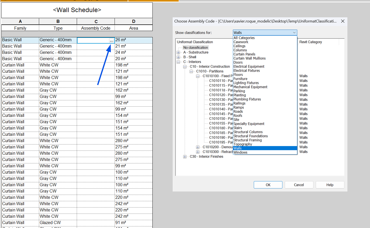
- From a Schedule/Quantities. Assigning the codes from a Schedule is very useful since we can sort our elements by category, family and type. In the Schedule, we should add the Assembly Code field when we create our Schedule and from there we can open the dropdown for each of the elements. We can also enter the codes manually.
3. BIM Interoperability Tools
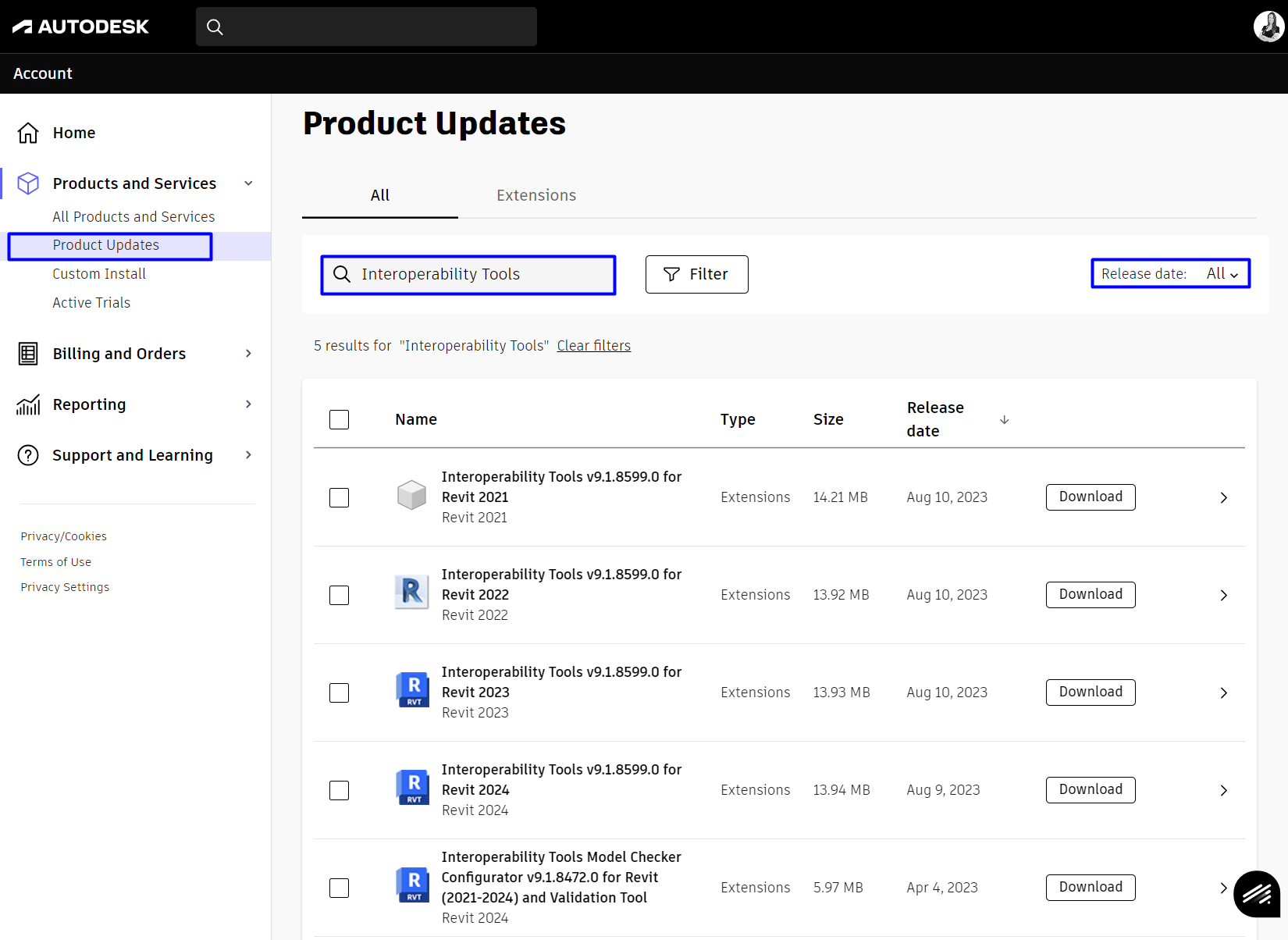
Another method of assigning the Assembly Code is by using one of the tools that is part of the BIM Interoperability package: Standardised Data for Revit (Classification Manager in previous versions). You can download BIM Interoperability Tools from the Autodesk Desktop Application where we can choose the version, or from its official website biminteroperabilitytools.com.
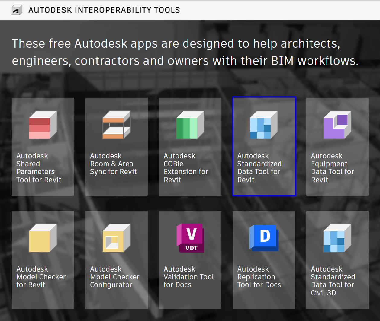
With this addin, we can:
- Assign multiple classifications to items at once, or apply the value of only one classification system to several selected items.
- Not only can we create custom databases, but we can also generate new user-defined parameters and assign the classification to them.
Classification Systems
In BIM Interoperability Tools we will find two options:
- Assign Classification, from where we can select a database and sorting objects.
- Assign Picklist, which is nothing more than a direct link to the customizable picklist for adding custom databases.

From both tools we can access Options where we can choose one or several public classification systems from the library or add the path of one that we have previously configured in Picklists > Add Path. From this same screen we can download and edit the different classification systems.
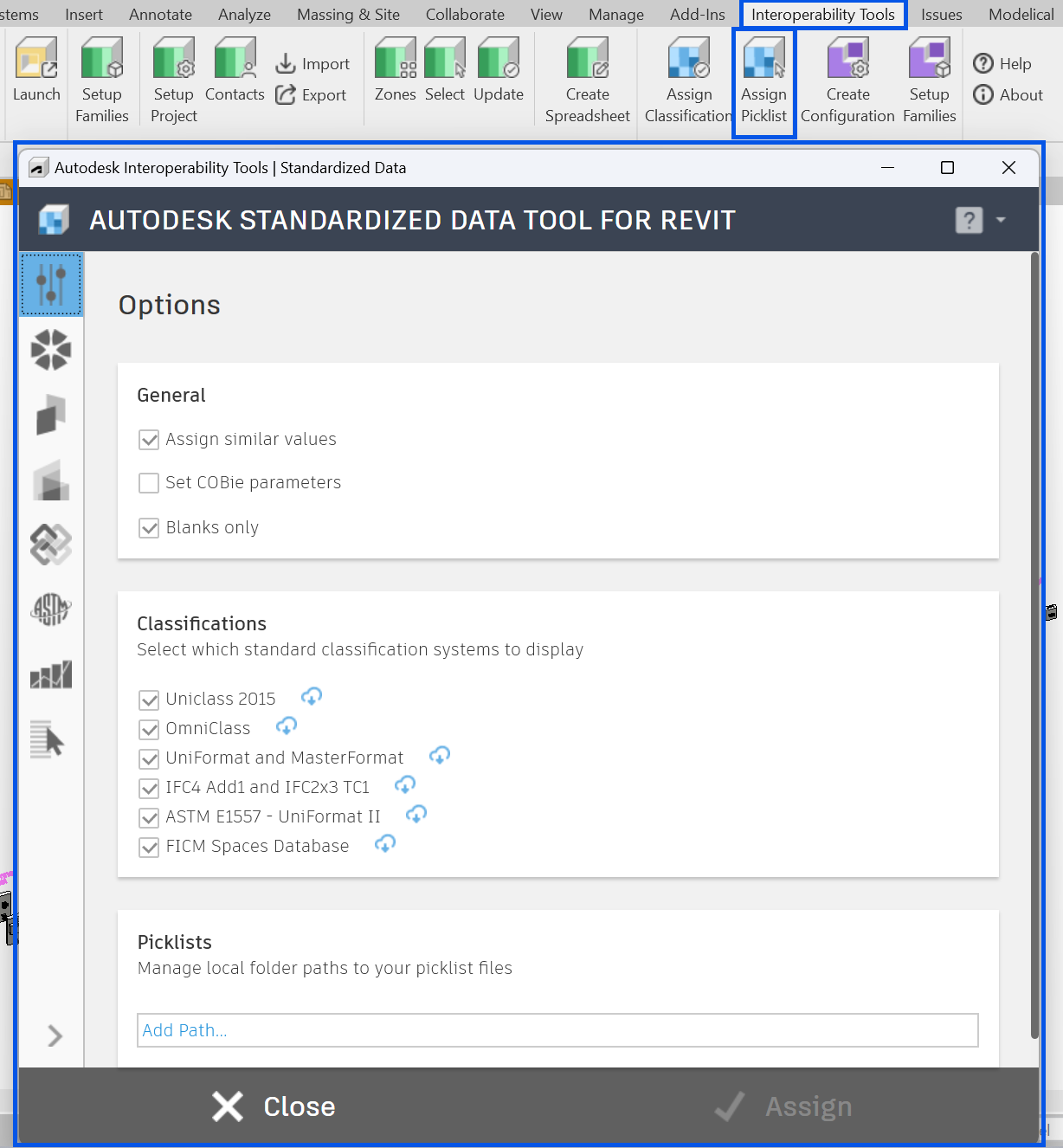
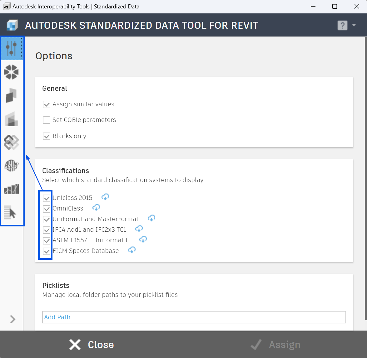
We can select as many classifications as we are going to use. These will appear as icons in the left sidebar. However, in a model we will only be able to load a single custom classification and this will always appear in the last position: Picklist.
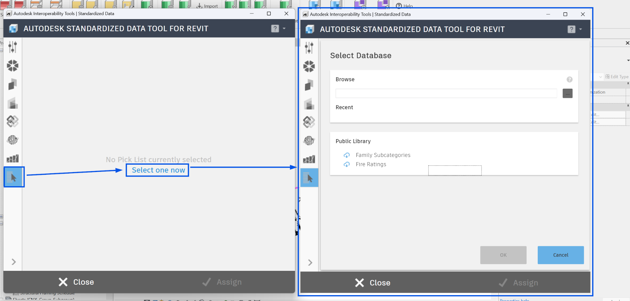
To load our custom classification, we can do it from the Options tab or from Picklist. We can also reload a database that we have already used previously.
How to create a Customised Classification?
The Public Classifications library is stored by default in the folder Local disk (C:) > Program Files (x86) > Autodesk > AIT > 20XX > Resources. Here we will find the template to create our own custom classification.
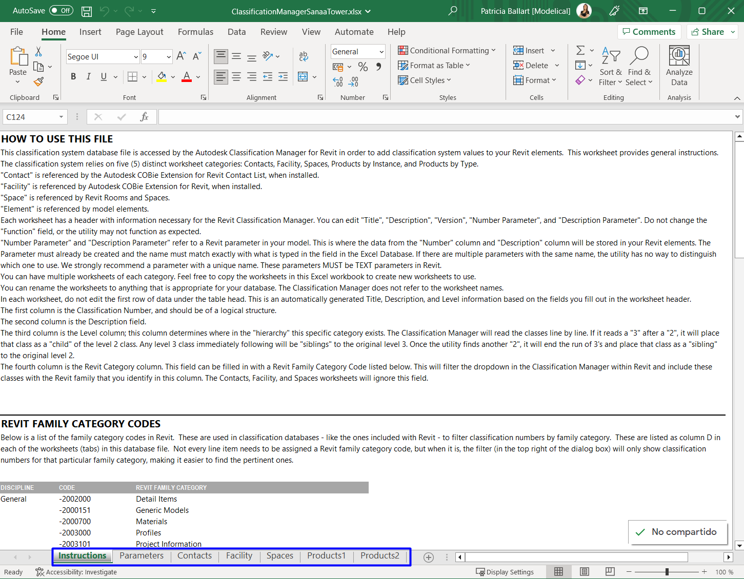
The first thing to note is that this tool reads Excel files. If we open the Excel Classification Manager Database Custom file, we will find a series of sheets:
- Instructions
- Parameters
- Contacts
- Facility
- Spaces
- Products1
- Products2
Instructions
The first sheet is the general instructions, which explains step by step how to complete the document.
Parameters
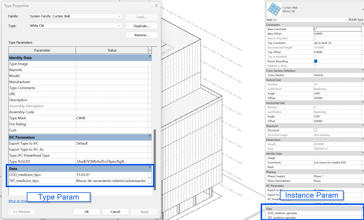
In the Parameters sheet we will create the custom parameters where we will assign the codes of our custom database. This sheet comes ready to copy/paste from an already created Shared Parameters text file.
The header should not be edited, we insert the information directly from the .txt in box B4. In column TYPE v INSTANCE, we will indicate if it is a type or instance parameter and in DATATYPE the data type. Only TEXT, INTEGER, NUMBER, YES-NO and URL data types are accepted.

Once we load our database into the model, it will automatically create the parameters if they are not already there. This is an effective and fast method for all the teams to encode correctly in the appropriate parameters.
Contacts and Facility
Both the Contacts and Facility sheets refer to another of the Interoperability Tools: COBie Extension, from where we can add contacts or manage areas and rooms. For this reason we will not explain them in this guide.

Spaces and Products
In the Spaces sheet, we will configure the classification of rooms and areas, and in the Products 1 and Products 2 sheets, those referring to the elements of the model. We can create as many sheets as we need Spaces or Products, depending on the parameters we need to define for each category.
For example, if we want to create two item classification parameters, one for type and one for instance, we will use the Products 1 and Products 2 sheets. Inside the header, the fields Parameter Number and Parameter Description refer to a parameter that we will have previously created and which name must match exactly with the one entered in the database. These parameters must be TEXT parameters in Revit.
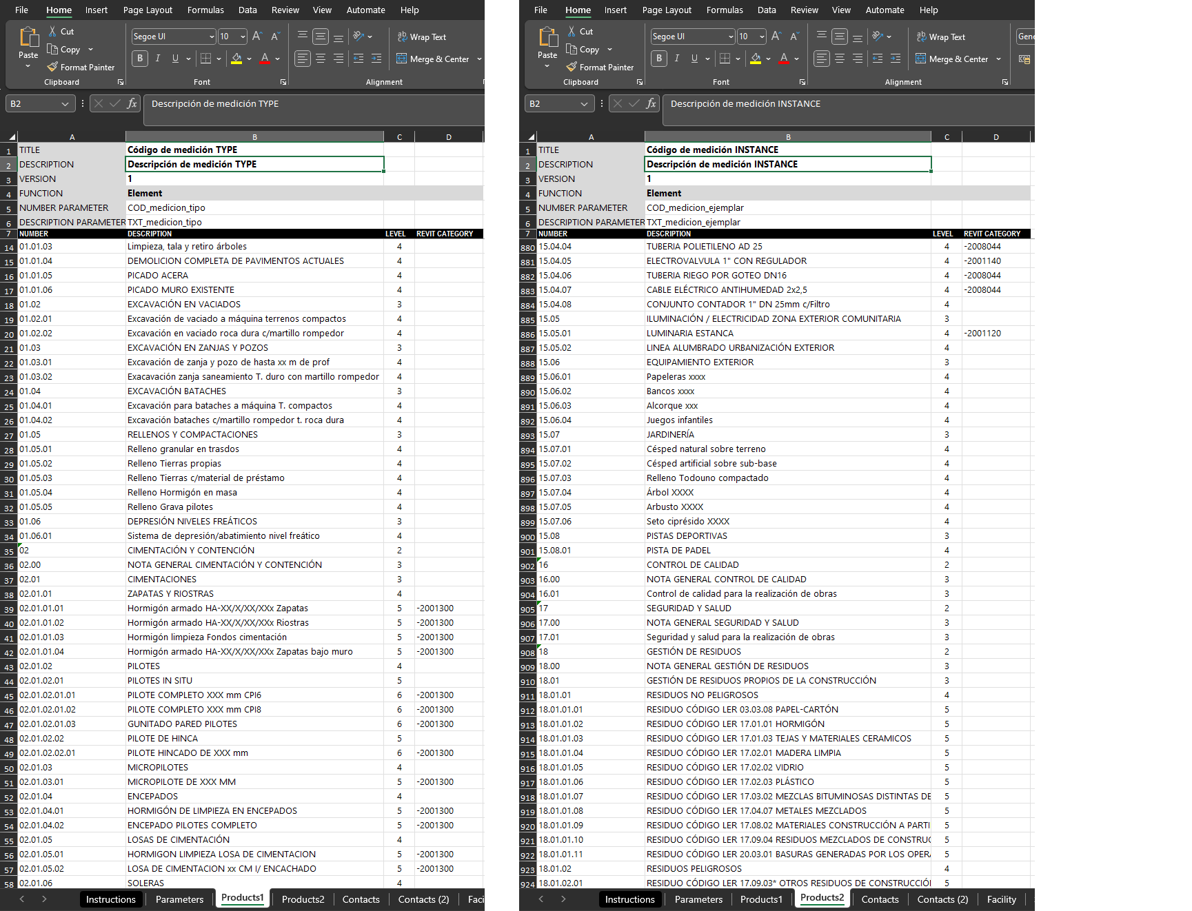
The Sheet is composed of four columns: in the first one we will indicate the classification code; in the second one, the description; the third one is the hierarchy level, how it will be ordered within the tree structure; and in the fourth column we will indicate the Revit Category ID. These can be found in the instruction sheet of this same file. This assignment will group the codes in each of the Revit categories, which will allow us to filter the list and speed up the coding.
Once we have all the fields filled in, we will save the file and in our Revit model we will load it in BIM Interoperability Tools > Standardised Data > Assign Picklist > Picklist and select our custom database.
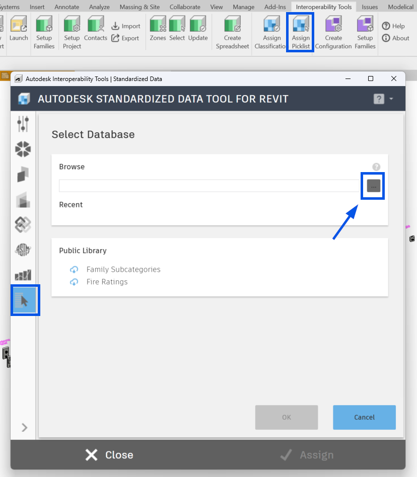
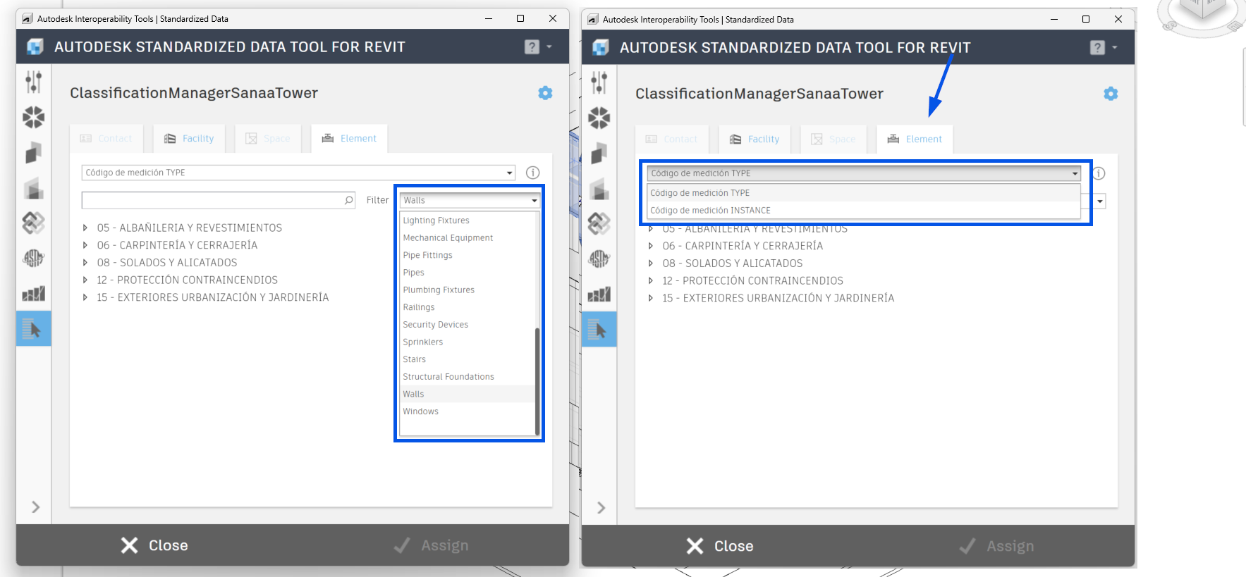
In our customised classification we will see that, in the Element tab, we can choose whether to code by type or issue, and we can also filter the codes by category, according to what we have classified them in our document.
Code assignment
Before proceeding with the assignment of codes and only in the case of using custom classifications and parameters, we must make sure that we have created the parameters in the corresponding tab in the Excel document (see How to Create a Customized Classification). Once this is done, assigning the codes to the elements will automatically generate the parameters in the model. Another option is to add them manually to the project from a shared parameters .txt file. If we don’t do it, we will get the following warning:
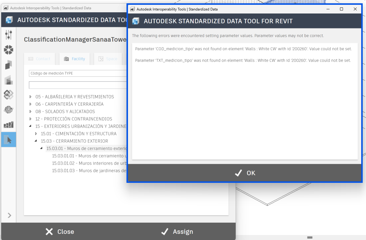
If we are going to use a standardised database, the parameters will be added to the model as we assign codes.
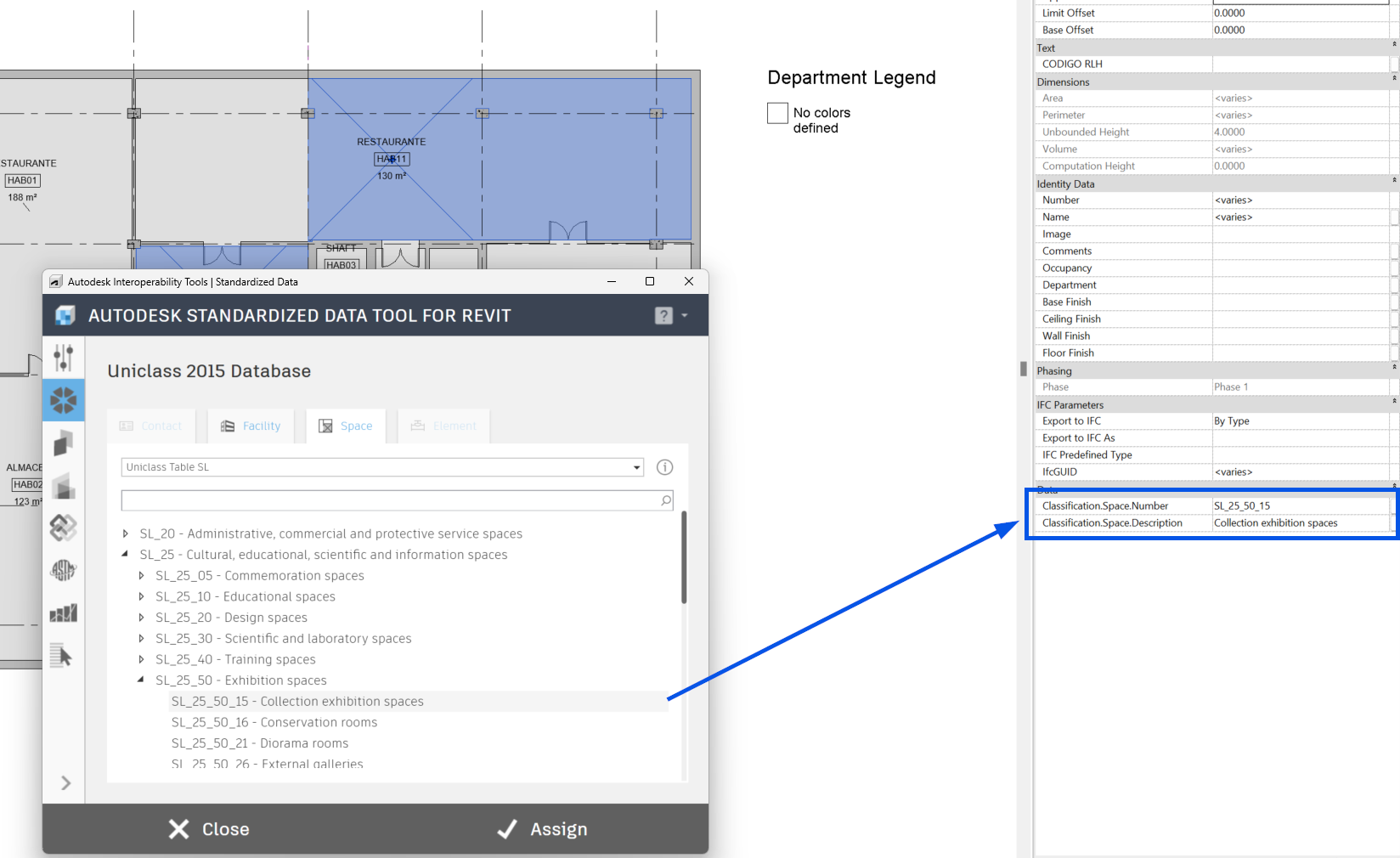
One of the advantages of this tool is that we can code one or several elements from one or several classifications at the same time. To do this we will select the elements in the model and in BIM Interoperability Tools > Standardized Data > Assign Classification, we will choose the codes of the different classifications, clicking Assign in each one of them.
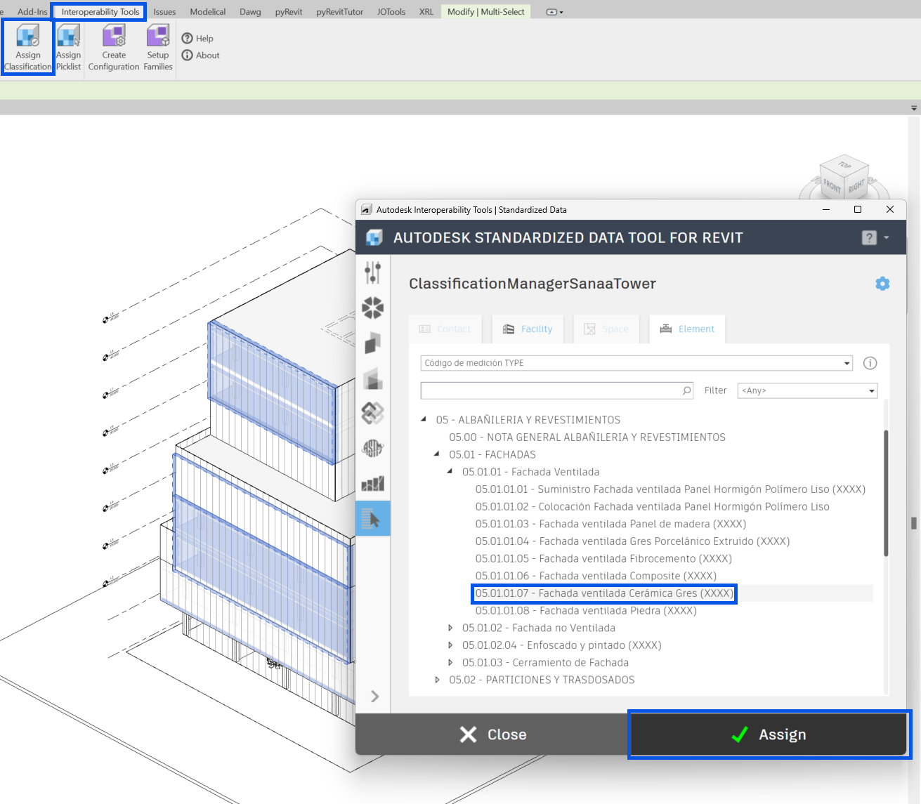
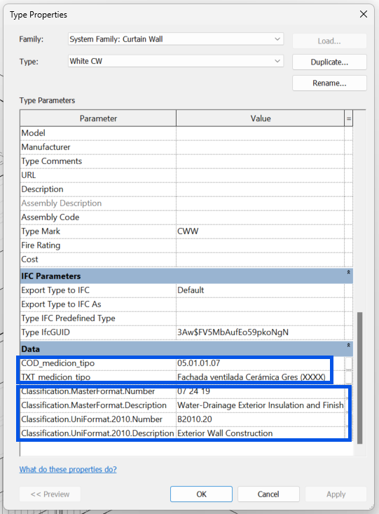
We can enter classification values in elements both by type or by instance, as well as in rooms or spaces:
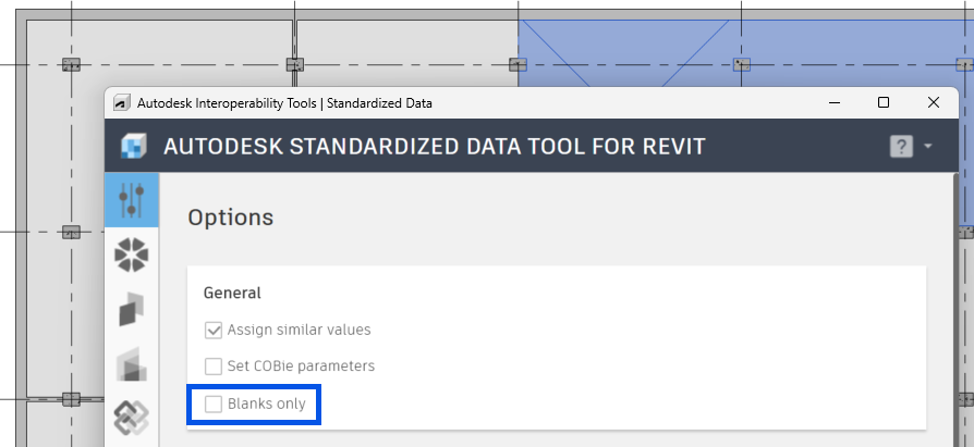
One thing to note about assigning classifications is that we have the option to fill in only the blanks or overwrite the values that have been previously assigned. So, if there is already a classification configured for some elements, it can be assigned only to those that do not have a value.
Summary
Both the Keynote and Assembly codes are type parameters that allow us to relate the elements of our model to external data files.
These external files can be standardised classifications or we can generate our own. They are parameters that work in much the same way but their use is often applied differently. Just as Keynotes are usually used for labelling and legends (although in some cases they are used for the extraction of measurements by material), Assembly codes are very useful in the extraction of measurements, since they are coded according to the constructive function of the elements. Many budgeting programs such as Presto, Archimedes, etc. use this parameter and associate it directly to an item.
The advantage of the external Assembly Code file is that it allows us to organise the codes by category so we can filter and code in a more agile way, while the Keynote file does not. It should be noted that the category ID may be different in different versions of Revit.
However, we do not have to limit ourselves to these two parameters to manage different classification systems, as we have a very useful tool, the Standardised Data add-on of the BIM Interoperability tools. This allows users to:
- Assign classification data in bulk from multiple systems including UniFormat, MasterFormat, OmniClass and Uniclass.
- Create custom databases using a simple excel file.
- Add codes to one or multiple elements at once and from different classifications.
- Customise the parameters where we want the data to be included and generated automatically in the model without the user having to add them.
In summary, it is a tool that allows maximum flexibility and customization, as well as streamlining the element coding processes.