

Mechanical Settings
Configuration in Revit
Mechanical Systems settings and modeling
Objectives
- Understand Revit Mechanical settings structure.
- Understand Revit Pipe settings structure
- Learn how to configure a particular setup for a MEP project.
- Learn what calculations can be performed inside our Mechanical project
Prerequisites
- User will be using Revit MEP 2015 or newer
- User will be familiar with mechanical engineering concepts
Configuration / Description
We are going to go through mechanical project settings, and when we get full understanding of this then we could start loading and connecting elements with circuits.
Mechanical Settings: Short introduction
We can perform several calculations in Revit over mechanical systems, but we have to configure them properly to obtain valuable results. Some of these calculations are:
- Duct-Pipe Sizing
- Pressure Loss
- Fluid Velocity
- Friction
- Flow
- Static Pressure
- Step 1. Open a new project with 30035_MOD_BIMMasterplan_MEC_Training_Settings_01 template
- Step 2. Go to Manage>MEPSettings>MechanicalSettings or press MS
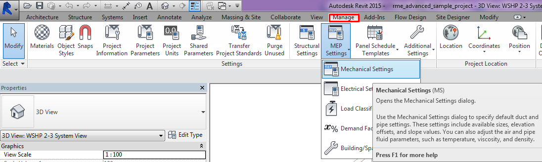
Procedure
Project units
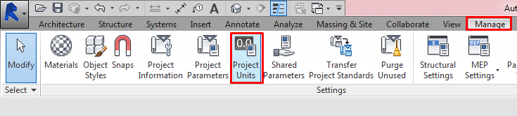
First of all to configure our systems we have to check project units. This can be done by Manage>ProjectUnits or clicking UN Shortcut.
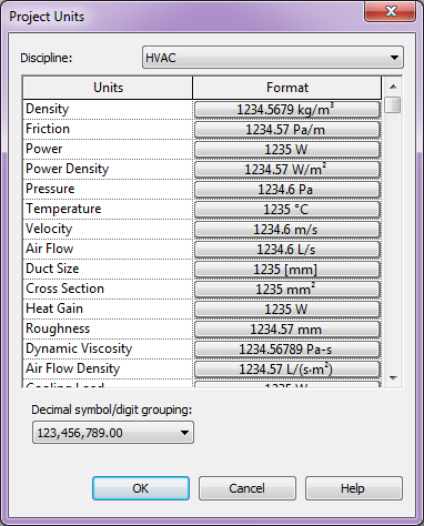
When we are inside we have to check all of our units to fit them to our calculations requirements.
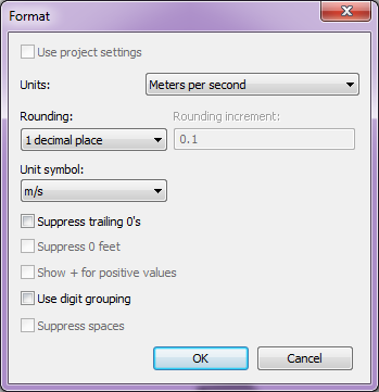
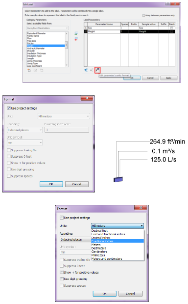
We can use only one unit for each physical property but we can annotate them with another unit, when we are in a Duct/Pipe tag family and we insert a label, we can select the unit it’s going to be shown.
Hidden Line
Once we are inside our mechanical settings dialog box (see above) we found this:
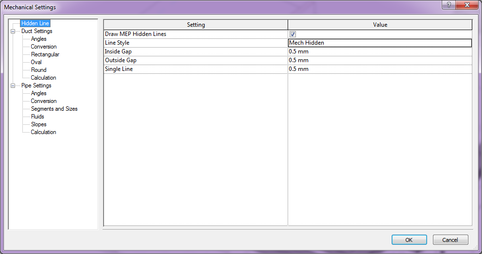
When representing mechanical networks in a floor plan sometimes lines pass one above another, in order to represent these crosses properly in Revit when we are in one of these types of representation we must configure hidden lines.
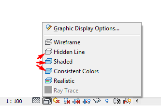
Hidden lines settings are especially useful when we are going to represent our networks in a one-line type of representation (Coarse). We can configure the distance of the gap.
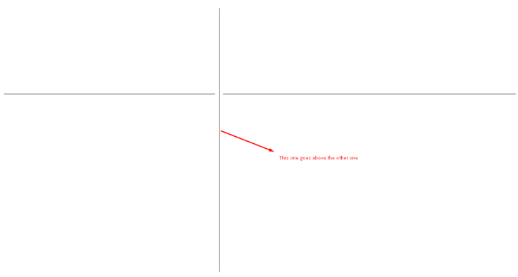
Otherwise it is better to deactivate the Draw MEP Hidden Lines because crosses between Two-line elements are clearly represented.
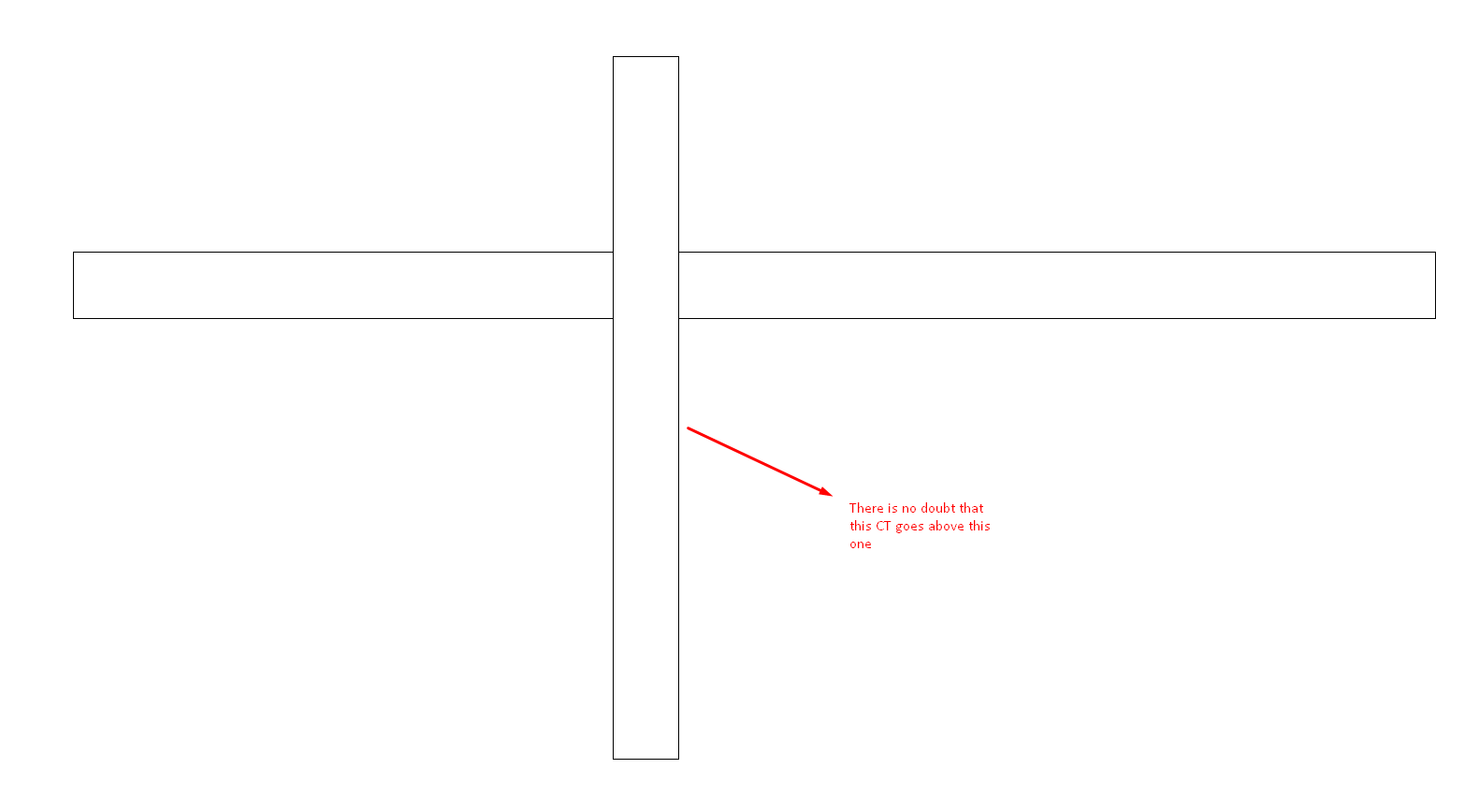
Be careful. You have to pay attention if you are representing your elements within a floor plan or a ceiling plan.
General and Angles
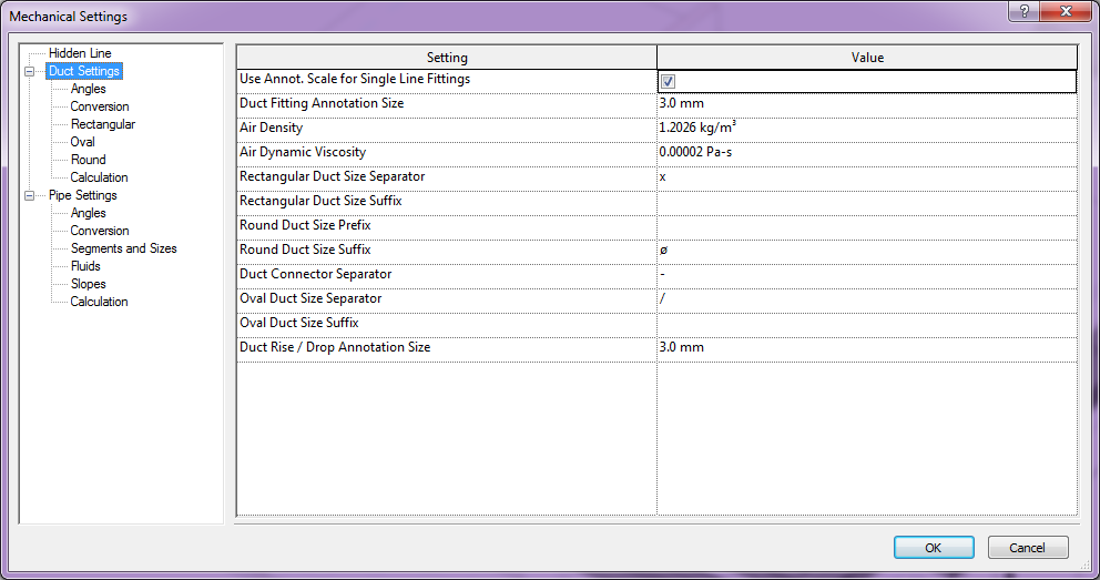
In general mechanical settings we can configure how Revit’s going to express some information from our systems by default. Naming and conventions. Air density and air dynamic viscosity is configured by default, always as shown.
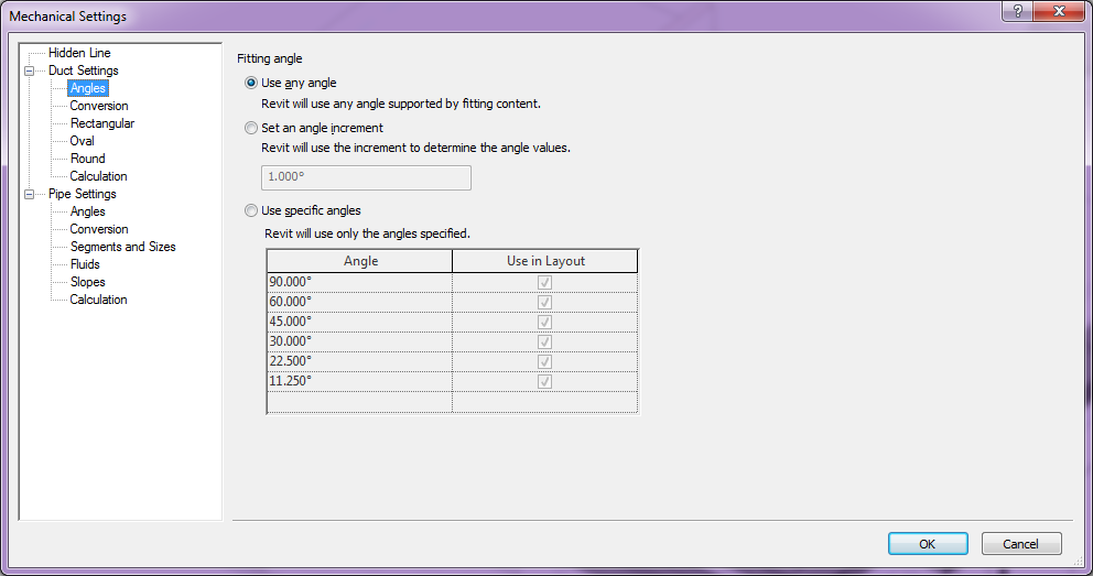
In angles we can configure how Revit is going to create fitting angles when we are modeling. By default we are going to Use any angle. This is because sometimes it could be really frustrating to model some distribution system figures with constraints in angle creation. This decision leaves some angle responsibility in modeler hands, but technically we consider that on site we have versatility enough to achieve almost any angle.
“Set angle increment” option is only available for ducts, this option allows you to take more control over fitting’s angles during modeling, setting an increment to avoid non multiples of it.
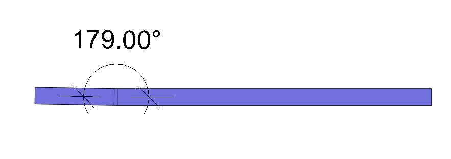
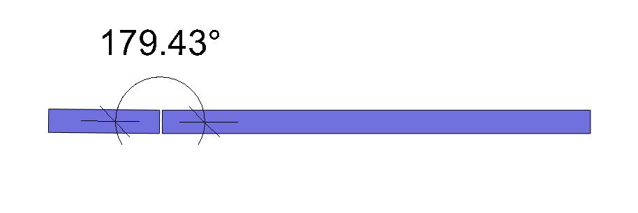
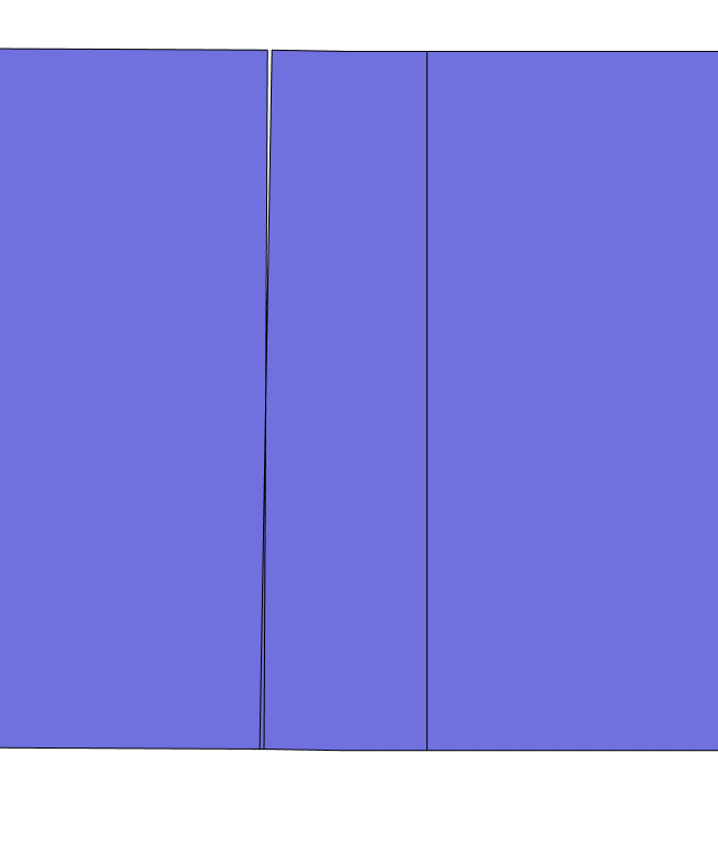
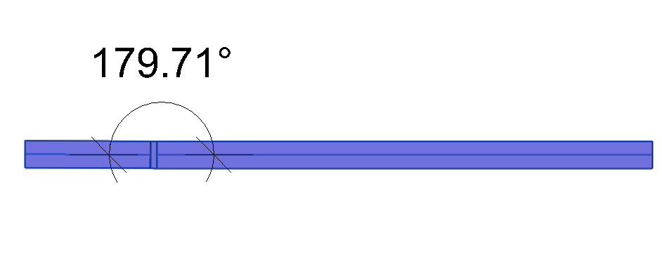
We cannot perform directly fitting angles below 1º, but if we have to, we can rotate our duct in a section or in a 3D properly workplane-setted up, non-recommended action alert!!
Conversion
In this tab is where we define duct/pipe types by system classification, also we can predefine offsets.
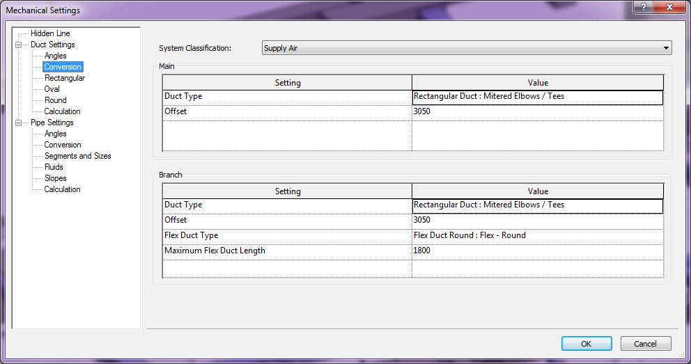
We have 3 primitive system classifications in duct systems:

In piping systems we have 11:

We shouldn’t perform networks mixing 2 system classifications.
2 connectors from different system classification may not be connected by a network. They can but this kind of situation is not useful at all. It is better to connect them to a family with 2 connectors of different system classification in between.
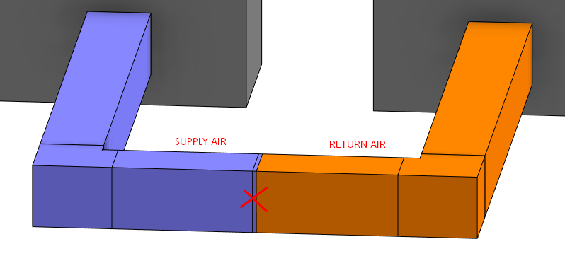
To perform calculations it is important to respect some basic criteria and this is one important rule to follow.
Each system classification has its own parameters, even calculation methods so it’s not a good idea to try to mix them…
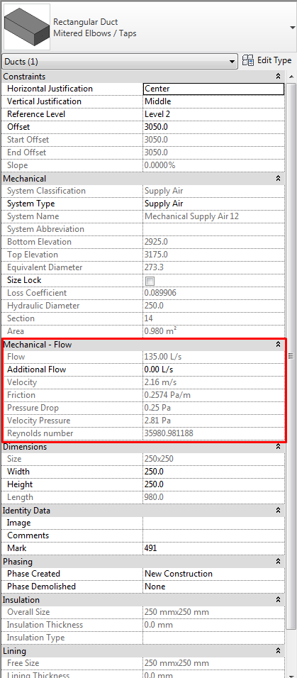
There are some pipe/ducts parameters that are filled dynamically if the branch is connected to an element with a preset flow. These parameters give us a lot of control of our system.
We can choose if our system is in full calculation mode “all” (model slower) or in “none” / “performance” (model faster)
If Calculations are not used for the project, it is recommended to set these at “none” / “performance”

“Flow only” deactivates Static Pressure calculations, and “none” or “performance” deactivates Static Pressure and Flow…
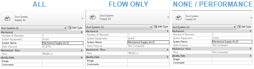
Relationship between system classifications and calculation is listed below.
System Classification | All | Flow Only | Volume Only | None | Performance |
Supply Air |
| ||||
Return Air |
| ||||
Exhaust Air |
| ||||
Domestic Cold Water |
| ||||
Domestic Hot Water |
| ||||
Hydronic Supply |
| ||||
Hydronic Return |
| ||||
Sanitary |
|
| |||
Vent |
|
| |||
Other |
|
| |||
Fire Protection Wet |
|
| |||
Fire Protection Dry |
|
| |||
Fire Protection Pre-Action |
|
| |||
Fire Protection Other |
|
|


Routing preferences
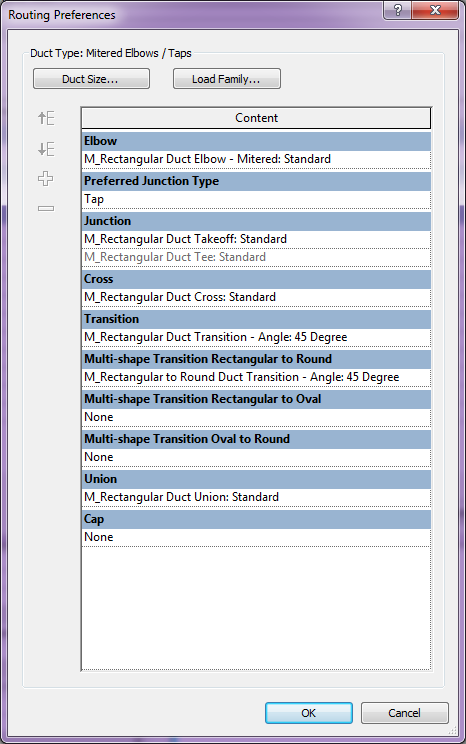
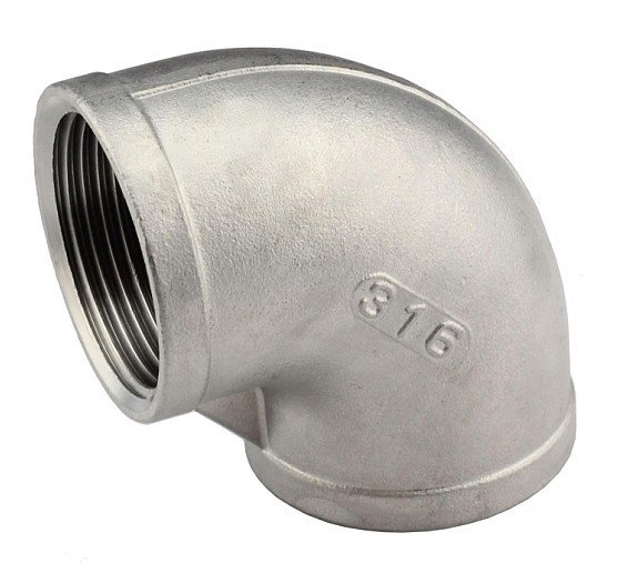
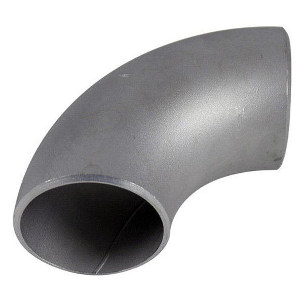
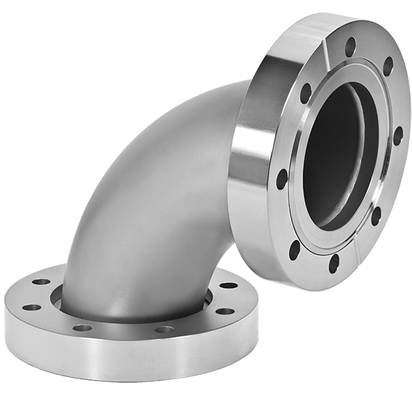
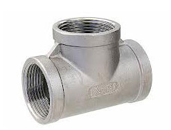
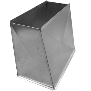
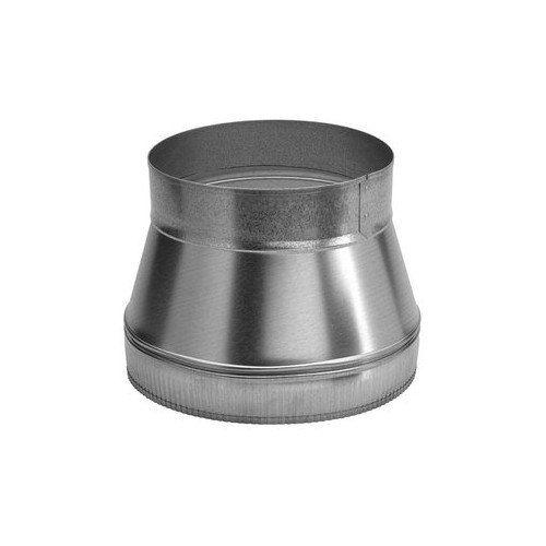
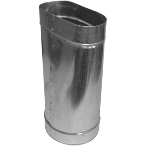
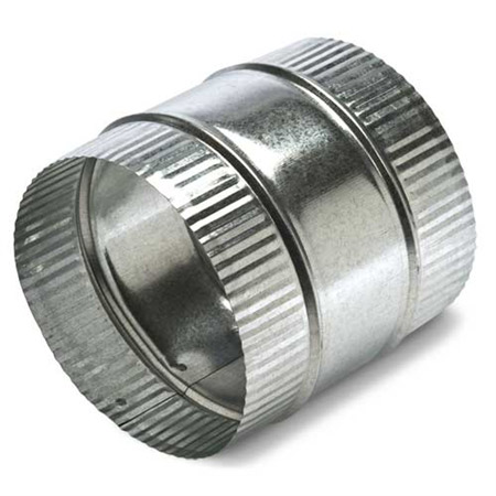
This dialog box gives you options for assigning fitting components to the system family. It’s really important to set up these properly to get the model closer to reality from the POV of engineering.
The routing preference should be set up in the template file for more common Mep systems criterias.
What fitting can you set?
For Pipe Systems:
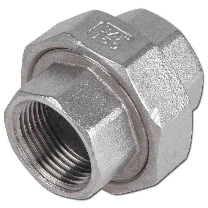
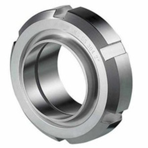
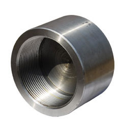
Type of Fitting/Union | Threaded | Welded | Flanged |
Elbow |
| ||
Junction (Tap) | X | X | X |
Junction (Tee) |
| ||
Cross | |||
Transition | |||
Union | |||
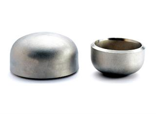
Cap | |||
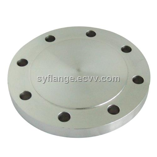
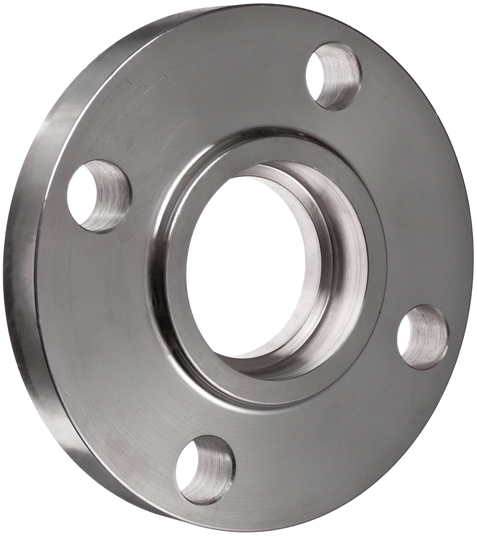
Flange | X | X |
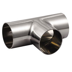
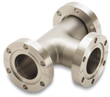
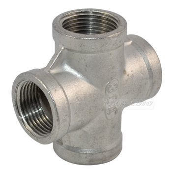
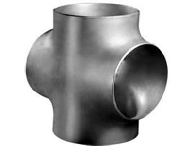
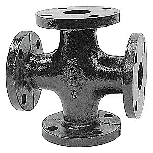
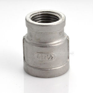
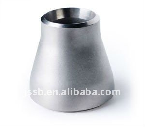
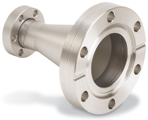
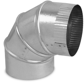
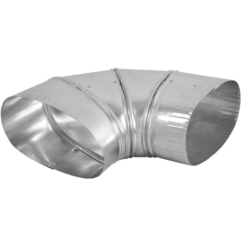
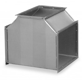
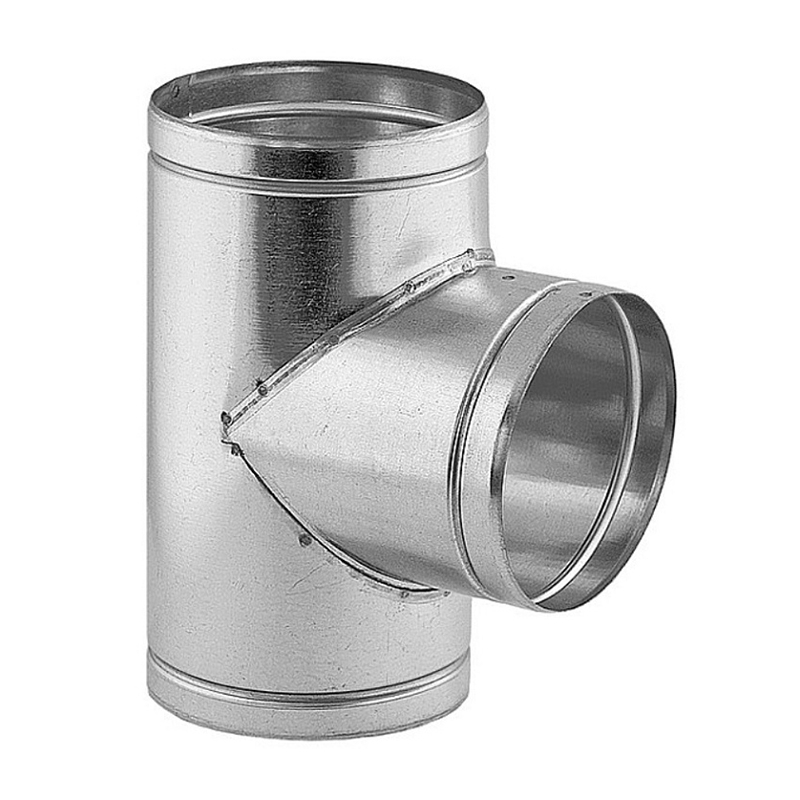
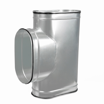
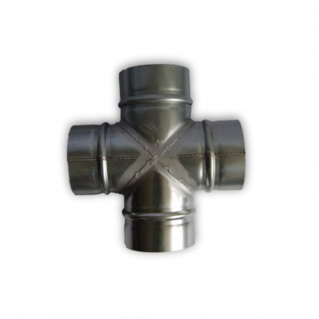
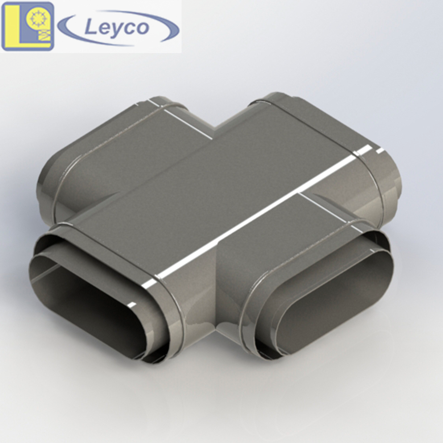
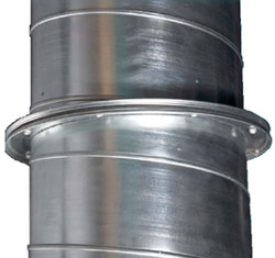
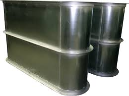
For Duct Systems
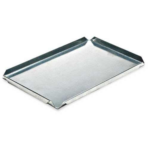
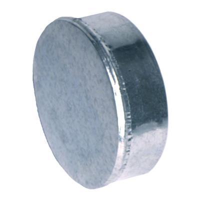
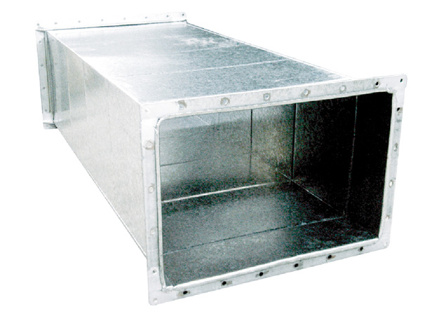
Type of Fitting/Section | Rectangular | Round | Oval |
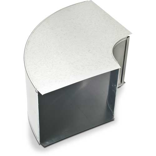
Elbow |
| ||
Junction (Tap) | X | X | X |
Junction (Tee) |
| ||
Cross | |||
Transition | |||
Union | X | X | |
Cap | |||
Flange |
Lookup tables in fittings
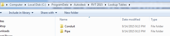
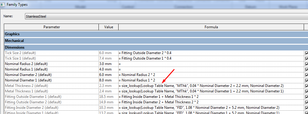
- Lookup tables can be used to define parameter values in an external file. This is beneficial when you have multiple part sizes that are based on a table, but don’t want to create a separate family type for each size.
- Revit provides a text_file_lookup function that can be used to read the necessary values from a comma separated values (.csv) file.
Segments and Sizes (Pipes)
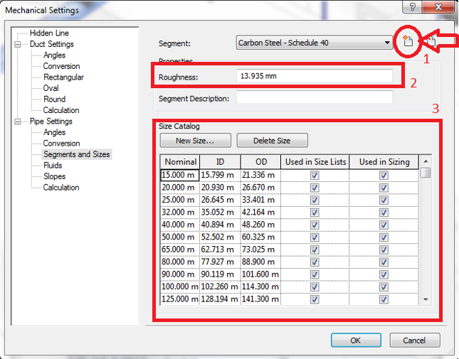
For pipes, in different ways of ducts, we must first define the pipe segment that we want to bring to the project.
- How to create a new pipe segment
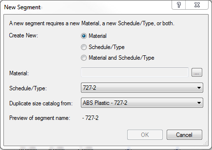
There are three ways to create the segment:
1.- By new Material: Specifying the new Material of the Segment, Selecting an existing schedule type and copying the sizes of another segment (editable by user).
2.- By new Schedule or type segment: Selecting an existing project Material, writing down the new schedule/Type name and copying the sizes of another segment (editable by user).
3.- By new Material or type segment: Creating both new, copying sizes of another segment. (editable by user).
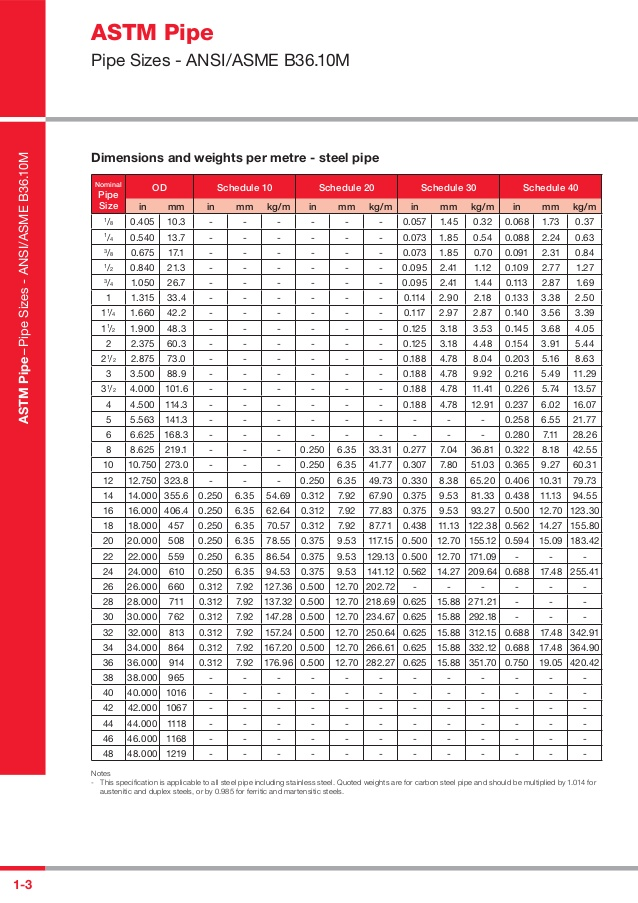
The new pipe schedule name and sizes should have a close relationship with the data provided by manufacturers.
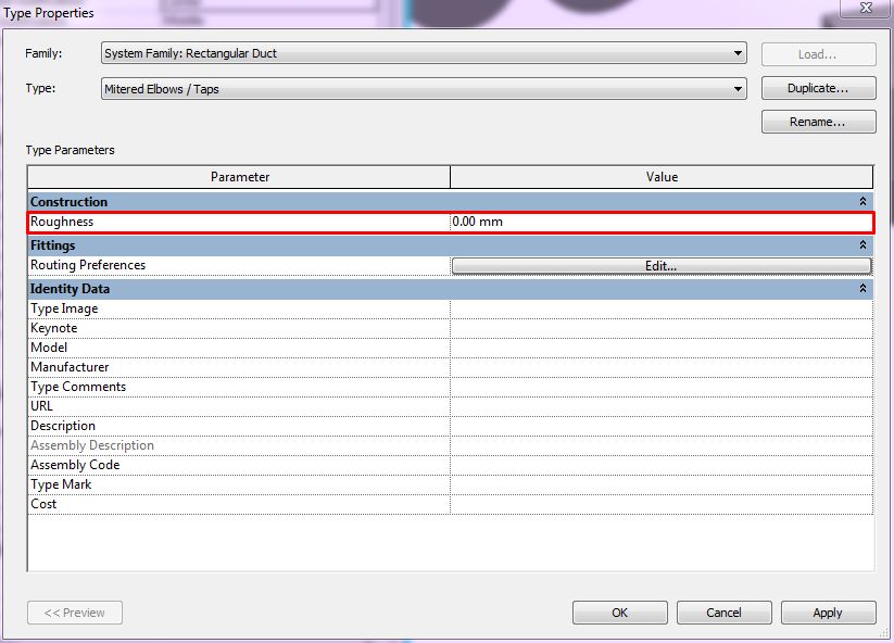
2. Roughness
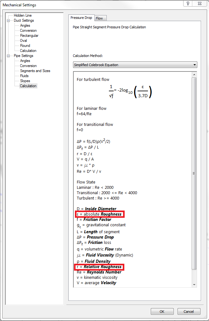
The roughness specification has a direct impact on system for pressure drop calculations
Lower Roughness - Lower Pressure Drop
3. How to create a new Size Catalog.
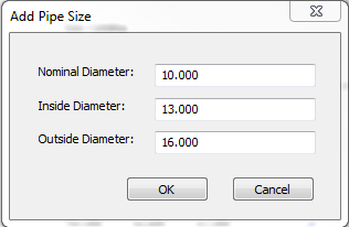
To create a new pipe size, simply specify the three main sizes. It’s important to get the precise Outside Diameter (OD) (related to Nominal Diameter in some materials), and Inside diameter (ID) (related to flow calculation).
Duct Sizes (Rectangular, Oval & Round)
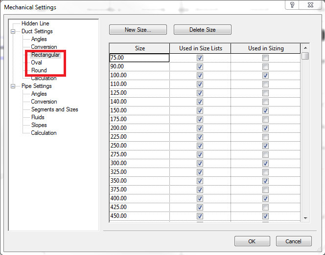
In ducts,the material is defined by the duct type name, whose parameter can specify the material roughness. Inside Mechanical settings we can only specify the sizes used in drawing selection lists and duct layout sizing.
Fluids
In pipe settings we can define what kind of fluids we have in our project by defining a set of temperatures in relationship with dynamic viscosity and density
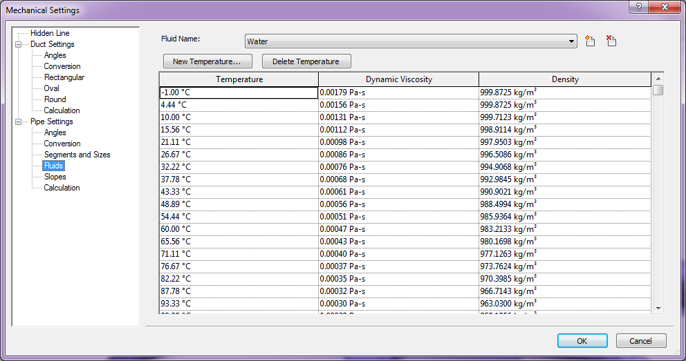
So when you define the pipe system type properties you can choose (if system classification allows you to do so) fluid type and temperature and then dynamic viscosity and fluid density parameters are automatically filled.
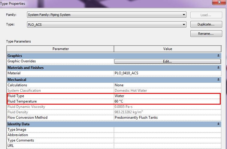
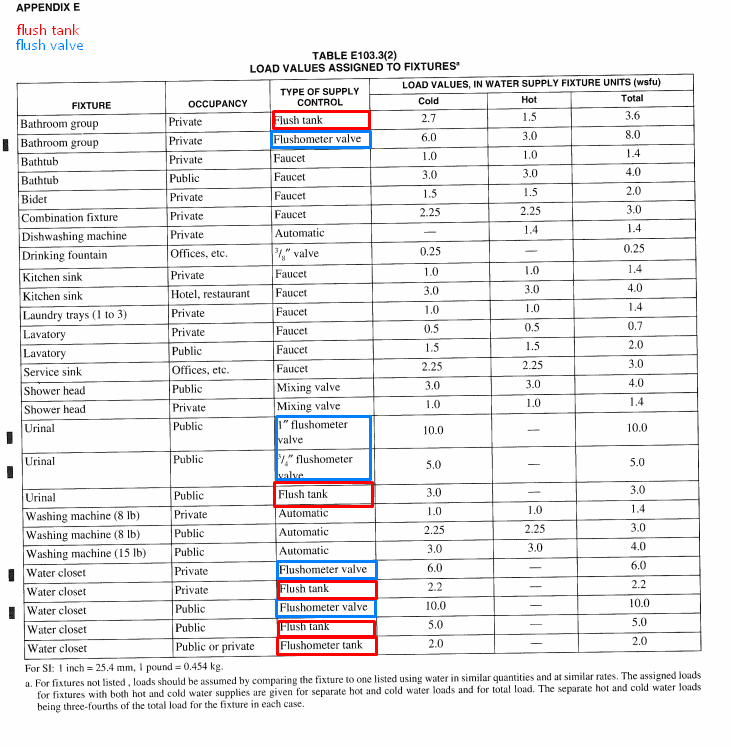
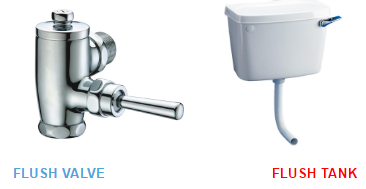
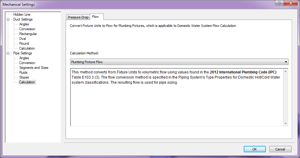
In piping systems type properties sometimes we can see a Flow Conversion Method parameter. It has to be defined in some system classification types. Flush tanks or flush valves, this is related to International Plumbing Code (IPC). Pg:132 and to simultaneity methods applied too.
Slopes
Slopes are crucial in sanitary systems. This property is truly useful because when we are modeling a pipe in a floor plan view I really don’t control my Z axis deviation.
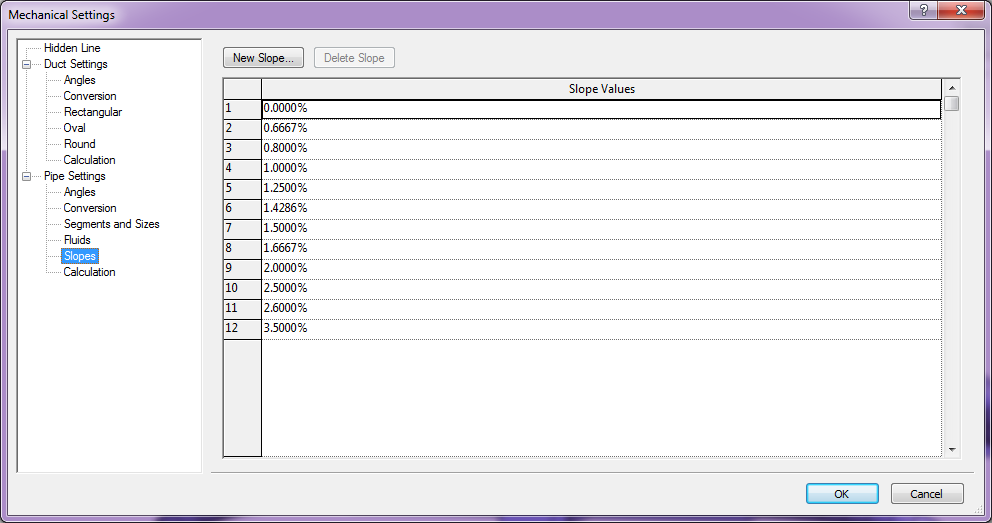

This dialog box corresponds to a pipe modeling action.
Revit way is to select a slope and a slope direction (up or down) and start modeling like in 2D, we can activate a slope tooltip which dynamically shows my start and end offset and my slope when drawing.
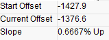
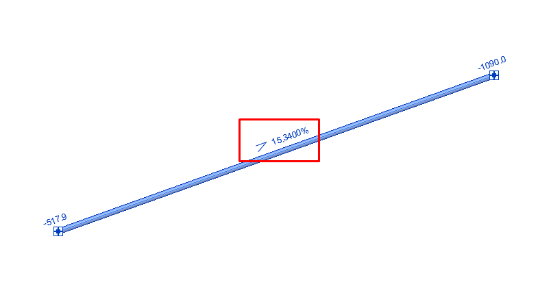
We can also modify our slopes with slope value that appears over a pipe when selected.
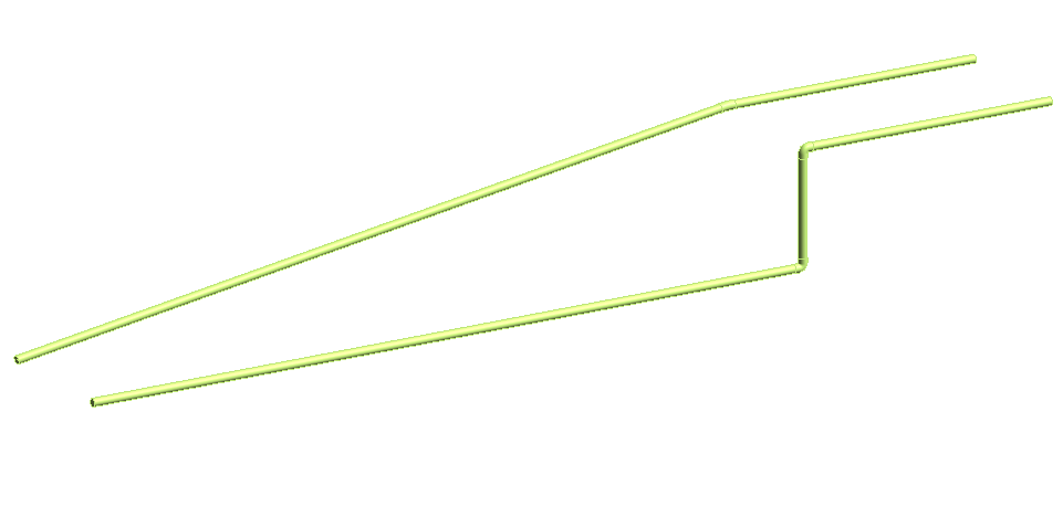
If we have two pipes with different offset values, connections between them in a floor plan modeling action can be done by default with vertical pipes or sloped ones.
Also when we’re modeling a new duct/pipe we can select if we want to inherit size or an offset from the pipe/duct I’m going to start. This is really useful, especially in sloped systems, because usually you want to continue your network and with these tools you don’t have to remember the size or end offset of the previous segment.
Placeholder modeling
There is an option in which we can start modeling lines and then translate them into real pipes and ducts, this is called Placeholder modeling and we can find it in the systems tab:

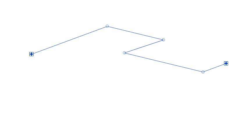
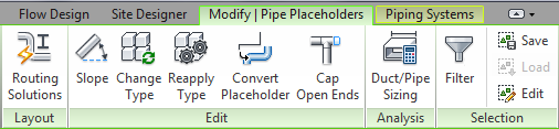
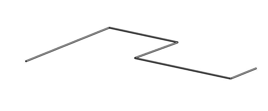
It’s not really useful because, when modeling, segment’s sizes are necessary to choose the correct path.
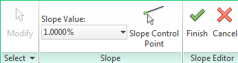
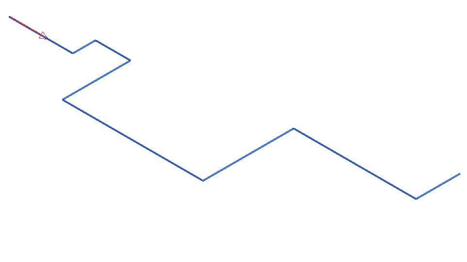
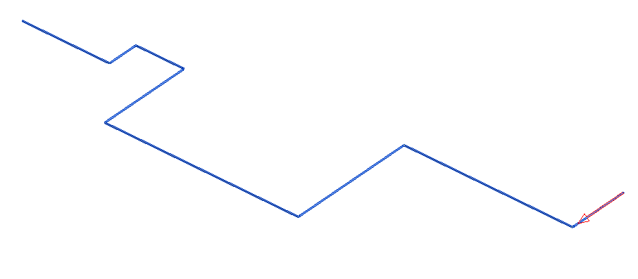
The slope tool is here to help us deal with slopes. You select a bunch of segments and it will change their slope to another. You can swap the start point where the slope is applied by clicking the slope control point.
It’s better to model slopes when we are modeling our pipes, but this tool can be useful in order to avoid remodeling failed sloped systems
Connectors
Connectors are special elements that appear only in family creation environments. There are 5 types and many subtypes by system classification, but here we are going to see only duct and pipe connectors.
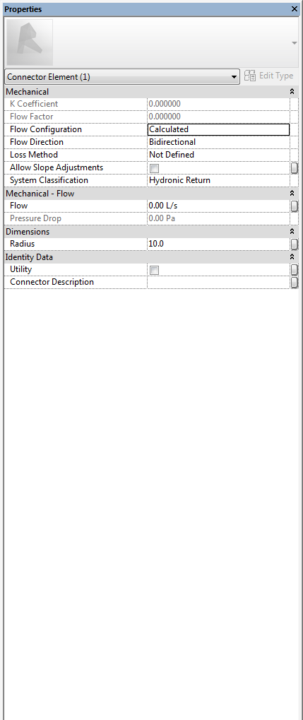
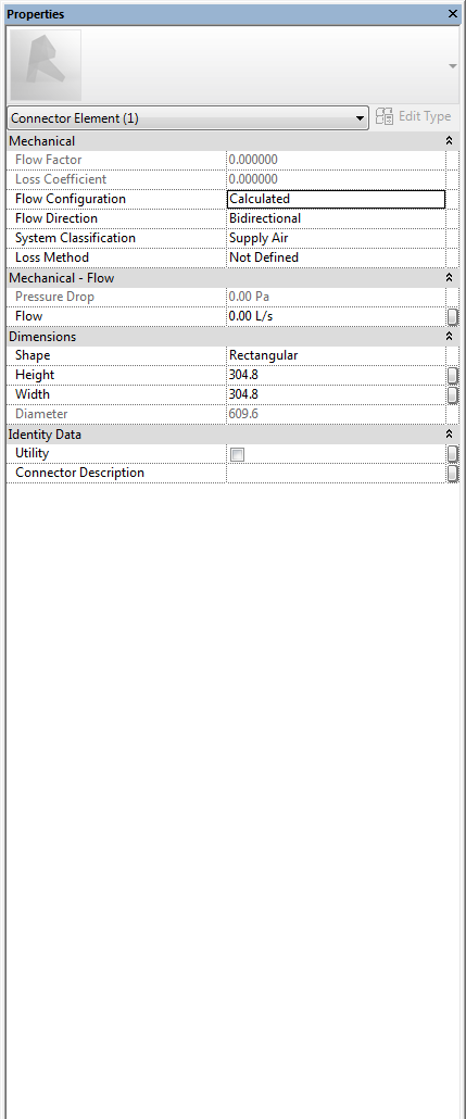
Here we can see the pipe connector and duct connector’s properties. Let’s go through them:
System classification:
This is the most important parameter in a connector's properties because it radically changes the appearance of other parameters.
There are 2 special values here, Global and Fitting. We select global when in this connector we don’t expect any kind of system in particular. And fitting is also a polyvalent system classification.
Flow configuration:
Preset, system or calculated. This depends on what we want to calculate, but if we want to calculate any value in the system we have to go to Calculate-Preset or System-Preset schemas.
In Preset we have to configure the flow parameter before the system performs the calculation. In calculation we only have to wait for results. Also in the system, but in the system we have to define the flow factor.
In piping systems we can also select Fixture units. This kind of configuration works like the preset one, but when we are working with fixture units we are taking care of simultaneity.
Flow factor:
When we select a system in flow configuration we can select a flow factor for my connector. This helps revit when we have parallel elements like pumps in applying a percentage of the main flow to each branch.
Flow direction:
With this parameter we indicate the direction of the fluid, we can choose between IN, OUT or Bidirectional. This is truly important and must be setted up accordingly in real flow directions if we want everything working all right.
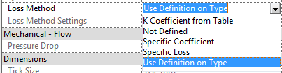
Loss method:
This parameter is related to how losses are calculated. There are many loss methods from specific losses to specific coefficients. These parameters are edited in the project environment By element or type parameters.
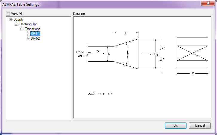
K/Loss coefficient:
Most efficient way to select a loss for our elements is to pick coefficients from ASHRAE tables which are placed inside Revit. We can select what table revit’s going to use to calculate the loss.
When we cannot use this option we have to fill the coefficient parameter or the specific loss by hand.
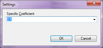

In pipe connectors ASHRAE tables are substituted with K coefficient tables.
Pressure Drop:
When we select as the loss method “Specific loss” we can put the pressure drop here as a default value. When we select a coefficient method we cannot fill this parameter because it’s going to be calculated
Allow slope adjustments:
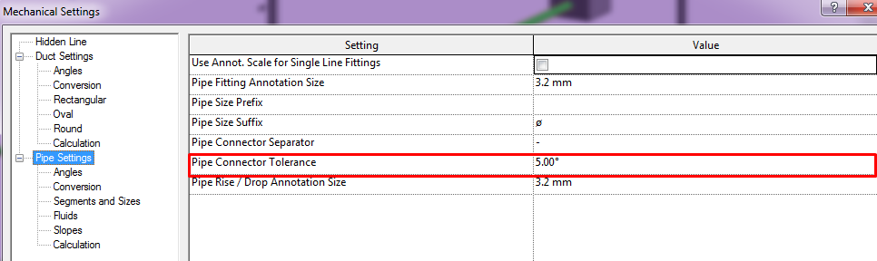
This is a boolean parameter, when it is checked we’re allowing our family to connect segments with a certain slope. Angle tolerance for this adjustment can be found in mechanical settings pipe general settings
Flow:
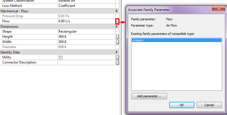
Flow parameter may be the most important parameter in mechanical connectors. We can match this parameter to a shared instance flow parameter to have it for checking in the project. If we have selected a system/calculated it’s going to be filled automatically when the system will be properly connected.
Dimensions:
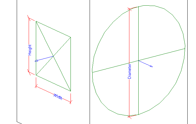
In the dimensions parameter group we can define our shape in ducts (oval, round or rectangular) and the Height, Width and Diameter. We can match these parameters to instance or type parameters. Instances will adapt to a different sized duct input type don’t.
System Inspector
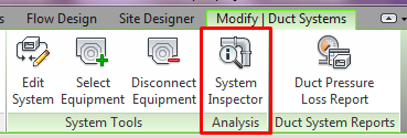
When systems are correctly configured and connected then we can use this wonderful tool for flow and visualization.
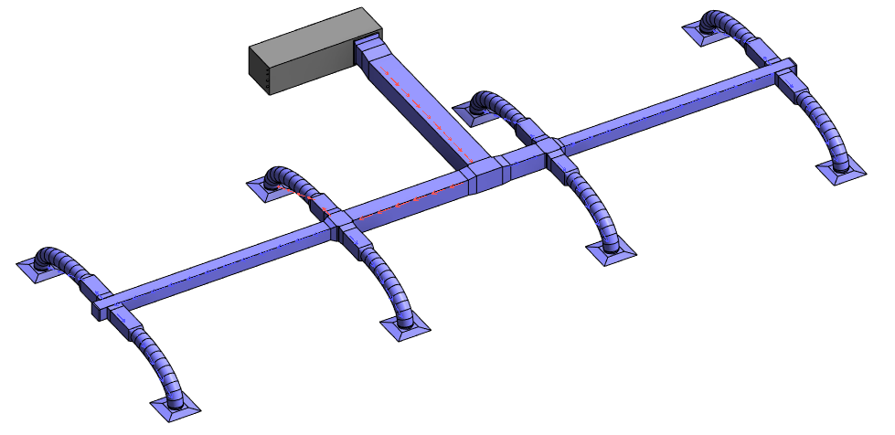
We can see in red the critical path, this can help us in error detection. If the critical path doesn't go to the further element we can check pressure losses to find the failure.
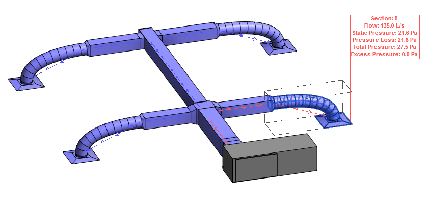
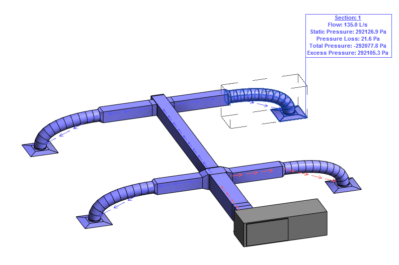
Sometimes there are aberrant results in networks or in values that we have to check too.
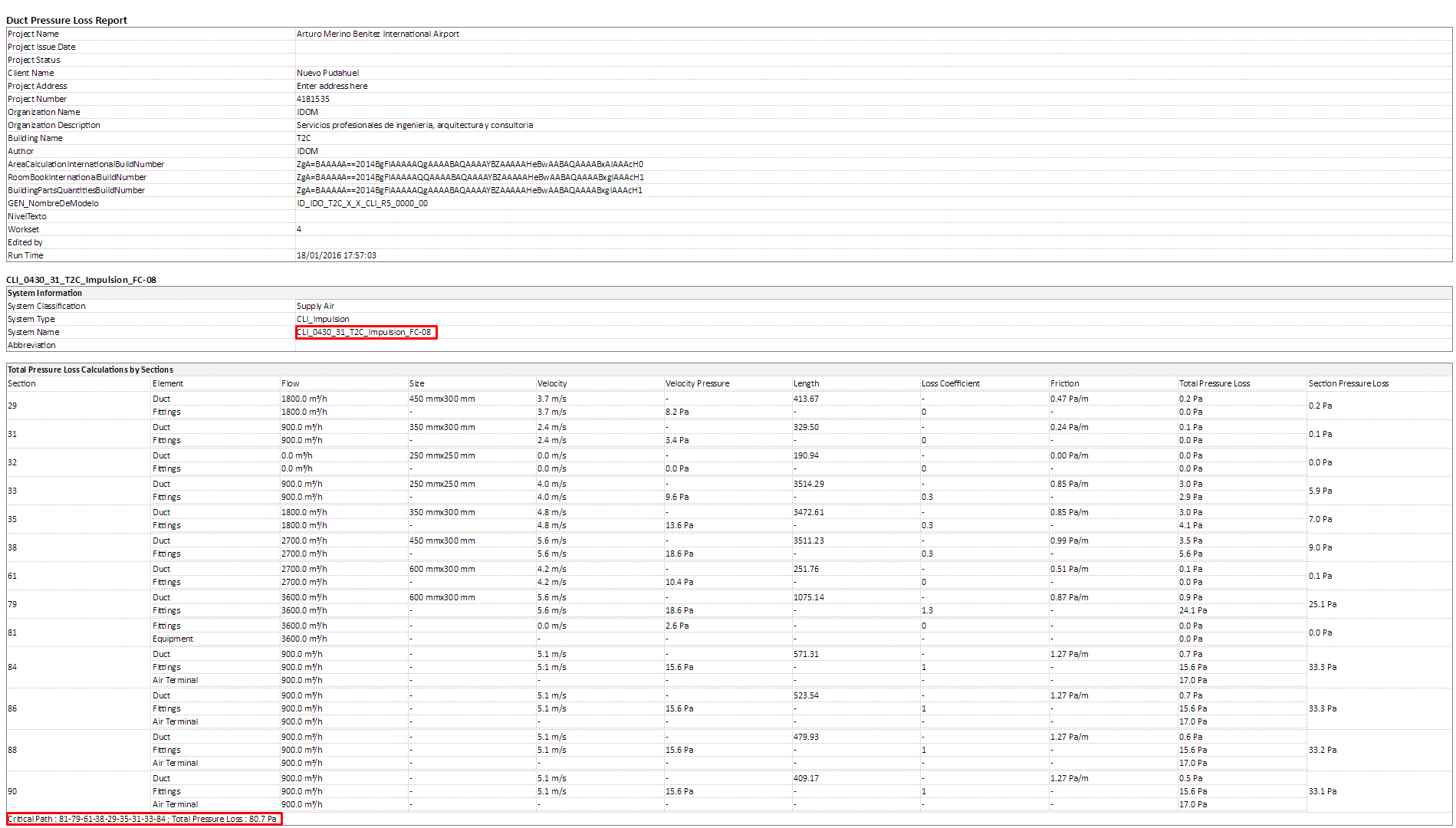
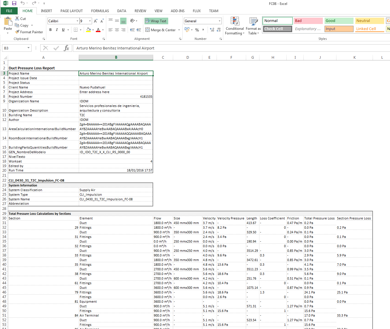
Pressure Loss Reports
When we are done with our configuration we can export calculations in an .html format that we can open in an excel spreadsheet for editing purposes.
Reports are generated by system, so it’s crucial to have our systems properly named and ordered.
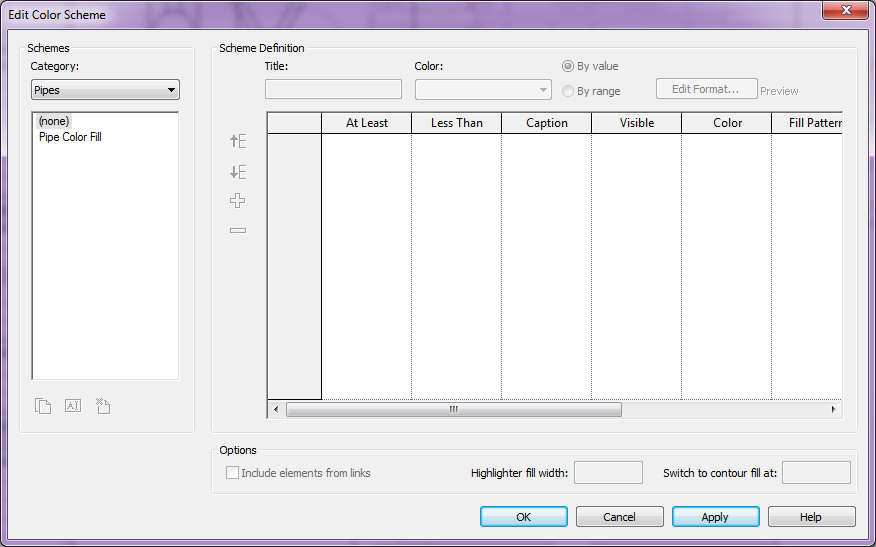
System Color Schemes
Users can make system color schemes in floor plans for duct systems or pipe systems by specific parameters to seek errors. This kind of powerful data visualization techniques gives us more and more control over our active system design.

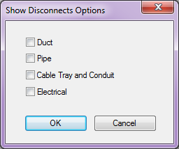
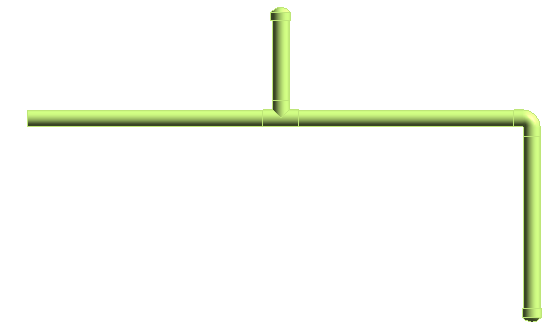
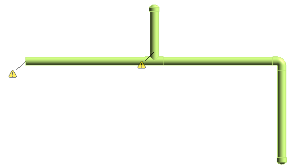
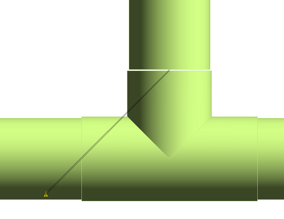
Show disconnects
Disconnected elements sometimes are hard to find, but that’s why the Show disconnects tool exists. Always on!

Check systems
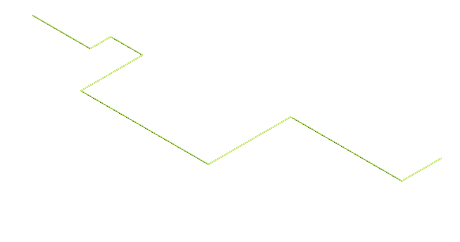
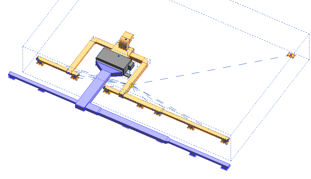
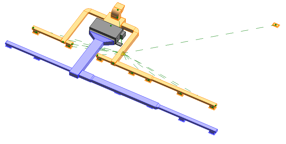
Check systems is necessary when we are trying to detect unconnected elements in our system. When everything is well connected nothing happens.
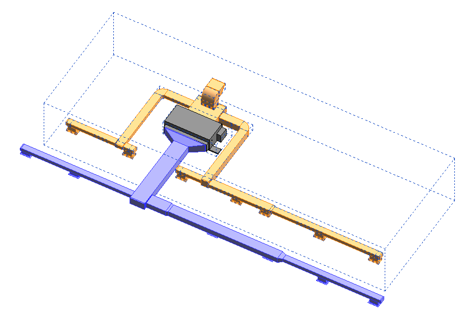
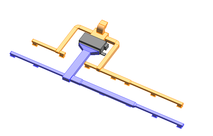
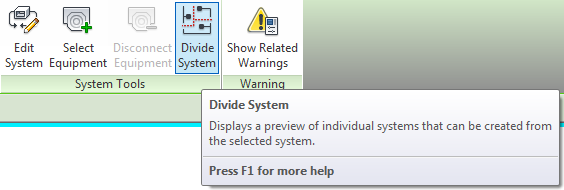
When any element is unconnected some green dashed lines appear. Here we have two options: we can connect it properly or divide the system.
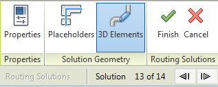
Routing Solutions

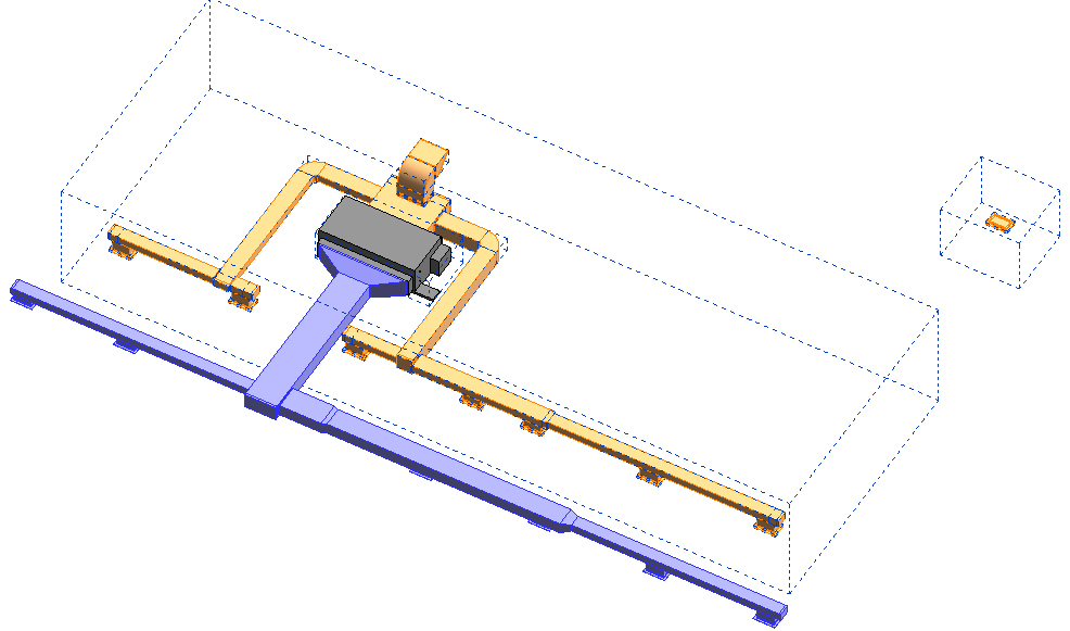
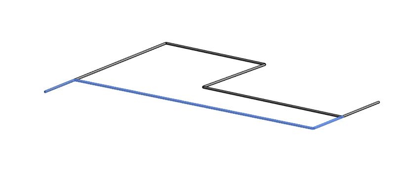
If you select a pipe network you can use this tool and Revit is going to propose some alternate distributions from your start point to your end point. Some proposals are really interesting but usually 80% are rubbish.
Justify
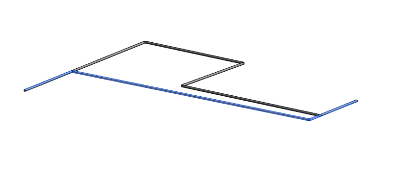
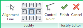
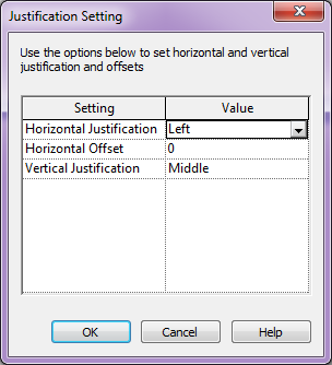
Sometimes we have spatial constraints and we have to justify our pipe/duct segments to one specific edge or point. Revit allows us to do this with the justify tool. When modeling we can choose where we want to justify our segments.
Fittings must allow us to do such a thing obviously. We can perform justifications before or after modeling.



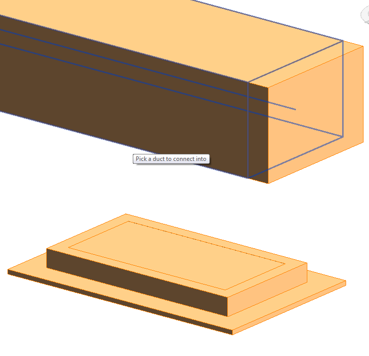
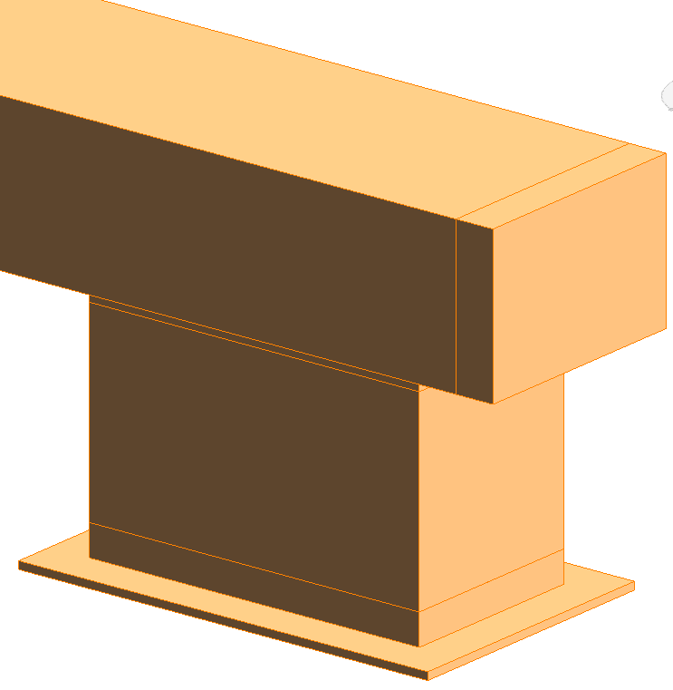
Connect into
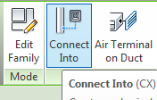
We can select a plumbing fixture, an air terminal or a mechanical equipment and select “Connect Into” a segment which sometimes doesn’t work properly but when it works it’s fantastic!
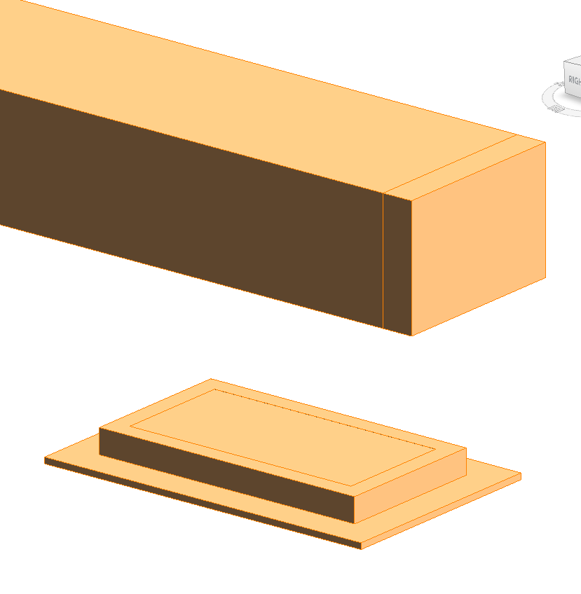
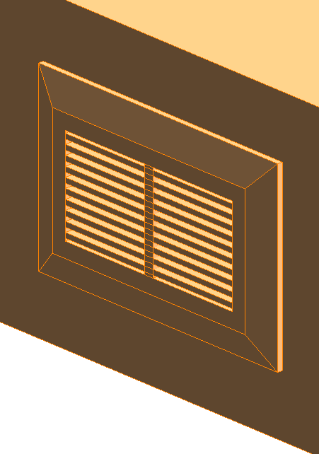
When we want to create an air terminal on a duct we have to select the air terminal “On Duct” before we create it acts like a hosted element.
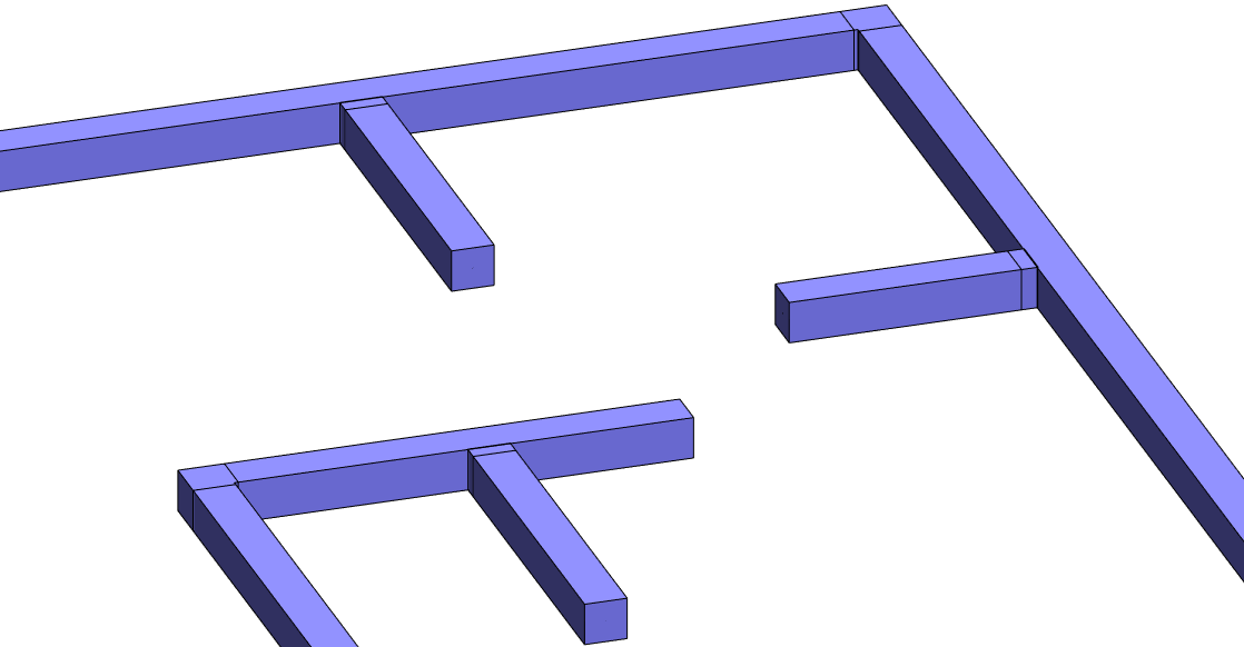
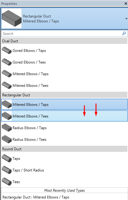
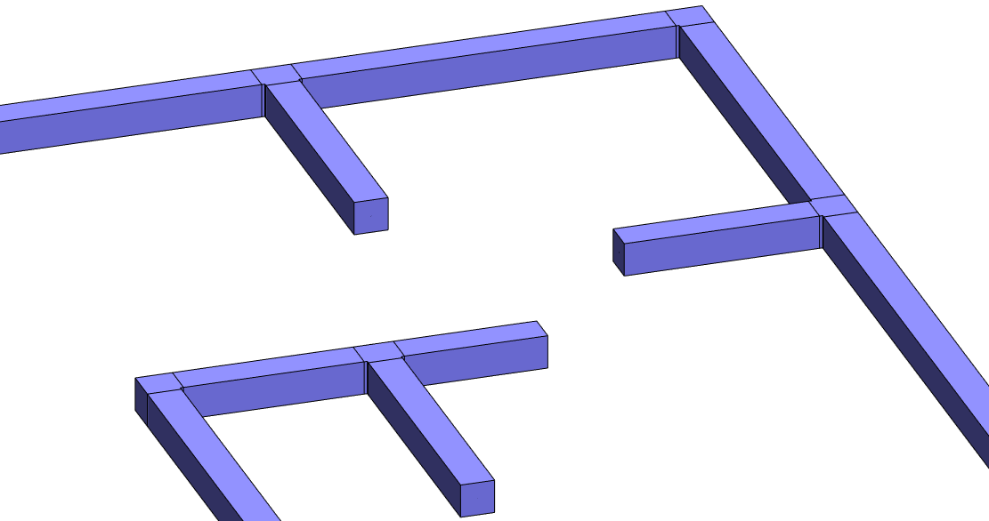
Change Type

We can select an entire network, or a branch and change the type for every single element inside it and attending to its routing preferences, in this case from a tap to a tee type:
Reapply Type

Also if we have made changes in my type configuration and I want to propagate the changes I can do it with the Reapply type tool. In this case from square elbows to rounded ones:
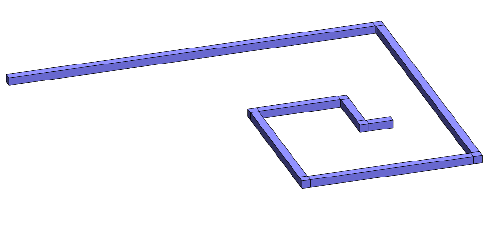
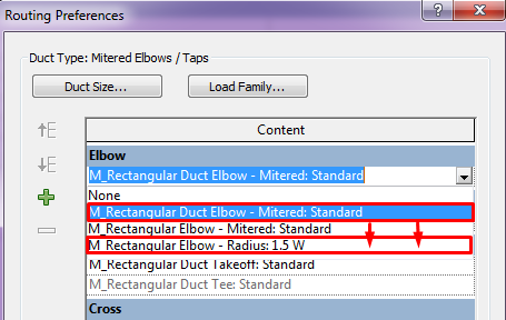
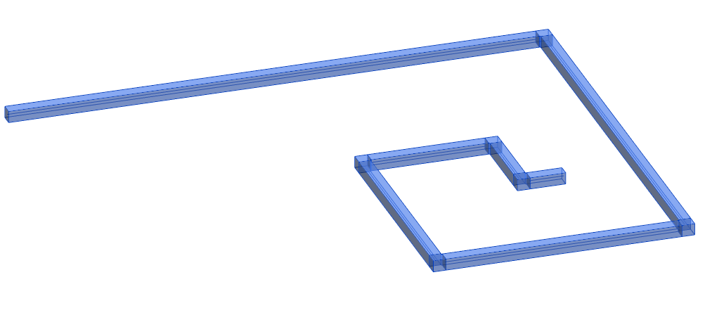
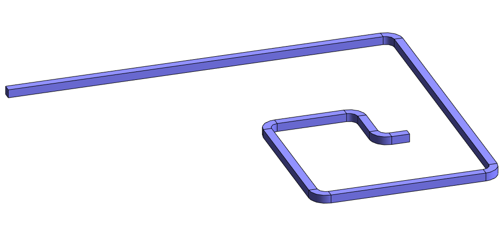
Be careful if your new fittings are bigger than the previous ones, especially if you have your system so tight, this aspect can throw some warnings… You have to be very careful about the spaces between elements in the network.
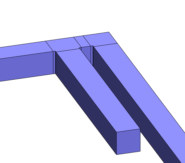
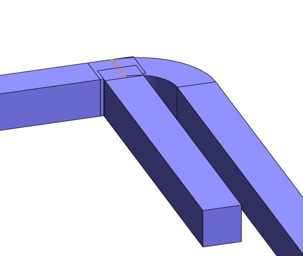
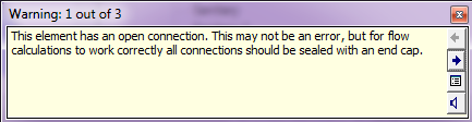
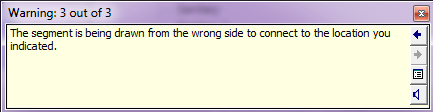
If this happens there’s no option. We have to change fitting types manually...
Cap Open Ends

This option allows you to place a cap at the end of a pipe, or pipes, this tool is really useful and we’re going to use it recurrently so it is best to have a shortcut CA for example. Remember, to access keyboard shortcuts press KS.
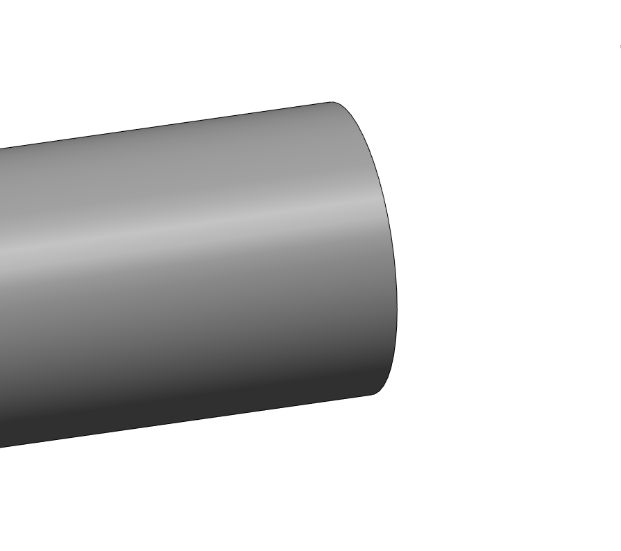
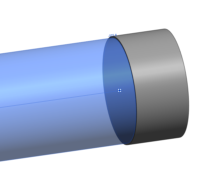
Be careful because it puts a cap in every single open end it finds.
Insulation
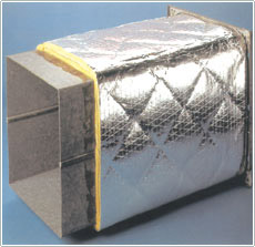

Insulation is placed for temperature control. It consists of a wrapping system outside the duct. Adding insulation is a really quick task. Normally it is performed when everything is correctly connected. This is because we want to do it all at once. But it is necessary to have it in mind when modeling, otherwise we’re going to have space problems later.
It’s best to have them with the transparency property activated.
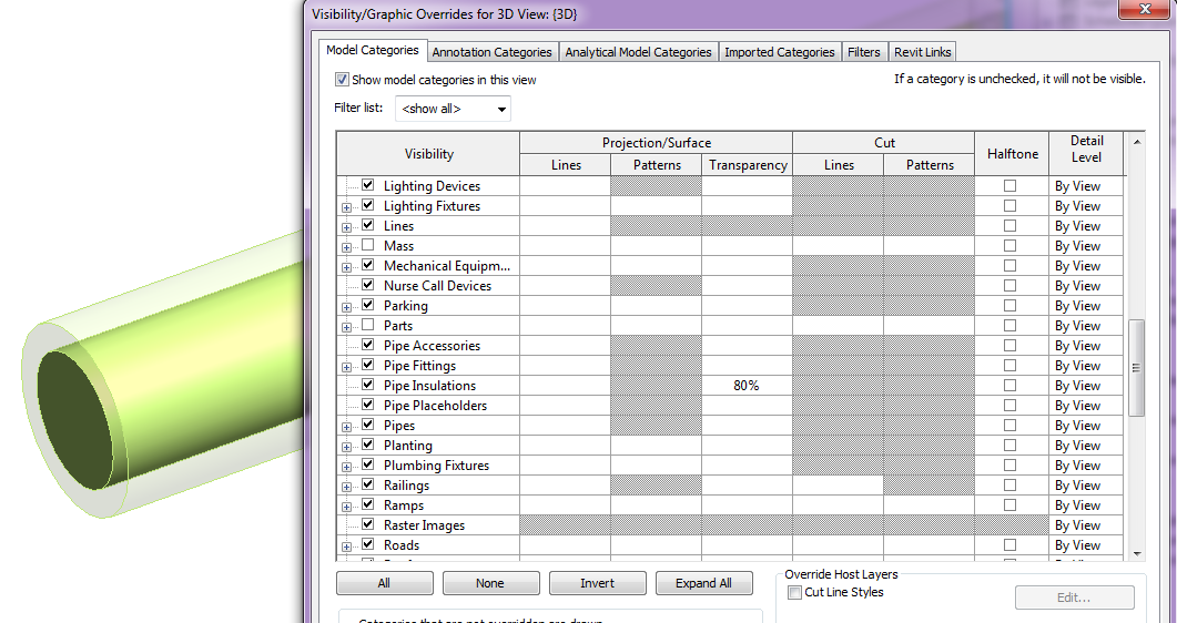
If we have placed our insulation in an incorrect workset we have to insert them into a group, change the workset of the group, and then explode it. There’s no other way to do that.
Lining
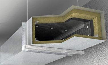
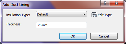
Lining is placed for noise control. It consists of a wrapping system inside the duct. Usually we control noise control with air velocity but sometimes we have limitations in sizing and we must place a lining. Like insulation this must be a finish task
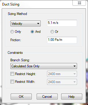
Duct/Pipe Sizing
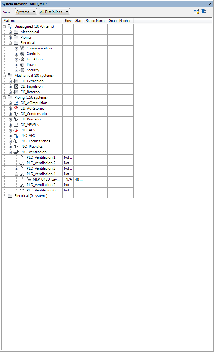
System Browser
System Browser (F9) is where we are going to manage our systems, where we are going to select them and also where we are going to check if everything is ok with them. What calculations is the model performing and how is it classified?
It is classified first of all by unassigned and assigned elements, second, by Mechanical/Electrical/Piping categories, then by system classifications, then by system instances and then by fixture instances.
We can watch spaces and HVAC zones classification too.
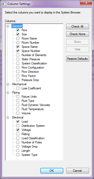
If we want to select what parameters are shown in SB we can do it by clicking the column options icon which is placed up and right in the dialog box.

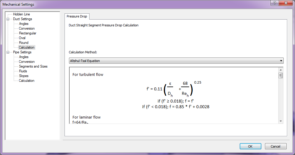
Duct Calculations
We can select our duct friction calculation method here, by default we have:
Colebrook
Haaland
Altshul-Tsal (note that in transitional flows it is 0)
Also you have to take care of Duct roughness to perform calculations properly.
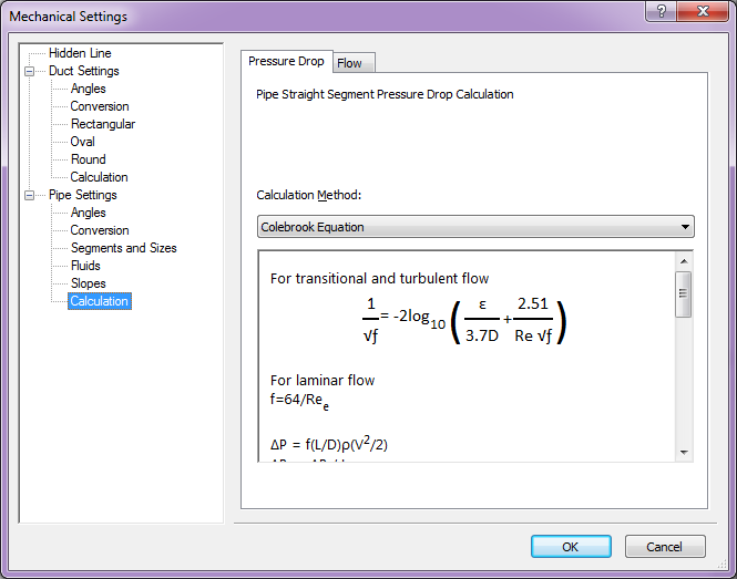
Pipe Calculations
We can select our pipe friction calculation method here, by default we have:
Colebrook
Haaland
Altshul-Tsal (note that in transitional flows it is 0)
In the flow tab we can see from what table Revit converts Fixtures Units to flow.
Tips & Tricks
- Try to configure general settings once. Do a template file.
- Be tidy in Mechanical Systems modeling. They are rigid, so if you detect a setting failure, don’t procrastinate.
Bottom-line
Canonical workflow in mechanical projects is what follows:
- Create piping/duct systems regarding system types.
- Create materials by systems to assign colors to them.
- Create Pipe/Duct types regarding materials and shapes.
- Set up Pipe/Duct sizes, slopes & fluids (piping) by type.
- Define Routing preferences by selecting and loading fitting families.
- Model equipment families and accessories, be careful with connectors’ parameters.
- Detect geometric relationships in systems’ routes, symmetries, copies, arrays...
- Model systems’ distributions.
- Inspect systems.
- Sizing.
- Color Schemes.
- Documentation.
Associated Files
- 30035_MOD_BIMMasterplan_MEC_Training_Settings_01 (Template)
I like your explanations. Particularly on duct pressure calculations. I am beginner in Revit duct cslculatons. I am struggling in some error areas. Can you help me.