

Revit Architecture
Best Practices
Revit Architecture - Best practices
Objectives
- To understand the best techniques to model Architecture in Revit.
Prerequisites
- The user is able to use Revit files.
- The user has basic skills in BIM modelling with Revit, and understands the terminology.
Description
Revit has proven to be powerful when modelling, quantifying and planning architecture, but it’s key to manage our models properly, in order to keep them clean, organized, fluent and weight optimized. This document explains key tips to achieve so.
Procedure
Project management
People and documents
A Project BIM Coordinator shall be appointed for every project.
A Project BIM Strategy shall be put in place that identifies key project tasks, outputs and model configuration.
BIM Project Reviews should be agreed and take place regularly to ensure model integrity and project workflow is maintained.
Develop clear guidelines for internal and external collaborative working which maintain the integrity of electronic data.
Model management
Do not over model. Understand and clearly document what needs to be modelled and to which level of detail.
Subdivide models between disciplines, and within single disciplines avoid file sizes becoming over ~150MB.
All changes to the model shall be carried out as 3D modifications, rather than 2D “patches” to maintain the integrity of the model.
Outstanding warnings shall be reviewed regularly and important issues resolved.
The Central file shall never be opened. It should be recreated at regular intervals in order to eliminate redundant data retention.
A drawing shall contain design information solely for the purpose of the intended use of the drawing. Do not over model again. It is a waste of time and money.
To maximise efficiency a policy of minimum detailing without compromising quality and integrity shall be adopted.
Numbers of drawings should be kept to an absolute minimum and organised in a logical manner.
Project worksharing
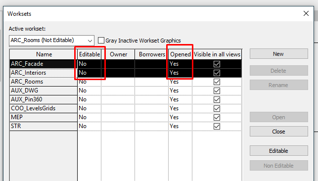
When working on a collaborative network, new local models should be created every morning by every member of the group. When creating a new local, we should not take Worksets as owners, as it generates issues of ownership. Instead, we should just open them, so Revit will automatically make us borrowers of them.
It’s encouraged to establish a member of the team who executes 'Compact Central Model' and “audit”on first Sync of the week.
Only one person in each team needs to recreate the central model, but everybody needs to make new local files once the model has been made.
Attempt to keep project team workstation specifications equivalent. A dramatically weaker machine specification used by a single team member can reduce overall project performance.
“Sync with Central” operations can be accelerated by a preceding “Reload Latest” command.
Switch to the default starting view and close all other views before synchronising. This can make it much quicker.
When making significant changes to a project (for example, moving a level or making major geometry changes) it is strongly recommended that you perform these operations when no other users are working on the file and they have relinquished all elements. Then have user make new local files.
Place Revit links into separate worksets so users can easily see which links they have opened at any given time. As more information gets added to the model, it is important to keep the model well-structured by breaking up the model into appropriate “bite-sized” worksets. A good practice is to create a 3D view for each workset and name it properly. Set the visibility graphics for each 3D workset view to isolate the workset. This will provide a convenient way to visually check what is in a workset and to identify items placed in a wrong workset. There is also a tool that color the elements by worksets. It could be helpful to control the worksets.
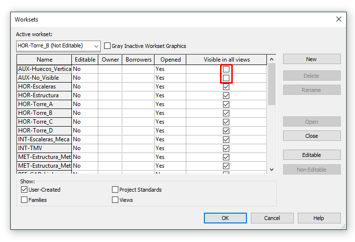
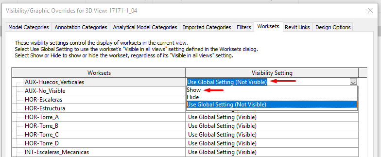
Some elements of the project might not be necessary to be seen in most views (auxiliar elements, masses that give place to other geometries, etc.) in such cases, it’s recommended to create a workset for such elements and disable its visualization by default:
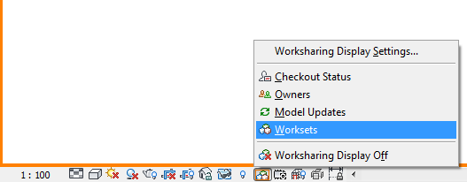
If necessary, the visualization of such elements can be enabled in the settings of a certain view:
Project consistency
Follow these guidelines to ensure you end up with a healthy and well coordinated project.
Images
Large raster images, such as logos scaled down to fit into title blocks, will still retain the original file size. Consider creating a smaller, simplified image for import into Revit.
Warnings review
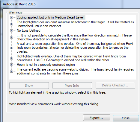
Models should be kept free from as many warnings as possible. Warnings should be reviewed regularly so that the model does not end with a huge warning-report that is impossible to deal with. If models are not properly maintained, it will affect model performance, and error will be carried around to the model life-end.
Few tips depending on the type of warning:
- Some of them could be ignored as “duplicated marks”.
- Warnings that should be specially taken care of are those related to Areas, Rooms, Spaces, and Joined elements.
- Try to limit the use of joining geometry. This will help keep “Can’t keep joined” errors to a minimum when moving objects.
- Elements that are slightly off-axis should be reviewed and corrected. They should only be left off axis if the project design is in fact intended to do so. They can happen because they have been modeled following a Cad drawing.
- Delete not placed rooms in the schedule.
- Do not overlap room boundaries and walls. Considering that Room-related warnings are one of the more harmful for models, they have to be taken very seriously, or they will end in bad model performance.
Groups
Groups are heavier than families. You can use an array to copy and associate objects together. However, after the array is complete, you can ungroup the arrayed objects to increase performance by removing the parametric associations of the copied objects. You can also clear the “Copy and Associate” checkbox when creating the array.
In case you use groups, after delete them, you should purge groups or delete them in the project browser. Ungroup is not enough.
Don't put datum objects in your group. You can't manage the extents of the datum objects unless you're in Edit Group mode, which can create conflicts elsewhere in your project.
Don't nest groups. Although nesting can save time in some situations they can also restrict too much modelling. You can't get to all the features and functionality of Revit when you're in Edit Group mode. It’s also common to have fatal errors while modifying a multiple group.
Always keep your hosted elements and hosts together. For example, do not group doors and windows without the walls that are hosting them. If any of the windows in a group become unhosted from walls and then deleted, this will delete the respective windows in all other group instances-even if they are properly hosted.
Don't use attached relationships in groups. If you manipulate the datum or attached host and the relationship creates inconsistent conditions among the instances of the group, you'll see a warning asking you to fix the groups. Fixing the group really doesn't fix the group. It actually explodes it or creates a new group that is no longer referenced to the first group.
Don't mirror groups. Instead, it's better to create left and right versions.
Design options
Design options can slow the model. Even though they may not be active and visible, when changes are made within the main model, all design options have to update. To unburden the model, remove any unused design options.
Purge
Regularly purge unused objects. Since purged objects cannot be recovered, you may wish to make a backup of the project before purging.
It should be done carefully because you can delete elements that you will use later, like dimensions styles, annotations symbols. etc. Purge only the elements you are sure they shouldn't be any longer in the file.
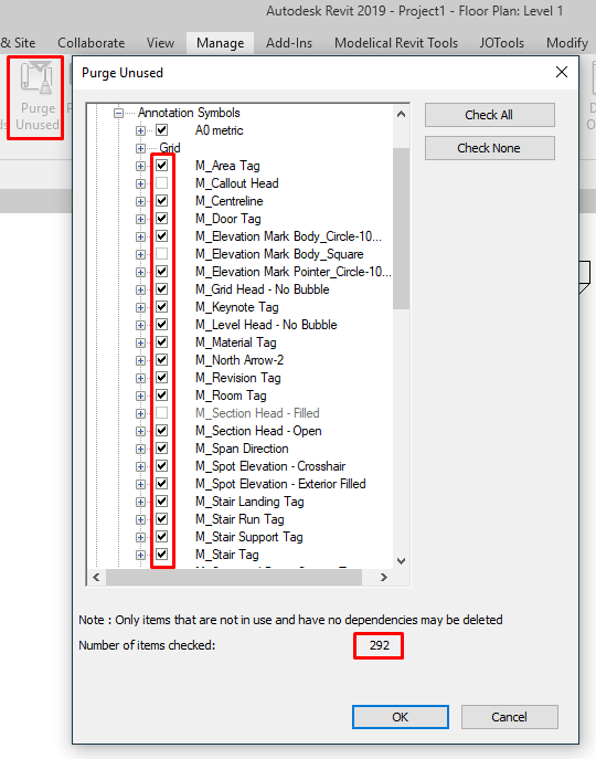
If we want to purge it all, it might be necessary to click Purgue Unused → Ok, several times, until the “Number of items checked” is 0.
Constraints
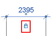
Minimal constraints will help prevent: “Can’t keep joined” errors to a minimum when moving objects:
Hosted elements
The use of elements of linked files as host of the project items is not suitable. If they were modified in the original file, when recharge the link, these elements would be orphaned, negatively affecting the performance of our model.
Audit
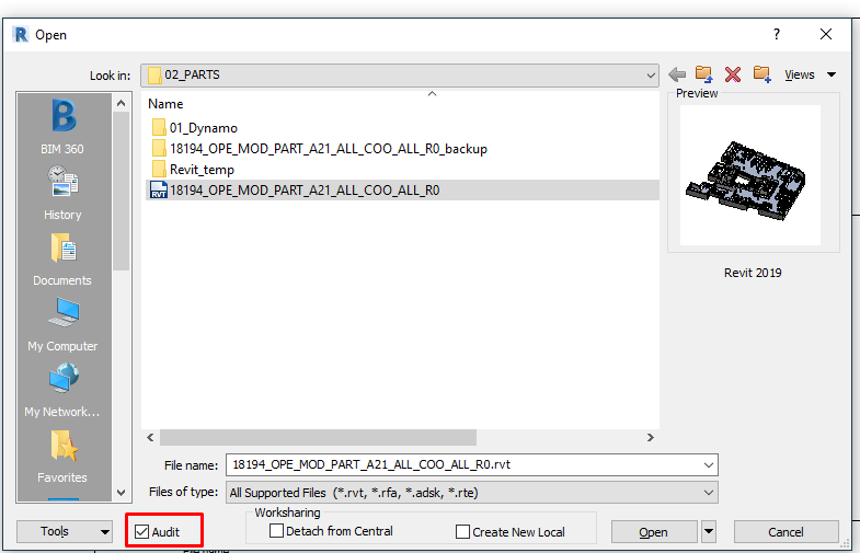
When we are recentralizing a model, or upgrading it to the next Revit version, it’s encouraged to Audit it. If corrupted elements are encountered during the audit, they are deleted if possible and the user is notified.
CAD files insertion
DWGs are one of the primary causes of increased file sizes and reduced model performance. When possible, minimize DWG links and imports. In an ideal scenario, DWGs should only be used for reference and then removed once native Revit elements have been generated.
Only link essential DWG files into necessary views (current view only).
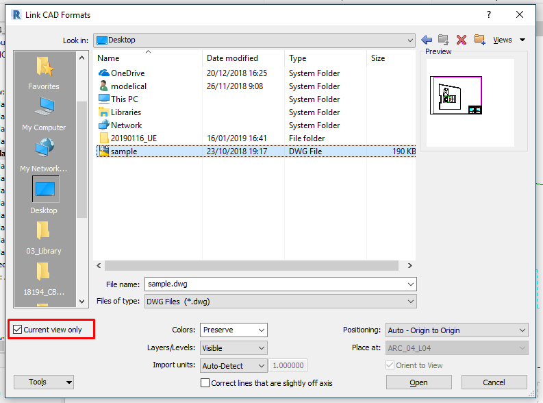
The difference between Link CAD and Import CAD is that a linked CAD gets updated, while an imported CAD doesn’t.
In Revit, never explode an AutoCAD file with attached XREFs. Each XREF will be treated as an imported symbol, and even if the XREF is deleted, it will add extra data to the file that cannot be removed, unless someone runs “purge unused.” This extra data can reduce performance and be extremely difficult to detect. The solution could be to Import the AutoCAD file into a separate Revit file, and link this “Dwgs.rvt” to our revit file.
Avoid importing unnecessary data like hatching. Delete unnecessary parts and layers of the DWG file within AutoCAD and import only the cleaned, purged smaller DWG.
Place the drawing close to the 0,0,0, referred to a known point.
If you are going to link dwgs as sheets, it is a good practice to prepare a dwg file with 4-5 layers depending on the graphics, and use them for its lines. In this case, when you import it, you can control better the mapping of each layer.
If you are going to use this dwg drawing as 2D detail in a family, the best option is to explode it and convert the lines to revit detail lines assigning the proper subcategory, and purge the ones that came from the dwg layers.
To finish, it’s important to purge the linestiles that might have come from CAD (we can achieve so by executing a free plugin called “Purge Line Types”, or we can go to Manage Tab / Additional Settings/ LineStyles), and to purge also the CAD patterns (we can achieve so by executing a free plugin called “Hatch Kit”).
Project configuration
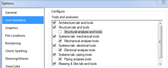
Disable the automatic Analytical Support Check feature if you are not going to use it, it may significantly improve the performance of the model. To disable the feature, go to “R” -> Options -> User Interface, and uncheck “Structural analysis and tool”. Please make sure to modify the User Interface setting in ALL user local computers that are working on this project.
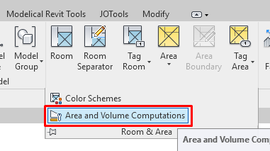
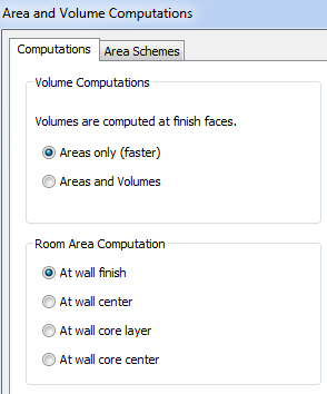
Turning off volume computation can improve performance but will disable much of the volume analytical functionality in Revit MEP. When volume computation is off, Revit will represent rooms as simple extrusions, without considering ceilings, roofs, floors, or other upper or lower boundaries. Because volume computations may affect the performance of your Revit project, they are disabled by default. Turn on volume computations when you need to:
- Show more accurate room color fills in section views.
- Have Revit compute the volume numbers for each room prior to printing scheduled room volumes. o Export a gbXML file.
- Perform building performance analysis.
- Account for the location of elements in volumes based upon the bounded volume geometry.
If you need to enable the volume computation go to Architecture/Rooms&Areas/:
Project First Steps
Splash Screen/project information
The splash screen is a sheet (Title block family) that contains the main information of the project and the file you are opening.
To make it the view that comes up when opening the file (starting view): Manage>Starting View
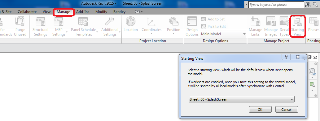
Using this view while synchronizing will reduce the time in the process, because it doesn’t need to regenerate any element. It's important to close hidden windows.
Copy or monitor levels
Levels are of great importance in the project, and its modification causes a significant amount of changes in the model, which increases as the project progresses. In fact, when there is a change, it is recommended that a single user do so without having any other person working on the project, since it will cause changes in a large number of elements.
The levels are especially sensitive when deciding how to work with linked files. There is no method that is right for all types of projects, we would rather have to examine each case to see the suitability of the method for working with them, since you can opt for different variants.
Do not copy levels without need
Sometimes it happens that the linked files just serve as a reference and we don't need to take elements of them to control our model. In that case despite having different levels (for example with files structure that have the levels slightly below the architecture) we will not need to reference any element to the levels of the linked file, so the best option is not to overload the model with unnecessary levels that will decrease its performance.
Collaborate → Copy/Monitor
In order to keep control of the levels in a link, an option is to “Copy monitor” them. By executing this, we are creating new elements in the current file, which will always reflect the position of the linked object. The advantage offered by this system is that we can work with the levels by linking elements to them because they will be in the model, and also if you change them in the linked model we will get a warning that it has been modified. When that happens we will see what has been modified in the coordination review menu, and we will decide if we accept the modification or not.
Coordination model
When it comes to very large projects with a high number of shared models, a good method can be the creation of a model where the elements of reference are located: levels and grids. They will be copied/monitored in the other models.
Thus the elements of reference will be fixed in a model, and all the other models will depend on that, making coordination much easier and avoiding unwanted movement of the reference elements occur.
The most important thing is to clarify the general criteria for levels. It must be clearly defined whether to create levels at the level of finished floor level, if there will be levels of structure, in which models are created and copy, etc. The most important thing is to avoid any user to create their own levels regardless of the rest, and that the model ends up having a large number of unnecessary levels.
Project browser organisation
Sometimes it is necessary to sort the views in groups and subgroups depending on their users, or the uses for which such views are intended.
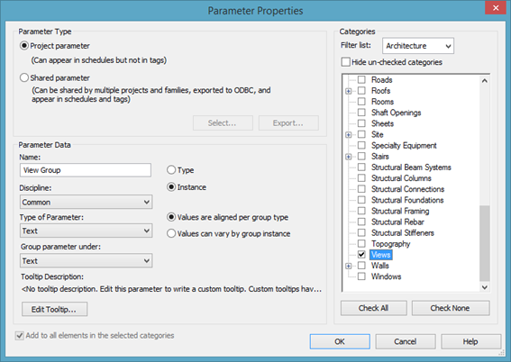
Views are organised into VIEWGROUP and VIEWSUBGROUP. They are two custom parameters* applied to views that organize the project browser. If a view group has been set up already, it will appear in the view group drop-down. Type new names are required.
- Choose the option Project Parameter, it is not necessary to be a Shared Parameter.
- Type a name, in this case 'View Group'.
- Choose the type of parameter, in this case "Text".
- You choose the heading under which you want the new parameter to appear in the Properties window, in this case "Text".
- The parameter applies to instances and not by type, since we want to apply to each view in particular.
- Finally it should be noted to what categories of objects we want to add this parameter, in this case "Views"
Once we have created these parameters, we can use them to manage the Project Browser. The Project Browser organization can be managed from: View/User Interface/Browser Organization:
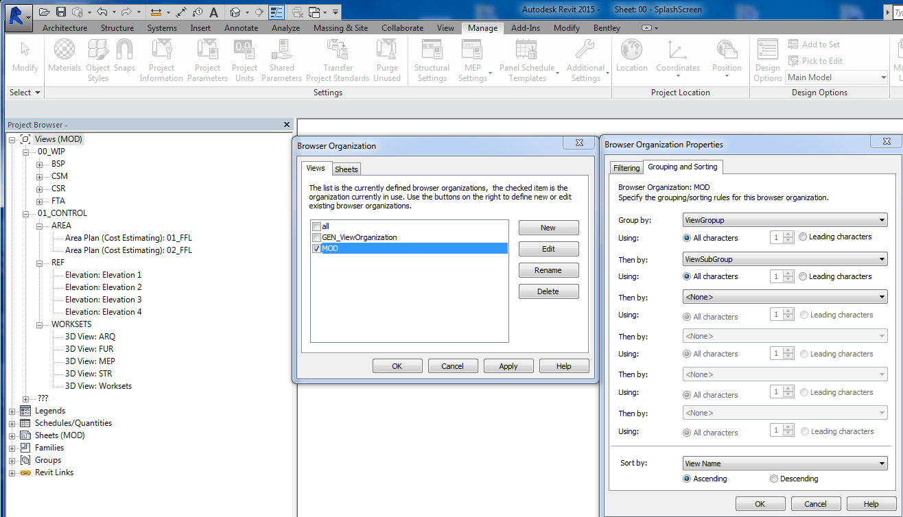
Every team member working on the project should have their own views to avoid any conflict.
If View is sitting in view group/sub group “???” then no category name is yet assigned. Every view kept at “???” can be removed anytime by your BIM manager/coordinator.
It is important also to create some views for workset control or any other views we need to keep the model classified.
We can also filter the view, for example, filter them so we only see the views which are not assigned to a sheet. In order to do so, we have to go to the Filtering section of the previous window, and Filter by “Sheet Name” or “Sheet number” → Equal to → None. This way, we will only see those views which are not assigned to a sheet.
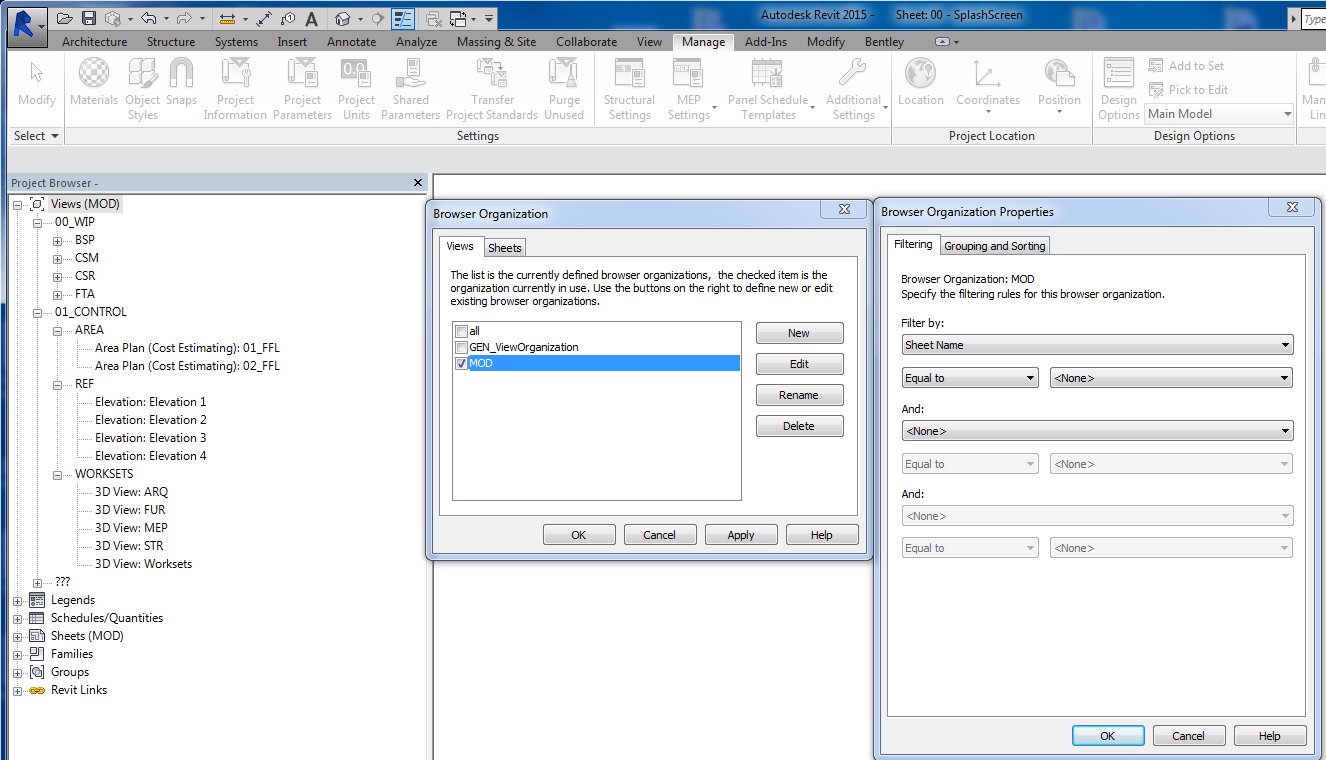
Suggested organization of Project Browser
01_WIP
Personal, work in progress views, codified per user
- XXX
- YYY
02_CONTROL
Views that should always exist and help control the project.
- Worsets
- Export
- Coordination
03_PRINT
Views to be placed on sheets, they should have view templates assigned.
- 0100-Situation
- 0200-Areas
- 0300-Sections
Sheets organisation
Sheets can be classified as views in the project browser. In this case we need the ViewGroup parameter assigned to sheets too. We can organize them by sets like:
- 0000 - LOCATION AND SITE,
- 0100 - AREAS
- 0200 - DIMENSIONS...
Modelling architecture
Modelling hierarchy
When our starting point begins with a CAD file we should take care of some aspects before drawing, and put some brain on it. We can not trust the CAD file because its accuracy could be very low. For all those aspects it's important to follow the recommendations indicated in the guide BST_STR_BestPractices, chapter Modelling hierarchy.
Walls
*See 30035_OPE_WallLayersAndLocationLine

If the target of the BIM model is to get the Bills of Quantities and/or to have a 4D planning, the way for modelling this wall has to be different, becoming three independent walls with their faces in contact.
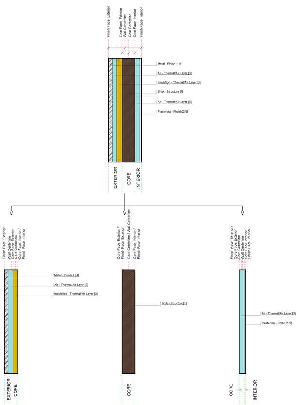
Revit offers the option Create Parts, which is not recommendable because if we use this tool to split an element, we will have to keep specific control of the visualization of each view, specifying if we want it to represent the elements by parts or by complete entities. This tool also presents problems when it comes to colouring a certain layer of the element, for example, if we want to produce a floor plan view in which the plaster of the walls are drown in red, and these plasters have been identified by Create Parts, we won’t be able to apply a filter solely for it. That is the reason why we encourage to model layers independently in order to have constructive, economic and graphic control of them.
This situation results in 4 types of wall by their use: supporting walls, facade claddings, wall linings and finishes.
- In the supporting walls, a determination has to be taken and you have to be consistent with it: which layers we put on the interior side and which layers on the exterior side. My choice is to put single or especial layers (WR/FF) on the interior of the wall and regular or double layers on the exterior. Location line will vary depending on its position: wall centerline, finish face exterior or finish face interior.
- In facade cladding we will put the layers on the exterior side and we will use the location line “finish face interior”.
- In lining walls we will put the layers on the interior side and we will use the location line “finish face exterior”.
- In finishes, as in cladding walls, layers should be located on the interior side of the Wall, remembering to use “Substrate [2]” function for the bonding material and “Finish 2 [5]” function for finishes layers. Location line must be “Finish face exterior”.
Doors
When you are creating a door frame with a sweep, and you need to use an specific profile, you are not able to nest instance parameters between the profile and the family parameters.
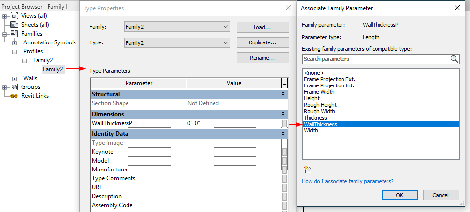
To get the frame adapted to the wall thickness, a solution is to create inside the profile family a Type parameter called “WallThicknessP”, and inside the door family a Instance Reporting parameter called “WallThickness”. Then, we load the profile in the door, and from the editor of the door, we modify the properties of the profile, setting the “WallThicknessP” parameter to the value of the “WallThickness”, like this:
Railings
Avoid the use of railings for extensive fences or separation systems and limit the visibility of such elements. There is no warning offered by Revit, but performance is impacted because of the number of lines required to generate each railing element. If a lengthy railing element is desired, consider modeling a simplified railing representation, relying on railing details to fully describe the design.
Rooms and levels
Room separation lines help divide rooms where no other bounding object is present. However, be careful. When these lines begin to overlap with other bounding objects, such as walls and columns, they will cause errors. The use of room separation lines should be minimized as much as possible by using room bounding elements whenever appropriate. Promptly resolve warnings about room boundaries overlapping.
Set room or space separation line color to red with a heavy line weight so they are easy to identify. And place them on one workset for better control.
Limit the use of rooms in design options, as additional time is spent detecting room option conflicts. If it is necessary, use external options like dynamo to save the room information in a excel sheet, and delete them from the model. In this case you will gain speed while modelling because Revit will not calculate the area and volume after any single wall drawn.
Avoid to place rooms inside groups. Many can end being unplaced/not properly enclosed rooms.
Rooms do not get along well with level offsets. They like to be placed directly on the correct level. This can be done by placing the rooms in a view that is associated with the right level.
Rooms don’t like floors protruding from the level they are placed on. Avoid having the base constraint of a room below the upper face of a floor.
Only select the Room Bounding option for linked files if they are absolutely needed to bound volumes (rooms and spaces). Revit will need to process these additional boundaries, which can affect model performance. This option is a type parameter of the linked file.
Reference planes
Name reference planes. If not, you are not able to use them as a work plane.
If you need those planes for different purposes (place beams, attach walls, cut structure elements…), name them properly. You will avoid misunderstandings between disciplines or people that use or move a specific plane.
Since Revit 2017, you can filter Reference planes in your project.
Model lines
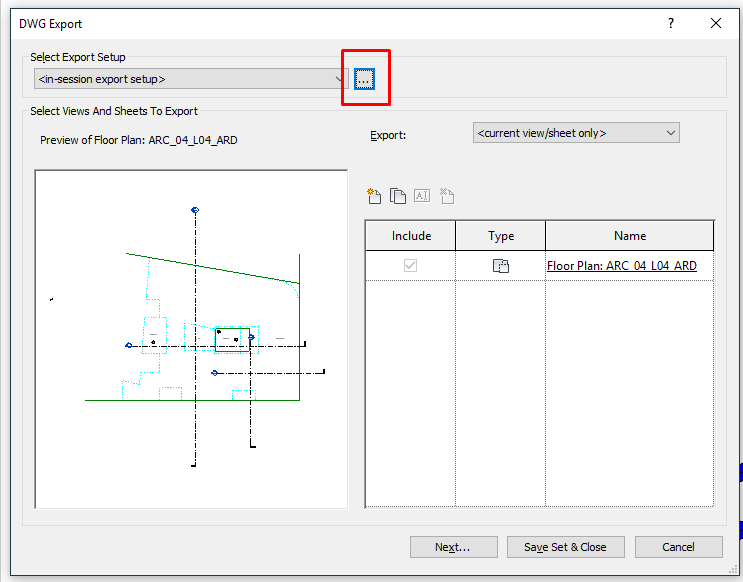
When exporting a Revit model to a CAD format, you can decide whether to maintain model lines that coincide with other lines in the same space. Use this feature if an exported file is missing some model lines. To ensure that these coincident lines are preserved in the export data, go to File/Export/CAD Formats/Export settings/General/Preserve coincident lines
:

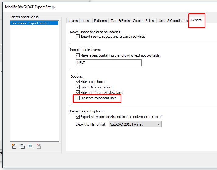
Model lines appear in every model view in the Revit project. They should be used sparingly since they are easily mistaken for a drawing error in other views. Where possible, replace model lines with detail lines.
Visibility
Adjust for better performance
Turn off shadows in most views. (Turn off shadows when printing views if not absolutely necessary).
Minimize view depth, if possible, in elevation, plan, and section views. In addition, use section boxes when working in 3D views.
Minimize view quantity to help reduce model size. To optimize static models to be linked into active models (for instance, in the case of an existing contextual building model adjoined to a model of new construction), delete as many views as possible from the static model to be linked.
Close hidden windows: Revit will update all currently open views affected by changes in the model. Selecting “Close Hidden Windows” will close the concealed views, allowing Revit to update only the current view with changes until other views are reopened.
Use shaded or wireframe display mode when possible for better performance.
To edit visibility/graphic settings in views in order to place them on sheets use the hidden line mode as starting point for changes, it is easier to add patterns that control the visibility of our objects.
Object styles
There is an important hierarchy among the visibility settings. Modify firstly the more general aspects, to finish with particular specific elements to avoid some repetitive modifications.
- Project Object Styles. (It affects to the whole project)
- Visibility / Graphic Overrides
- Visibility / Graphic Overrides > Override Host Layers > Cut Line Styles
- Phasing Graphic Overrides
- View Depth – “Beyond” line style (when an element is placed between bottom plan and view depth at the view range tool. Its lines will be represented as beyond lines)
- View Filters
- Override Graphics in View > By Element
- Line Work (Click a line > Type LW > select line type)
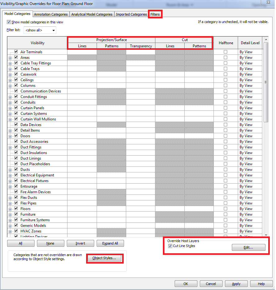
There are also subcategory graphics. It is important to have them in mind when creating new families, and assign the proper subcategory to the elements.
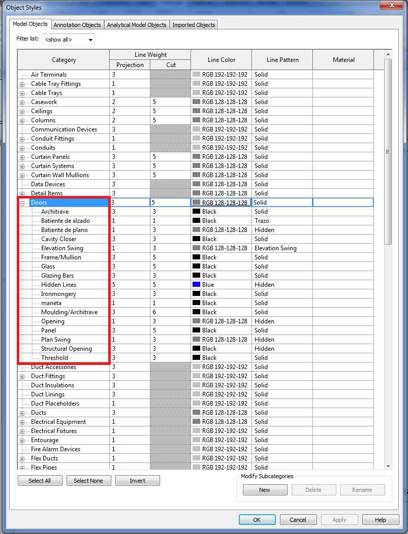
In the project, objects in family subcategories will be represented as the subcategories are defined in the project file (rvt) and not with the graphics that subcategories have assigned in the family (rfa) file.
View templates
Only include in the view template the elements which are common between views, it might be interesting to leave out worksets or links configuration:
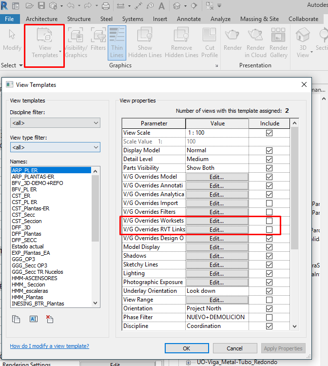
It is also a good practice to name them properly, as they are assigned to sets of sheets or WIP. Make the name reflect what the view template was created for.
Families
Detail level
Do not overmodel. The 2D version of a family is 20% smaller than the 3D version. Multiplied over an entire project, a larger family can add significant weight to a model.
Set the detail levels for plan and elevation representations (coarse, medium, or fine) and view-specific display options in the Visibility settings. Use symbolic lines and masking regions instead of geometry in plans. Stay minimal when modeling geometry by taking advantage of visibility settings.
Limit the use of detailed, nested, and parameterized families. Parametric families place a greater computational burden on the model than static families. Consider carefully whether a family needs parametric flexibility and confine that flexibility to necessary adjustments.
Avoid overusing voids in family geometry.
In place families
Create family components instead of in-place families if the components will be used repeatedly. When an in-place family is copied (which may cause additional problems), an entirely new entity is created each time, instead of just a reference to the type information from the first instance. For example, an in-place truss that is 200KB in size may be 3KB for next placement as a family, but as an in-place family it would require another 200KB of memory.
In addition, when you copy a “in place family”, a new element is generated, so you will have a long list of the same element in the project browser.
Family editing
When editing family parameters remember to duplicate the type first, to avoid editing original types and affecting project instances.
When creating or editing any of your project families, backup files obviously appear in your family folders. This can as much as quadruple your data usage at the family folder size. It is vital that you periodically remove all of the backup ‘.rfa’ files within your family folders. This will also avoid mistakes by staff attaching backup ‘.rfa’ files rather than the main file.
Legends and phases
The tool that Revit provides for creating Legends is not the best tool to create them, because you cannot tag the elements. To do it there is a option using phases:
- Create a new phase named Legend.
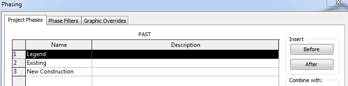
- Draw your legend elements somewhere far from the building. Apply to these elements the phase we have already created.
- Create a phase filter named Legend
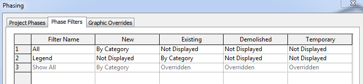
- In Phasing settings, configure the phase filter “All” to visualize just the new elements, and not to see the legend elements.
- Create some views cropping the elements you need in each legend.
- Check in all schedules that the phase of them is not the Legend phase, and that the Phase filter of the view does not show it. If this phase is visible in any schedule, Revit will count the elements used for legends as if they were part of the model.
Tips&Tricks
- It’s key to keep the weight of the file to the minimum. To do so, it’s vital to avoid unnecessary backlog in views, families, design options and imports, among others.
- It’s key to keep our elements adaptable, thus, minimal restrictions should be imposed.
- The coordination between files should be achieved by a Coordination model for huge projects, or the tool Copy/Monitor for minor buildings.
- When modelling, the hierarchy between elements should be respected in order to keep the right connections between them.
Bottom-line
Revit offers interesting functionalities when it comes to representing, quantifying and planning buildings, but a good management of the model is key to keep our files light and organized. This document explains several aspects that help the modeller achieve such good management.
Muy buen contenido !!!.
Congratulaciones por el esfuerzo dedicado a la redacción y edición. Publicar estos temas ayuda a muchos interesados y a los que estamos inmiscuidos en el uso y difusión del REVIT con todas las ventajas que tiene el programa.
Gracias sinceras y muchos saludos !!!!
Hello Roberto Molinos.
i read your post , it was really very important to me , much issues was benefit .
i thank your very much for your effort
Thanks..
Como resuelves el problema que presentan las puertas/ventanas cuando se modela los muros separados? 1.) El perfil de la puerta solo se ajusta al grosor del muro donde fue insertado y 2.) Si quiero que el recubrimiento cubra el hueco, tampoco puedo, porque las capas no están en el muro anfitrión, sino modelados aparte
En ese caso debes crear tu familia de puerta con un parámetro que te permita fijar la profundidad del marco de forma independiente.
También puedes darle “Join” a los muros separados, es decir, al muro base con el muro acabado y en automático te respeta el hueco de puertas y ventanas. Slds!
Excelente contenido!! muy util todo! gracias!!
Very informative
Very informative. I will definitely want to receive future posts notifications
Y ademas podes hacer un join o union entre esa capas asi se cortan todas con la insercion de la puerta (+ la respuesta anterior)