
2D details
Strategies for including them in the Revit model
Strategies for including 2D details in the Revit model
Objectives
To know the different possible ways to include 2D details in a Revit project.
Prerequisites
Being a Revit user and needing to generate the construction details of a project and include them in the model.
Introduction
First of all, we think it is necessary to list the details that a project includes.
We like to organize them in 3 types of details:
1- The "type details", of the typologies of constructive elements, or also called reports or tables.
E.g.: carpentry report, walls report, pillars table... It is the definition in plan and/or section of the constructive elements of the project. (They are usually reusable)
2- The "encounters details", of the type encounters. For example: encounter of slab with concrete block wall, or corner encounter of a ½ foot sheet of brick masonry. (They are usually reusable)
3- The "singular details", of own constructive solutions that are solved exclusively in that project. Example: Construction section. (They are not reusable but specific to the project).
We would say that the Revit tool par excellence to draw details in 2D, is the Drafting View, with the possibility of being shown in plan and also in section. However, in the projects we find all kinds of ingenuities to get the 2D details in the models in the most efficient way.
Depending on the type of detail we have to show, we may want to use different tools to explain the project better and with as little work as possible.
Hereinafter we will see the most frequent strategies for inserting 2D details in a Revit model, as well as their possibilities, advantages and disadvantages.
Procedure
To begin with, we will show a comparative list of the most common procedures and their characteristics and then detail them individually.
CAD | Detail items | Drafting views | Detail views | Legends | Phase for legend | Design option | |
Can be drawn with annotation elements | No | Yes | Yes | Yes | Yes | Yes | Yes |
Can be Dimensioned | Yes | Yes | Yes | Yes | Yes | Yes | Yes |
Detail items can be inserted | No | Yes | Yes | Yes | Yes | Yes | Yes |
CADs can be inserted | No | Yes | Yes | Yes | Yes | Yes | Yes |
Legend component exists | No | No | No | No | Yes | No | No |
Can be modeled | No | No | No | Yes * | No | Yes | Yes |
Can be labeled | No | No * | No * | Yes | No * | Yes | Yes |
Can be referenced | No | No | Yes | Yes | No | Yes | Yes |
It is inserted in Views | Yes | Yes | No | No | No | No | No |
It is inserted in drawings | Yes | No | Yes | Yes | Yes | Yes | Yes |
The scale is controlled | No | Yes | Yes | Yes | Yes | Yes | Yes |
The order in which the different options are explained is related to the level of complexity required to use them.
1. CAD
Introducing a CAD detail directly in the model, would be the most basic and a priori less laborious way to get a 2D detail, since the use of CAD programs goes back a long time and there is a good history of 2D details. In addition, drawing details in a CAD program is quantitatively easier and has multiple options that Revit does not have, or that are more laborious to achieve.
What CAN be done
- The list of possibilities is not very extensive, but something positive is that they can be dimensioned, since their lines are recognized in Revit as references, so some customization is possible.
- A CAD file can be inserted in a view as well as in a sheet, so we can have the detail directly in the final sheet, or go through some intermediate solution to have the details organized.
What CANNOT be done
- As it is a static element inside Revit, you cannot interact with it except for dimensioning, so you cannot use annotation or detail items, nor model, nor label, nor introduce other CADs... However, as it is necessary to position it on a sheet or view, you can use annotation elements inside that sheet or view.
- You cannot control the scale of the drawing with the Revit scale tool, but to change the scale of the detail, you would have to scale the inserted object, which is very dangerous because it can lead to errors.
Possible strategies
If we do it this way, at least let's take into account some tricks to make it easier to manage:
1- Introduce the CADS with the option to link, not to import. In this way, any modification of the detail from your native program can be updated in Revit by reloading the file.
2- Be consistent when naming the CAD files. It will be the only way to organize and manage the details, according to their name, so be careful.
3- Explode the hatches previously in CAD, since Revit does not recognize them as fill patterns, but as solids.
4- Always use the same layers, so that in Revit it is easier to manage their visualization. Moreover, if in CAD the colors and thicknesses of the lines are already established, in Revit it would not be necessary to make any extra modification.
When inserting or linking a CAD in Revit, it establishes a thickness and a color to the layers that come from autocad according to what is configured in the CAD layer itself, therefore, if in CAD this is worked and defined, in Revit it would not be necessary to do anything.
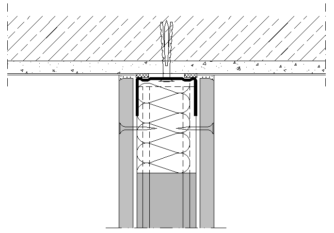
Example of detail without working thicknesses and colors in CAD:
Example of detail with layers worked in CAD:
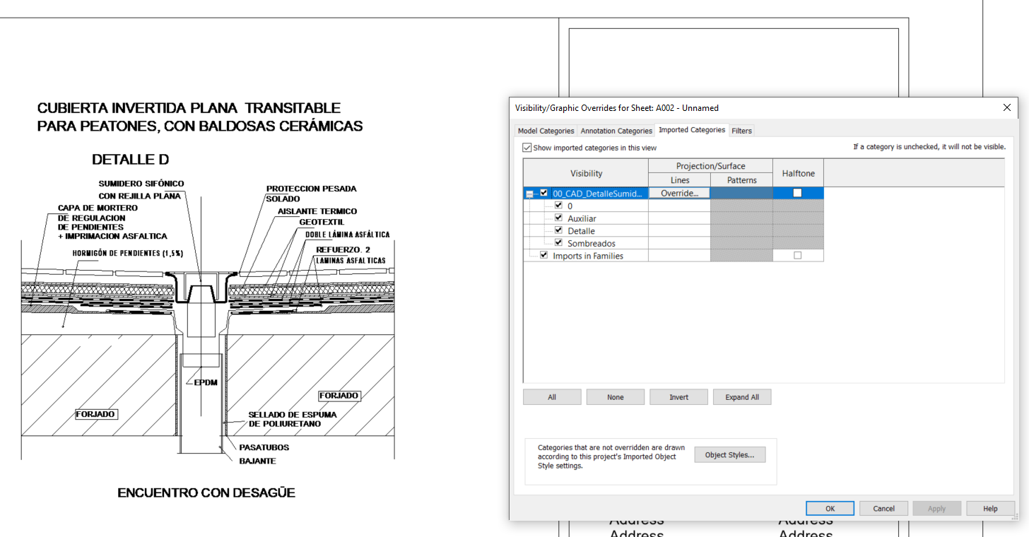
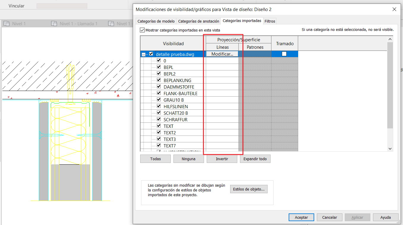
The display of the layers coming from a CAD file can be modified from the graphics visibility of each view, but also globally for the whole file from the Manage tab - Object styles - Imported categories. In this way, they apply to all the views where that .dwg is linked, and it is not necesary to change it view by view.
We discourage any other practice that consists of decomposing CAD drawings in the model, since each CAD layer generates a line type in Revit, and this entails a high amount of subsequent work in definition and/or classification of those line types, which is an equal or greater effort than directly creating a detail item family (Detail Item) that is native to Revit, cleaner in terms of line types, manageable and reusable in other projects.
In case you want to do this, it would be key to insert the CAD detail with a layer nomenclature the same as the name of the line style you want it to go to, since it is mapped automatically with the line styles existing in the model, instead of creating a new line style.
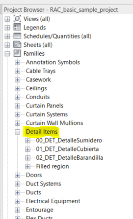
2. Detail Items
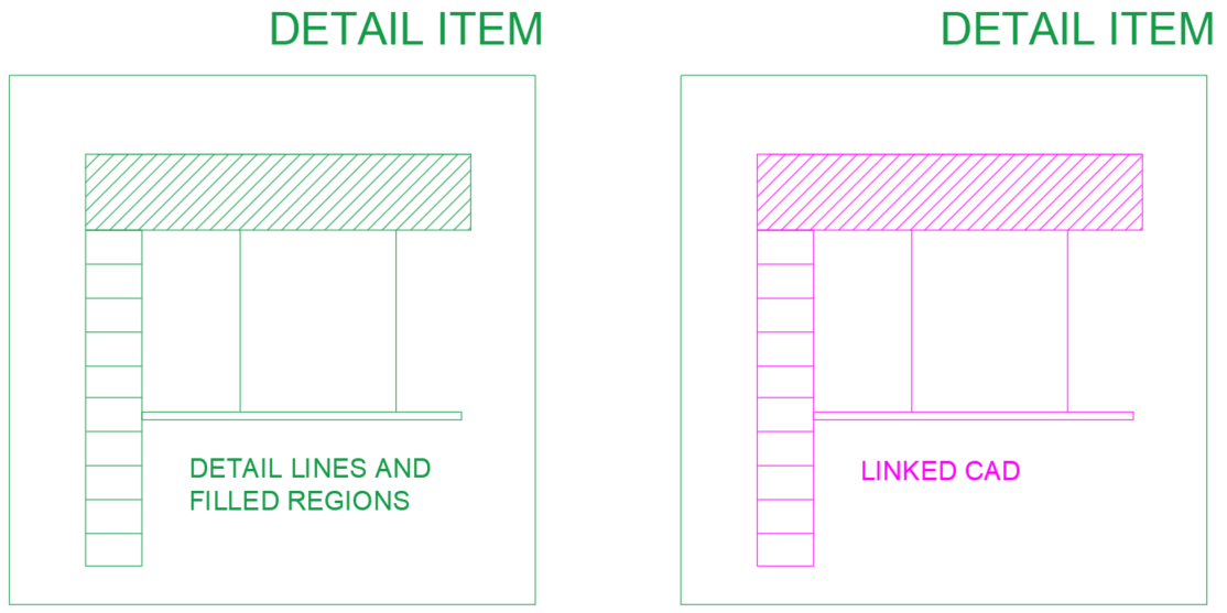
This is a Revit family with its own category, in which a 2D element is drawn. Here you can draw construction details, as well as symbology (for example the North symbol), or any 2D drawing that is likely to be used many times in different projects.
In order to achieve a correct visualization, as many line styles as necessary, as well as fill patterns for shading, will have to be created.
What CAN be done
- Within a Detail Item family, we can dimension, as well as create in the family itself, the desired generic texts or annotations that identify each of the elements. In this way, when inserting the detail in the model, it already appears with all the necessary annotations. It can also be saved without annotations, or include them in some visibility parameter, which makes it possible to activate and deactivate them. It would also be possible to create different types of details in the same family by assigning visibility parameters to the lines defining the details.
- Like any family, it is also possible to nest other families that are of the same category, and even CAD files.
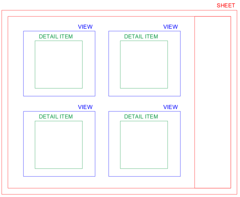
- They can be inserted in views, but they cannot be inserted directly in drawings, so in order to use the detail items to create a drawing, it will be necessary to go through an intermediate view, either legend, drafting view, detail view... or any of the cases explained below.
What CANNOT be done
- Detail item families do not have the property of modeling 3D elements, so they will only be visible in the view in which they are placed.
- They cannot be placed directly on sheets, but must be placed on views.
- As they depend on a view where they are placed to be displayed in a sheet, detail items cannot be referenced directly from that sheet, but the view in which they are inserted must be used as a reference for that detail.
Possible strategy
As previously mentioned, the detail items have to be placed in a view, so the way to work with them would be to use them as a bridge.
It could also be combined with the use of CAD details, since they support the insertion of this type of files, being a way to be reused and have them saved and organized within the project browser.
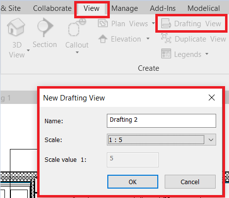
3. Drafting Views
Drafting views are created from the view creation menu, by clicking on the Drafting Views icon; then a menu appears where you can name it and choose its scale.
Once created, it will be classified within the project navigator, as if it were any other view.
What CAN be done
- In the drafting views, we can insert detail items as well as CADs, so we can combine these options.
- In addition, you can dimension and use all kinds of annotation elements.
- The possibilities to create 2D details within the drafting views are multiple, and the most interesting thing is that they can be referenced both in plan and in section, in order to indicate in the sheet the detail number and in which sheet it is located within the project using Revit calls.
What CANNOT be done
- The drafting views do not allow modeling 3D elements, only annotation elements, therefore, the possible labels will be those of the annotation elements, which normally do not have much content.
- As they are, to all intents and purposes, just another view, they cannot be placed in another view as if they were a detail item.
Possible strategy
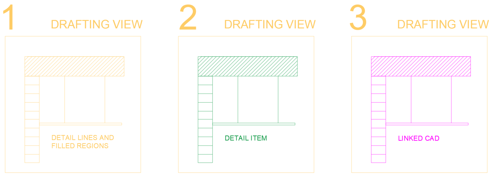
There would be several possibilities to use this type of view, we will explain the 3 most common ones.
1-Draw directly the details, some outline, etc within the drafting view. We do not recommend it, because as always, it would be necessary to do a good exercise of line styles and shading patterns, so it is not the most efficient option and since we are going to do that work, it is worth to draw the detail in a detail item family and save it in the family repository for later use on multiple times.
2-Insert detail item families within the drafting view that correspond to the area marked in plan or section, and then enter the referenced view in the drawing.
This option requires an initial work of creating Detail item families, but it is the cleanest, and although it has a previous effort, it will be the most efficient and reusable, therefore the one we recommend the most.
3-Link drawings created in CAD in the drafting view, with the precautions mentioned above in the use of CAD drawings, so that we have the details well classified and referenced within the project. This option is very interesting to work simultaneously in CAD and Revit, being always coordinated.
Although it is a comfortable and fast option, we must not forget that we will have to do a good CAD layer management, and that Revit will not always give us the expected visualization, since a CAD is not a Revit native element.
To reference the drafting views, you can use the option to reference to view:

And also, much more conveniently, from the callout tool itself.
When clicking on the call icon, and before selecting the call region, you should click on the >refer to another view< box and then select the relevant drafting view.
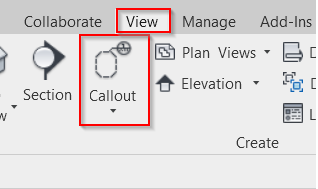
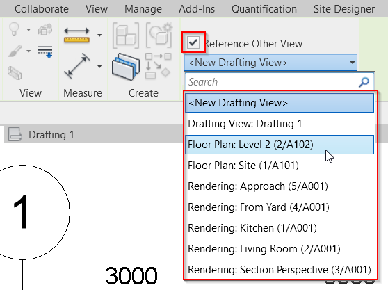
Subsequently the view it refers to can be modified, but this step must be done prior to drawing the view region.
4. Detail Views
They consist of a view that replicates a portion of the plan or section, according to the selected region, having the option to set another scale to show more detail or to add annotation elements, such as dimensions, lines, hatches, etc. to give more detail to the selected part.
They are automatically created when a callout is placed on a region of a floor plan and are classified in the project browser.
What CAN be done
- As mentioned above, you can draw with annotation elements, dimensioning, inserting detail items, CADs... but also, when working directly on the modeled elements of the project, you can use model labels.
- These views, in addition, can be referenced just like the drafting views, so it will be a very good option to mark in the drawings the detail number and position.
- These views work like any other view and are inserted in the sheets in a unique way.
What CANNOT be done
- There are practically no limitations with these views, however, they are only inserted in sheets, they cannot be inserted in views, unlike detail items, nor can they be combined with drafting views or any similar strategy.
- They cannot be reused, since they work directly on the model, on a specific detail and casuistry of the project.
Possible strategy
The weakness and strength of working with these views is that they are drawn directly on the model.
Weakness: If something changes in the model, we will have to check that the detail views still make sense, and that there are no displaced annotation elements or elements with wrong dimensions.
Strength: They will be very practical and comfortable for singular encounters of the project, since all the references are correct, the solution is made on the real model and the properties of the family can be consulted directly on it, since it is modeled.
What kind of cases can we have?
1- Normally we will want to add more detail than is seen by default in Revit, for example, in a plasterboard partition wall, we will draw the profiles that hold the plates or the insulation inside with annotation elements.
2- At other times we will not be interested in seeing certain elements that are modeled, for example if a sink appears in the selected portion, and we will have to hide it from view. You can hide lines using the <invisible line> style.
3- It is possible that we want to have the 2D detail without any reference to model elements, and act with the detail views as if they were drafting views, that is, views empty of content. For this we would have to hide all the modeled elements of the view and insert directly the CAD or the Detail item family. The latter makes sense if we want to take advantage of the "callout" in plans or sections. If it is not of interest to reference the detail with a callout, doing this would not be necessary, but another strategy could be used, such as placing a detail item, drawing directly on a sheet, etc.
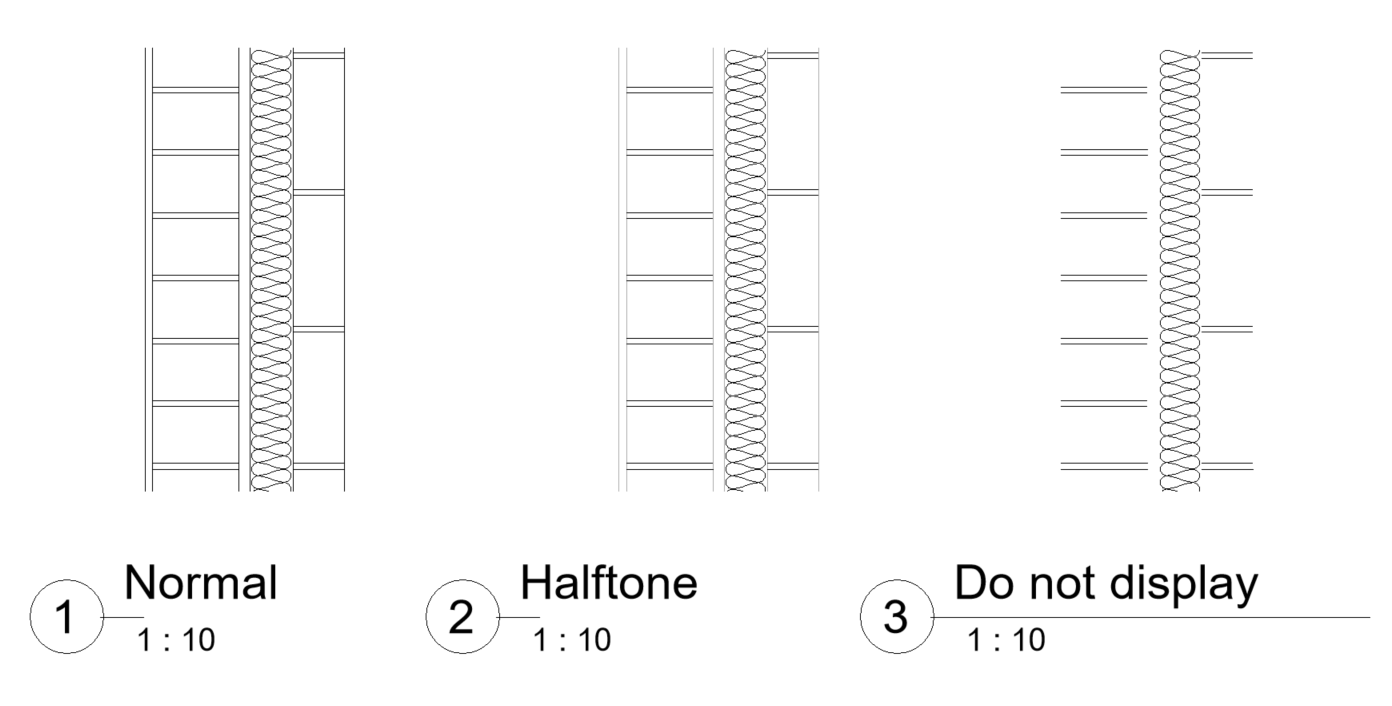
The detail views have the possibility to visualize the model in 3 different modes. Normal, halftone, where the modeled elements are lighter, and not displayed, where, as the name suggests, the modeled elements are not displayed.
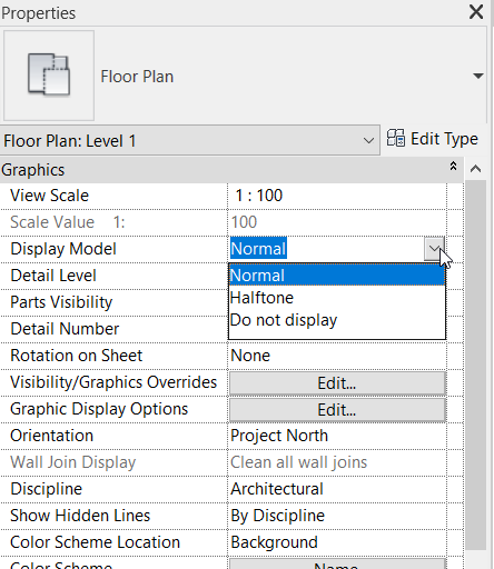
The combination of the three cases will be the norm depending on the encounter to be shown.
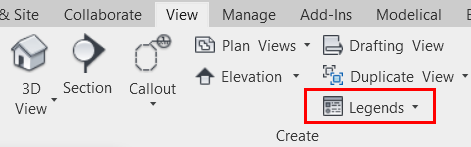
5. Legends
A legend is insertedfrom the view creation menu, by clicking on its icon, or from the project browser itself by right-clicking on the Legend title.
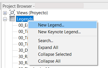
Legends are classified in the project browser, but, unlike views, sheets and tables, they cannot be subclassified, so using a good nomenclature will be key to keep them organized.
What CAN be done
- In a legend you can draw and insert all kinds of annotation elements: CADs, dimensions, lines, texts, fills, detail families...
- The most interesting thing is that there is a so-called legend component, which is unique to this type of view, and consists of a representation in plan or section of any family that is loaded in the project. This is very useful for example to make a carpentries sheet, or to make a legend of the symbology of installations. These legend components, although they represent families, are not families, that is to say, they do not appear in quantification schedules, they do not have customizable parameters, so they cannot be filtered or labeled. To all intents and purposes they work as a detail item family, only that they already exist in the project by the fact of loading the family, without having to do any previous work.
- The legends are inserted directly into the drawings, and can also be inserted multiple times, as opposed to ordinary views, which can be useful for using the same detail in several drawings.
What CANNOT be done
- The feature that makes it less attractive to use the legend to create 2D details is that it cannot be referenced from another view using a Revit callout. Revit callouts are very handy because they automatically indicate the number of the detail and the sheet in which it is contained.
- Legends cannot be inserted inside the views, but, as explained above, they are inserted directly into the drawings.
- Legends cannot be modeled although there is the possibility to use legend components.
- As for labeling, since it is not possible to model, not much can be labeled, limiting the labeling to annotation elements, which a priori is not of great interest.
Possible strategy
The main interest of the legends, as already mentioned, are the legend components, which allow you to have a section or plan of all the families of the project. These can also be drawn in more detail using the necessary annotation elements.
The most common application of the legends is to use them as legends themselves, or also to complete the detail drawings that we called type 1 at the beginning. Memories or construction element reports.
Their use to insert all types of details can be motivated by the organization of the details in the project browser and the simplification of a single solution for all details. In this case, we would have two scenarios:
1- Details are not going to be referenced, which is not a problem for "type details" (type 1) and "encounter details" (type 2), however, "singular details" (type 3) do have to be referenced, so for these we would have to look for another strategy.
2- Details must be referenced. For this, other solutions would have to be used, such as creating annotation families in which to indicate the information that by default appears in a callout, or directly writing it by hand with simple text (not a very BIM option).
6. Phase for legend
Another widespread option is to resort to a phase of the project where nothing is modeled, usually before all the others, where the elements needed to make the details are modeled.
This is usually done to solve the "type details", instead of solving it with the legend components.
In addition, it is used to have a kind of library of modeled solutions as a catalog where the designer can choose according to the needs.
What CAN be done
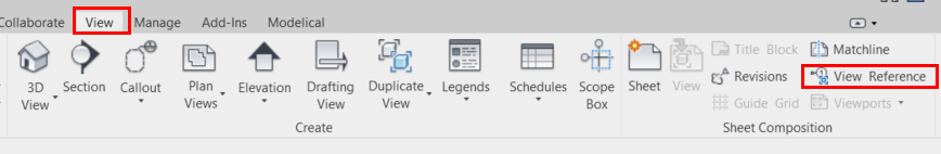
- You can do almost anything, since it is a viewport. Model, label, include annotation elements, CADs, and it can also be referenced in a drawing using the view reference tool:
What CANNOT be done
- What you cannot do is to use this view multiple times, like any other view, but you could duplicate dependent views so as not to lose the modifications you make and use different crop view regions to show what you want.
Possible strategy
If this option is used, it is mainly because of the ease of labeling. Legend components cannot be labeled, so all the additional information that is usually indicated in a carpentry drawing, for example, would have to be written by hand, while having the actual modeled element, the label can take care of any of its parameters, making the drawing much less time consuming and with more certainty as to the consistency of the information indicated.
It is a very useful strategy for "type details", however, for "encounter details" and "singular details" it does not make sense, and is normally used combined with other options.
As a drawback, note that when working with linked models, it is a good practice that they all have the same number of phases, to map them correctly. If the phases are not mapped, our collaborators from other disciplines could be seeing our catalog of elements in phases that they do not touch and this would be very confusing.
Always the phase of the catalog of elements should be prior to the existing phase and demolished in it, or even created and demolished in the same phase of the catalog and only see the elements by configuring a correct phase filter, so that there is no possible confusion when linking the model and above all, the modeled elements are not accounted for in the quantification schedules, because the measurements would be completely altered.
7. Design option
Using design options is a similar alternative to using another phase of the project, in which the elements needed to make the details are also modeled.
Similarly, it is often done to solve the "type details", instead of solving it with the legend components.
What CAN be done
- You can do almost anything, since it is a viewport. Model, label, include annotation elements, CADs, and it can also be referenced in a drawing using the view reference tool:

What CANNOT be done
- What you cannot do is to use this view multiple times, like any other view, but you could duplicate dependent views so as not to lose the modifications you make and use different cutting regions to show what you want.
Possible strategy
If this option is used, it is for the same reason as using another phase of the project.
It is a very useful strategy for "type details", however, for "encounter details" and "singular details" it does not make sense, and is usually used in combination with other options.
The correct thing to do would be to create a design option that is not the primary option, and then model what is needed. In this case, the primary option would be empty, since the design options function itself is not of interest.
The advantage over using other phases is that by default you will never see these elements, nor will there be any problems with the mapping of phases or with their appearance and posting in quantification schedules.
Summary
In summary, both drafting views, detail views and legends can be used with a similar strategy, always combined with the insertion of CADs or Detail item families, not drawing directly on the view. Any of the detail types of the project can be solved, each with their differences and their "tricks" to make them as practical as possible.
Using phases and design options would be a very practical option only for the "type details".
Below is a ranking of the best solution according to the type of detail that needs to be done.
Remember that each project may need a different strategy, or that sometimes, to simplify the model, it would also be a good option to use a less good strategy but that solves all types of details.
Detailing elements or CADs alone are not included in the ranking, as it is always advised that they serve as a support to another strategy, but not to be used as a strategy in itself.
RANKING ACCORDING TO TYPE OF DETAIL | Drafting Views | Detail views | Legends | Phase for legend | Design option |
| 3 | 1 | 4 | 2 | 5 |
| 5 | 4 | 3 | 1 | 2 |
| 4 | 5 | 3 | 1 | 2 |
Tips & Tricks
- When inserting or linking a CAD, keep in mind that Revit does not recognize hatches as such, but all layers act as lines, so CAD hatches cannot be assigned Revit patterns. This will be important when modifying for example the color of a hatch, since Revit will not respect the pattern and will change it to plain hatch.
- If CAD layers are named the same as Revit line styles, when exploding a CAD within a revit family, the layers will automatically become those revit lines.
- The phases of a project can be mapped, but always following the same chronology of the phases of the target project. That is, you cannot map the phase new construction to existing and existing to new construction. Phase mapping is intended to be able to give different names to the phases and still be recognized, but not to alter the chronology of the project.
- Remember to click on the >Reference another view< box before delimiting the region of a callout to associate any type of view to a callout, otherwise you will not be able to change the reference view later.
References
The following guidelines explain in detail all the options available within the strategies analyzed.
DWG Insertion Protocol