Topography with toposolids
Topography with toposolids
Objectives
To know the applications that toposolids give us when working with topography in Revit and the different processes for creating them.
Prerequisites
- Autodesk Revit 2024 or later versions
- Autodesk AutoCad
- Rhino.Inside.Revit
- Rhinoceros 7 or later versions
Introduction
Toposolids is a tool available starting in Revit 2024 that is used to work with topographic elements that are defined from elevation points or imported data.
The main new features/differences with the topography from previous Revit versions are:
- The creation of a topography from a closed contour.
- The tool to modify the sub-elements of the toposolid.
- The option to add subdivisions.
- The creation of voids.
The following will explain the different procedures for creating a toposolid, either directly in Revit, from an import of a CAD or a list of points in a CSV file, or from a Revit topography from a previous version.
The different processes for manipulating toposolids and their visualization will also be explained, such as subdivisions, voids (tunnels, excavations...), visualization of contour lines... Actions that were not possible with a topography from a previous version of Revit.
Procedure
1. Creation of toposolids
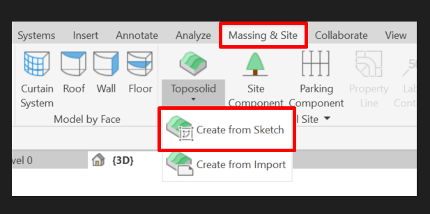
1.1 By sketch from Revit
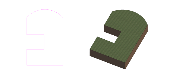
The most direct way to create a toposolid is to do it by sketch directly in Revit.
Unlike previous versions of Revit, where a topography was created from points without control of its perimeter, with toposolids we can control the perimeter and, from there, modify its sub-elements. A process very similar to the creation and manipulation of Revit floors. As we can see in the following image, we can generate perimeters with concave and curved parts.
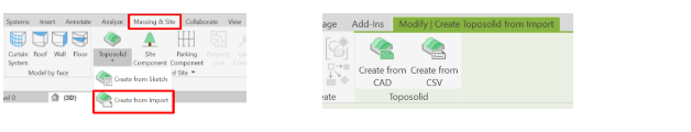
1.2 From an import
You can also create a toposolid from an import, from a CAD or from a CSV file.
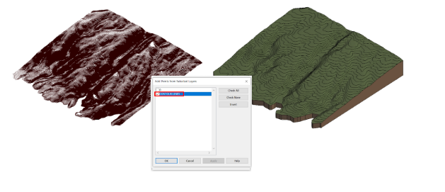
In the case of creating a toposolid from an imported CAD, it asks you which layer has the necessary elements to create it. In this case, the contour lines are in the CONTOUR LINES layer. In the case that the imported CAD has contour lines that represent a completely vertical face, the resulting toposolid won’t be able to be represented correctly.
To create a toposolid from a CSV file, you need a file with the coordinates of each point as we can see below. When you select the file, Revit asks you for its units and creates the toposolid with a sub-element for each point in the list.
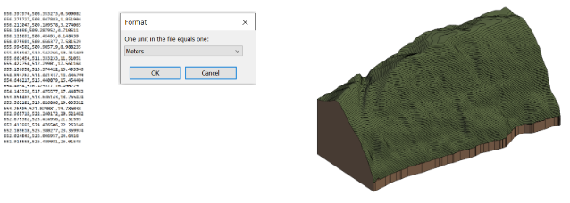
The resulting toposolids can be modified once created just like a toposolid created from a sketch. You can modify its sub-elements, its perimeter and change its type. We can also see that, unlike Revit topography, toposolids respect the perimeter of the imported elements even if they have some concave parts.
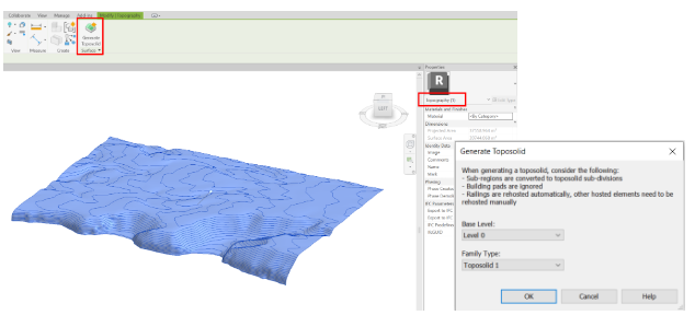
1.3 From a Revit topography from a previous version
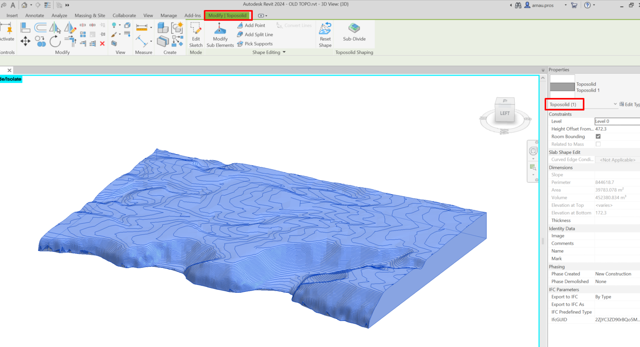
When we select a topography created in a file from a version prior to Revit 2024, the option to Generate Toposolid appears. To continue the transformation we need to reference the toposolid at a base level and give it a type. The original topography is not deleted and remains coplanar to the upper face of the generated toposolid. This new toposolid has the same characteristics and parameters as a toposolid created by sketch.
2. Modification of toposolids and their visualization
2.1 Sub-elements
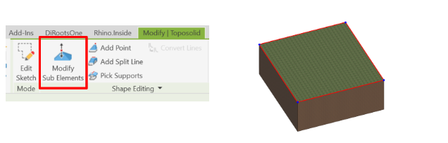
The sub-elements of a toposolid are very similar to those of a Revit floor. Modifying or adding sub-elements allows us to modify the relief of the toposolid. These modifications are made from points or split lines. The option to Modify Sub Elements allows us to modify the elevation of these points or lines. If no sub-elements have been added to the toposolid previously, only the vertices, in blue, and edges, in red, of the toposolid sketch can be modified.
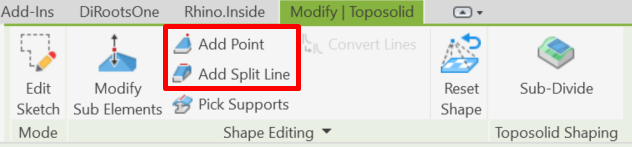
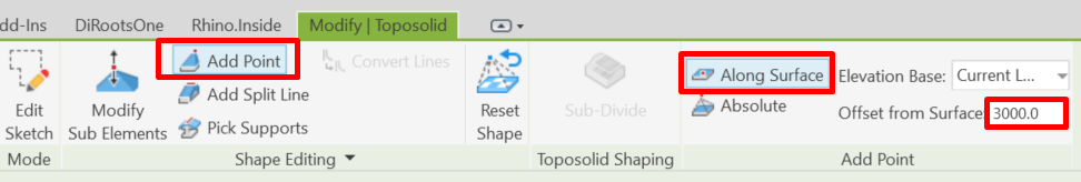
To add new sub-elements, we have the options of doing so from points or division lines with the options Add Point or Add Split Line.
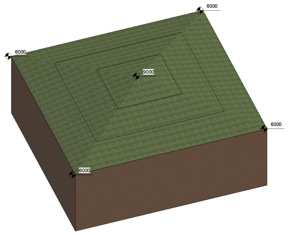
When we modify the toposolid from points, we are presented with the options of adding them along the surface or in absolute values. If we place the point along the surface, we can add a value that indicates the displacement of the point in relation to the level of the surface. If it is a positive value, this point will be above the current surface, if negative, it will be below (as long as the point is not below the base of the toposolid, in which case would not allow adding the sub-element). If the value is zero, the point would be added at the same level of the surface in that location and won’t modify its geometry. For example, if the surface of the toposolid is at an absolute elevation of 6000 and the point is located relative to the surface with an offset of 3000, the point would have an absolute elevation of 9000.
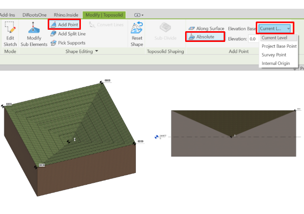
If a point is added with the Absolute option, the value will be with respect to the element that we choose within the drop-down menu (Current level, project base point, survey point or internal origin). For example, if the point is placed based on the current level (level 0) and with a value of zero, the point will be placed at the same height as the level, regardless of the current height of the toposolid at that point.
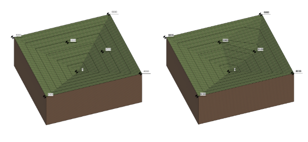
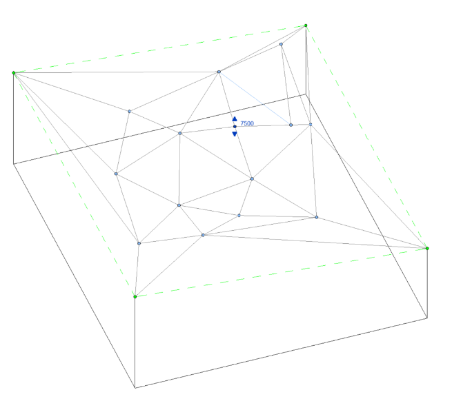
If we modify the toposolid with a split line, the elevation of the start and end point of the line will always be equal to the elevation of the surface of the toposolid at those points and when we select it we can vary its elevation, the one of the line and the one of the two points. For example, if we draw a split line between these two points on the toposolid with an elevation of 3500 and 3800, the ends of the line remain at those elevations.
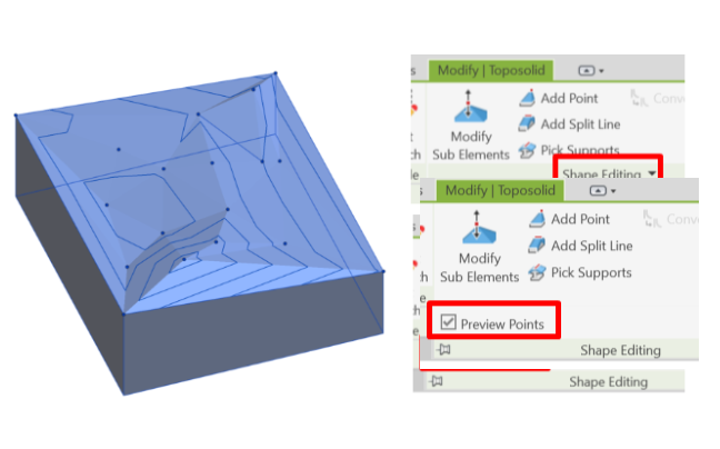
To be able to view the points and split lines without having to enter the sub-element editor, you must display the Shape Editor and activate the Preview Points box. They will become visible when the toposolid is selected or when the cursor hovers over it.
The elevation of points or split lines can be modified with the option to modify sub-elements and then selecting the point or line and moving manually the arrows that appear once you select it or by substituting the value that appears next to it representing its elevation. You can also modify its location in plan by selecting the center of the point and moving it along the surface. With the reset shape option you return to the original state of the toposolid and eliminate all modifications to the sub-elements. In the case of restoring the shape of a toposolid imported from a CAD or a CSV, it will maintain its perimeter but will become a flat toposolid.
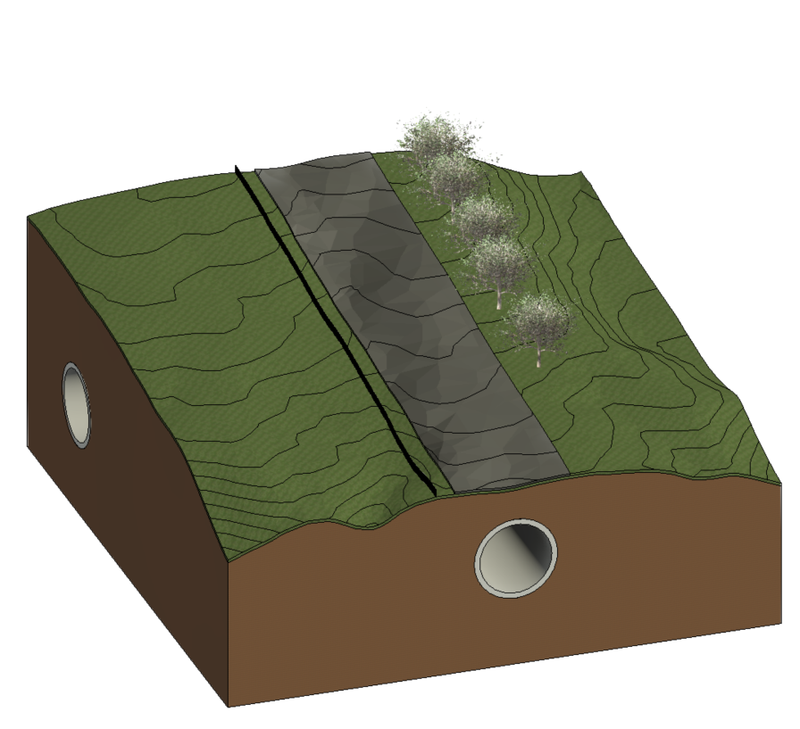
2.2 Subdivisions
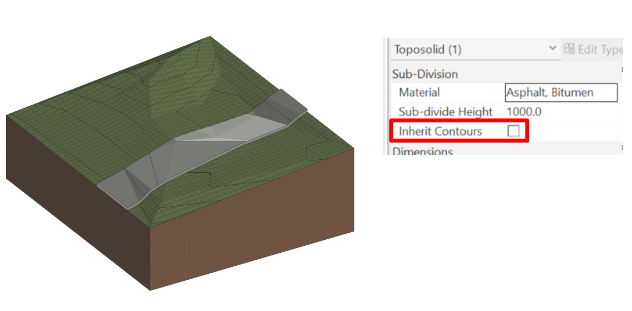
Subdivisions in toposolids allow one more layer to be added to its upper surface.
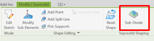
To create them, you must select the Sub-Divide option and draw the boundary of this subdivision. The material of this subdivision can be modified as well as its thickness, although this has to be a positive value. The contour lines of this element follow the same configuration as those of the toposolid, although they can be hidden by unchecking the Inherit Contours box. If the sub-elements of the toposolid are modified, the subdivision is also modified.
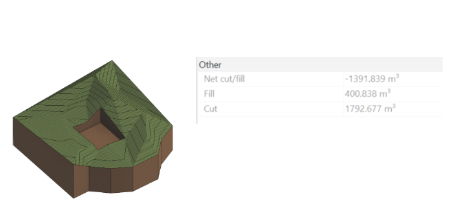
2.3 Voids and excavations
Toposolid voids and excavations can be created using an in-situ component that is a void or with a mass, converting it to a void form. Once the desired void geometry has been modeled, the target toposolid can be cut with this void.
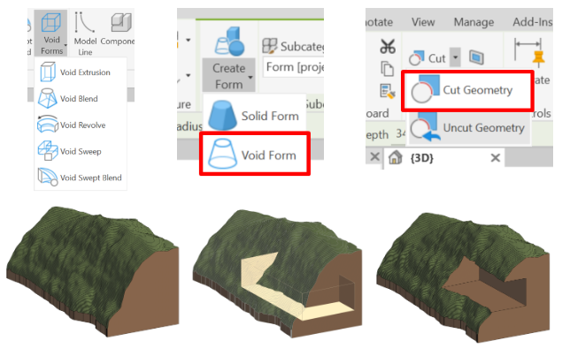
Toposolids can also be cut with elements that interfere with it, such as the foundation of a wall. The process is the same as with void geometries, with the option to cut geometry. This cut is also available with geometries imported from a CAD. These cuts affect the calculation of material removed from the toposolid.

2.4 Appearance of contour lines
In toposolids, the display of contour lines works by type of toposolid and not in a generalized way in all the elements of this category. In order to modify the graphics of the contour lines, it must be done from the type edition.
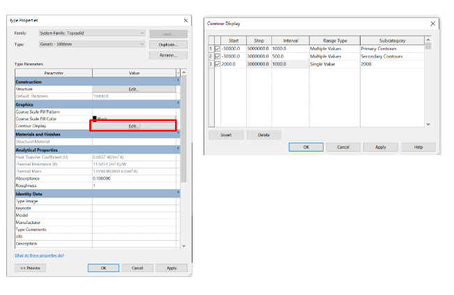
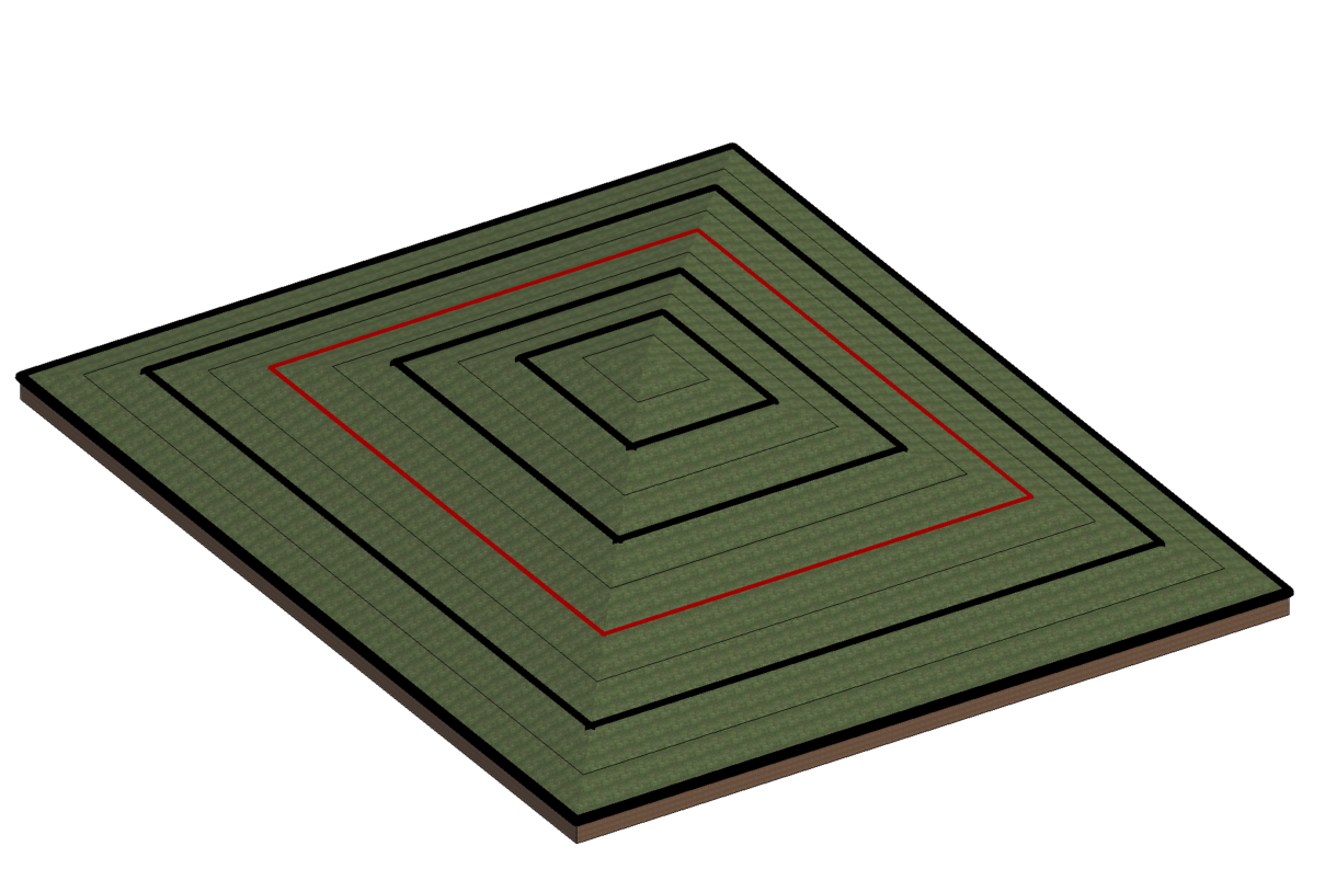
The curves are represented according to the subcategory assigned to them. You can also adjust the start and end elevation or if you want to show only one contour line or more than one at a specific elevation. The display of curves can be activated and deactivated by checking or unchecking the box on the left respectively.
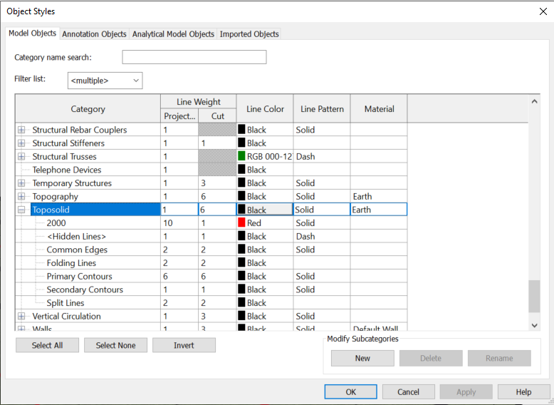
The display of the subcategories can be modified directly in the graphics of the view itself or manage the line styles from the object styles window within the toposolids section. You can also create new types of lines apart from those that come by default.
2.5 Toposolids as a host for other elements
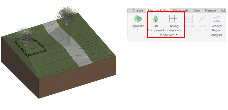
Toposolids can host multiple categories. Site components, parking components, ground-based families and railings can be applied with it as a host. The “slab edge” option only works when the profile of the toposolid is flat, although you can later modify the sub-element that affects the “slab edge” and it tilts following the profile of the toposolid.
3. Phases of toposolids
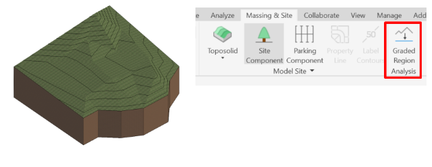
With the toposolids Graded Region tool it is possible to keep track of any changes that may occur in the topography during the project or construction phase.
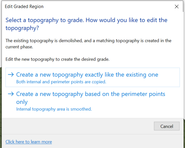
To carry out this monitoring we must start from a toposolid that reflects the state of the topography of origin. When selecting the Graded Region tool, the message will appear to create a toposolid exactly the same as the original or reset its interior subelements and only keep those on the perimeter.
The initial toposolid creation phase must be set to Existing so that the resulting amount of cut and fill after all modifications appears in the project's modified topography.