
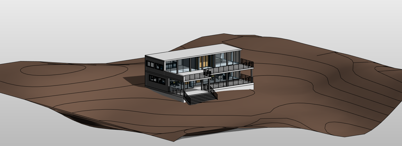
Topography
Operation in Revit
Topography in Revit
Objectives
- To understand how the topography works in Revit.
- To understand how phases work to get the volume difference between cut and fill.
Prerequisites
- User will be using Revit, any version.
- User has basic skills in modelling and how phases work in Revit.
- User has basic knowledge in Autocad.
Associated Files
- PRC_TopographyAndPhasing
- MOD_TopographyIntegration
- WFW_RevitCoordinates
- OPE_Phasing
Description
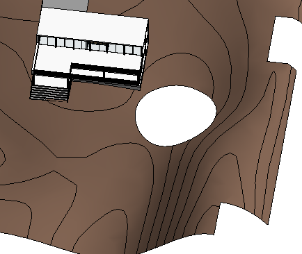
The Toposurface tool defines a topographical surface using points or imported data in CAD format.
The topography tool is not the strongest point of Revit, because it is not very precise and it works properly only for certain typologies of projects. In other words it is not the tool for accurate earth-moving projects. However it is enough for basic operations in the context of building projects.
Sometimes, the best solution is to generate the surface manually in Revit, sometimes to generate it based on imported data, sometimes simply import the surface from another more appropriate software (Autocad, Rhinoceros, …).
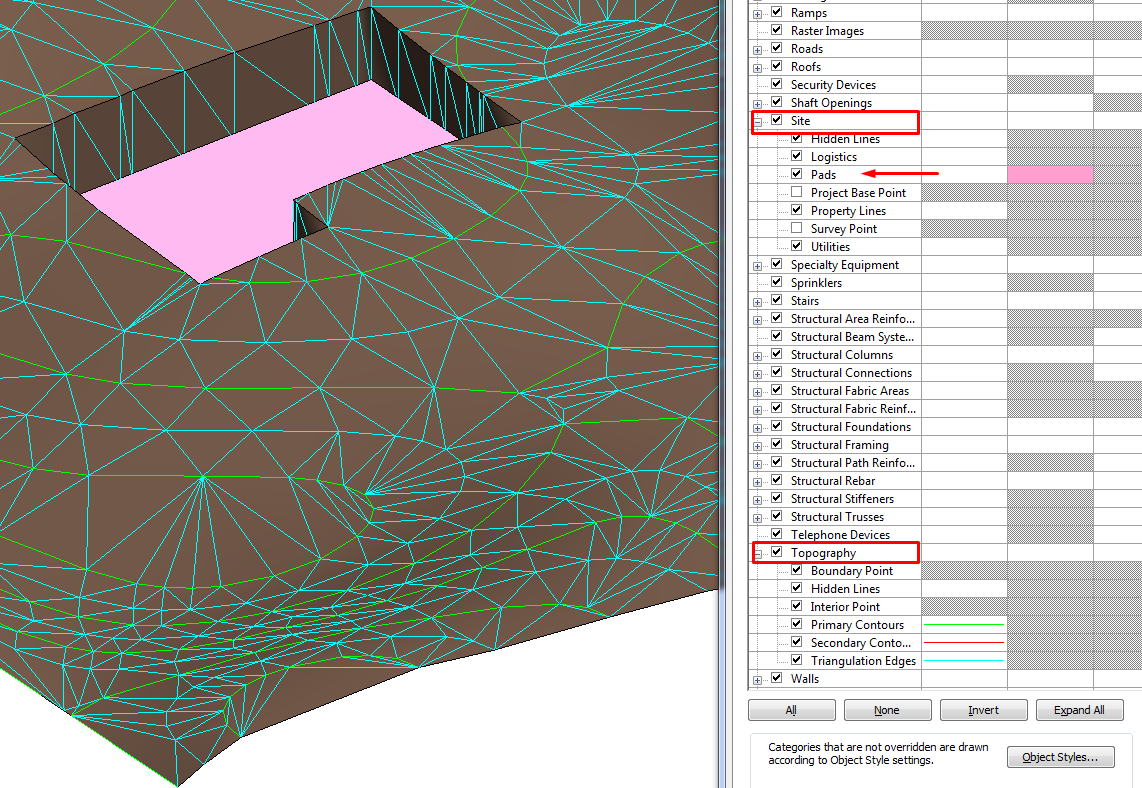
Topography is a Revit category that is complemented by other Site components (Building Pads).
Visibility
The visibility of topographic points can be controlled by using their different sub-categories: Boundary and Interior. Revit classifies points automatically.
The triangulation edges for "Toposurfaces" are turned off by default. Their visualisation can be turned on by selecting the corresponding subcategory from the Model Categories/Topography category in the Visibility/Graphics dialog.
Procedure
Create a new topography by placing points
With this tool points can be placed as necessary, want with different elevation settings:
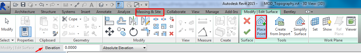
Absolute Elevation: point elevation is displayed related to the Project Base Point. Points can be placed anywhere in the active drawing area.
Relative to Surface: when editing a "Toposurface" additional points can be added on it. Selecting the option “Relative to surface”, the specified elevation will be related to the existing "Toposurface". To use this option effectively, it is better to work in a shaded 3D view.
Modifying the surface points can be added any time needed.
Create a topography from an imported CAD
Sometimes the source information will be a CAD drawing with contour lines (elevation curves) or points describing a topographical surface.This information can be used directly to generate a "Toposurface" inside the Revit model, following the procedure described below:
Link the dwg file. Select the correct positioning option. (See Coordinates Guideline).
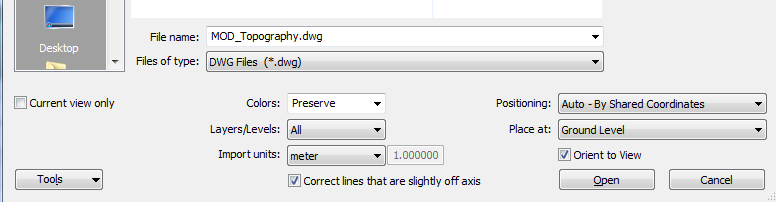
Work in a 3D view for this procedure. On the Modify/Edit Surface tab, click Tools panel > Create From Import drop-down (Select Import Instance).
Select the link in the drawing area.
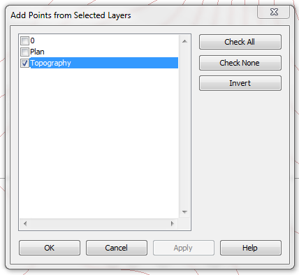
Select the layers to which you want to apply elevation points. Revit will automatically add a point in each vertex of the contour lines. Click on the green check button.
Create a new topography from a points file
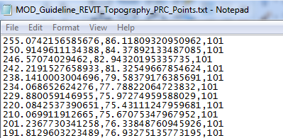
A points file is typically generated by a civil engineering software application. The file provides contour data using a regularized grid of elevation points.
The points file must contain x, y, and z coordinate numbers as the first numeric values in the file. The file must also be in a comma-delimited file format (a CSV or TXT file). Additional information in the file (such as a point name) is ignored. Any additional numeric information for a point must occur after the x, y, and z coordinate values. If the file contains 2 points with the same x and y coordinates, Revit uses the point with the largest z value.
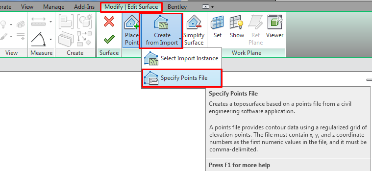
In the Format dialog, specify the units used to measure the points in the points file.
Revit generates points and a "Toposurface" from the coordinate information in the file.
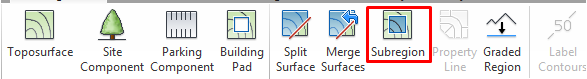
Surface tools
Simplify surface
Each point in a "Toposurface" creates triangulated geometry, which adds to the computational overhead. When a "Toposurface" is created using a large number of points, it can be simplified to improve system performance.
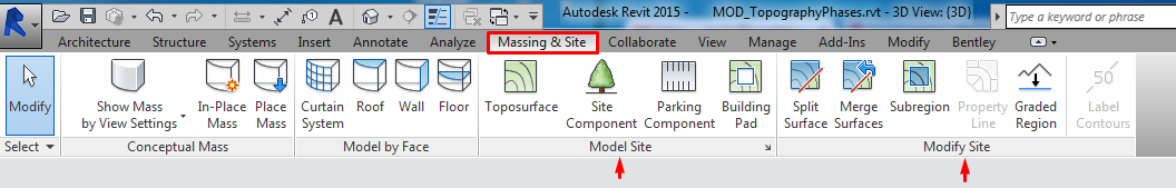
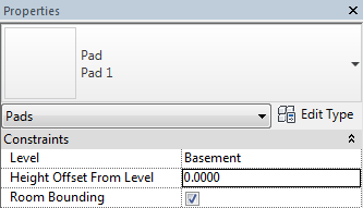
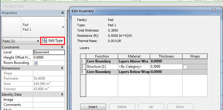
Create building Pads
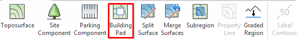
When a topography is created and the building is placed in the correct spot, if the building and the "Toposurface" intersect the terrain is going to invade the inside of the building.
To avoid this from happening the terrain should be cut to the limits of the building by using the “Pad” tool. A building “Pad” can be created by sketching a closed loop on a "Toposurface" in a similar way as floors are created: after sketching the “Pad”, height offset from the level and other properties can be controlled, openings can be defined in the "Pad" by sketching closed loops inside its perimeter, and a slope can be added for the building "Pad".
As said, for most of the features it works like the floor tool.
Click on Massing & Site > Model Site > Building Pad, making sure that in the Properties panel the Level and offset desired are selected..
Draw the perimeter lines for the platform and click on the green check.
Structure: The procedure to define the structure of a building "Pad" is the same as in a generic floor. Select the "Pad" > edit type properties > structure > insert layers.
Some remarks to the building "Pads" in "Toposurfaces":
Building "Pads" will cause the "Toposurfaces" to cut or fill depending on the relative position (elevation) of the "Pad" in relation to the "Toposurface".
The cut and fill of the "Toposurface" will be always vertical, no other angle can be defined. This could only be achieved by by editing manually the surface points.
The cut in the "Toposurface" will be always all through the "Toposurface" from top to bottom (depending on the “Pad” position). This means that holes like similar to tunnels with some height of terrain covering the cut can not be created with the “Toposurface” tool.
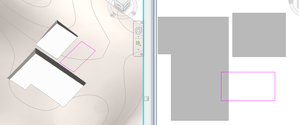
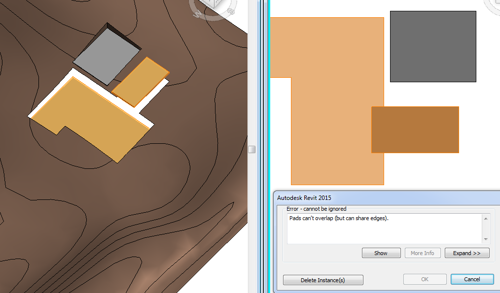
Two building "Pads" cannot share a portion of surface. They can be adjacent but they cannot be overlapping.
And “Pads” must be totally inside the “Toposurface” perimeter. They cannot be partially inside and partially outside.
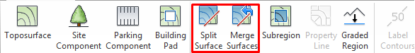
Split Surface
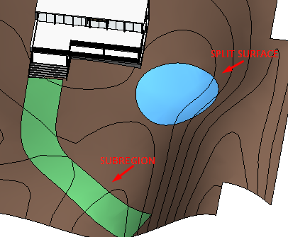
A "Toposurface" can be split into two (and each into two) distinct surfaces and then edit those surfaces independently. After splitting a surface different materials can be assigned to them to depict roads, lakes, plazas, or hills.
The Split Surface tool can be used to remove unwanted portions of a "Toposurface" generated by an imported file. Split surface boundaries can be deleted but not subregions (see following sections).
If the Phase Demolished property of the "Toposurface" is set to a value other than None and you then split the "Toposurface", this value will be changed to None for one of the resulting surfaces.
Sketch a single closed loop that does not touch boundaries of the surface, or sketch a single open loop. Both ends of an open loop must lay on the boundary of the surface.
Merge Surfaces is useful to rejoin splitted surfaces. The surfaces to be merged must overlap or share a common edge: on the Options Bar, clear Remove points on common edges. This option removes excess points that were inserted after a surface was split. The option is selected by default.
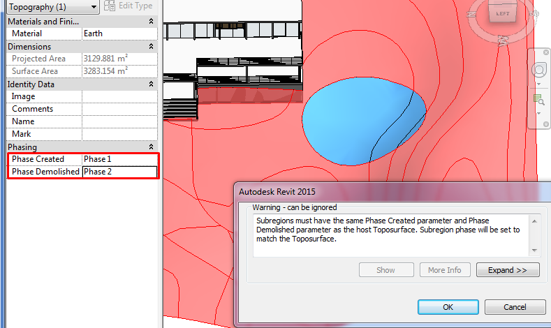
Subregions
Toposurface subregions are areas that you sketch inside existing "Toposurfaces". They are usually used to differentiate roads, paths...It merely defines an area of the surface where you can apply a different set of properties, such as material.
Use a single closed loop to create a "Toposurface" subregion. If multiple closed loops are created only the first loop is used to create the subregion; the remaining loops will be ignored.
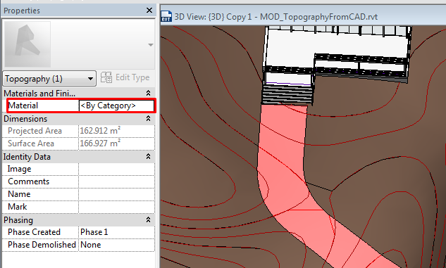
If the Phase Demolished property of the topography is set to a value other than None, the subregion will change to match its host.
Property Line
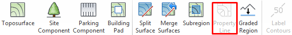
To create property lines can be created directly with the sketching tools in Revit or enter survey data directly into the project.
Property lines are annotation objects that we only visualize in 2D views such as plan views.
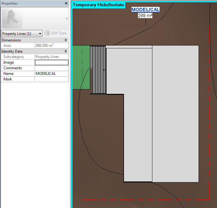
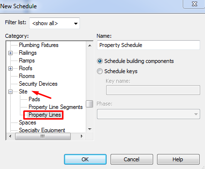
Scheduling. Property lines can be scheduled. The schedule can include the Name and Area property line parameters.
Tagging. Property lines can be tagged and can report surfaces in square meters.
Load the tags from the Annotations > Civil folder of the Revit family library. The tags is M_Property Tag.rfa.
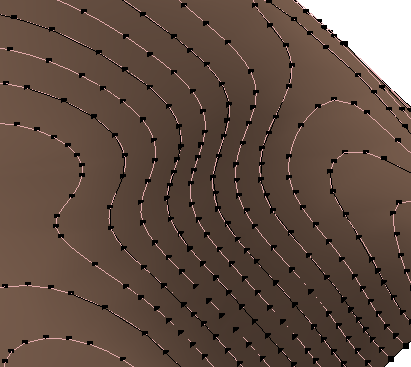
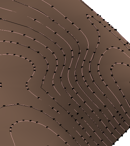
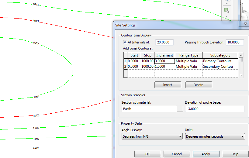
Site Settings / Label contours
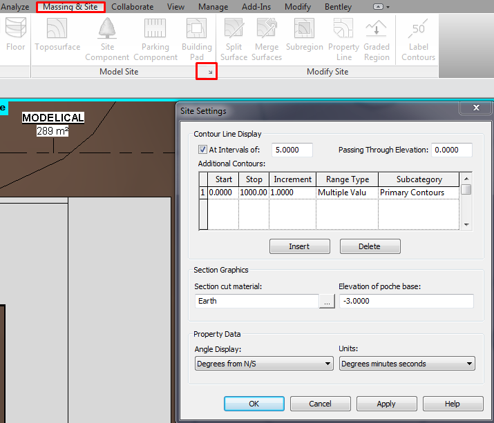
At Intervals of: Displays contour lines. Clearing the check box will still display custom contour lines in the drawing area.
Passing Through Elevation: Contour intervals are based on this value. For example, setting the contour interval at 10, contour lines display at -20, -10, 0, 10, 20. If the Passing Through Elevation value is set to 5, lines display at -25, -15, -5, 5, 15, 25.
Additional Contours: Sets the elevation where additional contour lines begin, end, the interval. The subcategory that the lines will take can be also defined.
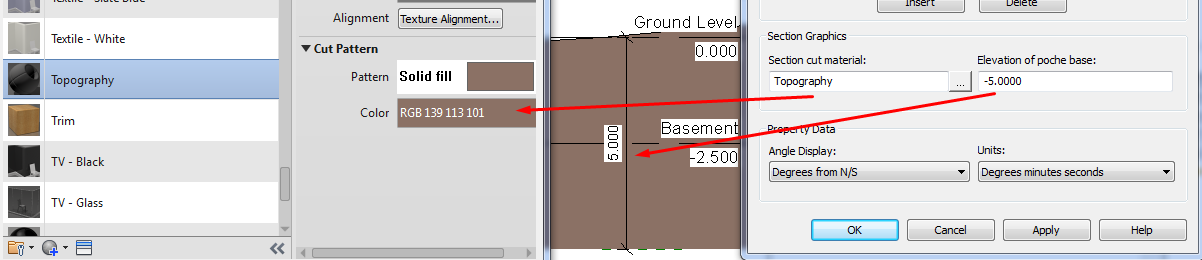
It is also editable the default material the topography will display.
The last section is about property data. It shows the angle and units format the property lines annotations will display.
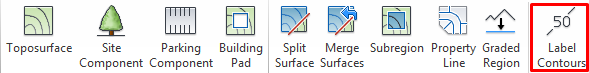
The contours can be tagged with the label contours tool. It is a line that shows the elevation of the contours it intersect (zoom in to see the labels). The label line itself is not visible unless a label is selected.
Its appearance can be changed like everything in Revit, by editing its type.
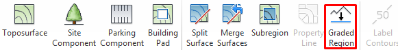
Graded Region
This tool is useful if to quantify the amount of terrain moved out/added to build theproject. To do so it is necessary to work with phases and graded regions to make a comparison between the original terrain and the modified one.
Revit can report cut and fill volumes on a site to aid in determining the costs of landscape modification during site development.
Revit reports the values by making a comparison between two surfaces from different phases that share their boundaries.
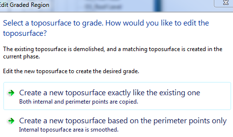
To create a graded region, a Toposurface should be selected and set to the Previous phase. When using the Graded Region Tool Revit marks the original surface as demolished and makes a copy with a matching boundary. Revit marks the copy as new in the current phase. The process is as follow:
Name correctly the existing topography and define its phase.
Create the graded region > Select Create new "Toposurface" exactly like the existing one. Change it name and finish the action. Take care of the phase filter of the view.
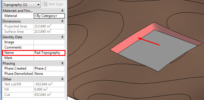
Once the existing and the new topography are in place (created by the Graded Region tool), the new one can be modified in any way needed (adding "Pads", editing the points manually). It is important to make sure that all the Toposurfaces have the correct name (including the vertical surface created with the "Pad") to clearly identify everything in the schedule.
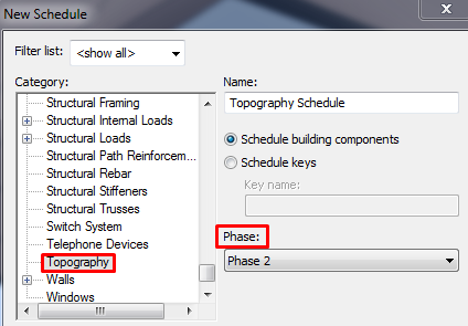
Now it’s time to make a new schedule to calculate the volumes.
Go to View > Create > Schedules > Schedules/Quantities and make a new schedule for Topography category in the correct phase (the newest).
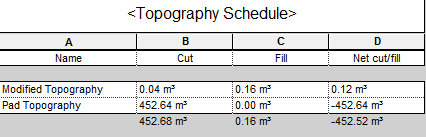
The cut and fill volumes calculated by Revit are approximate, generally providing results with +/- 1% to 2% accuracy.
After adding a building "Pad" to a graded surface, you will see “cut and fill” reported separately for the "Pad" and the "Toposurface" in a topography schedule. This is because the "Pad" divides the graded surface into 2 surfaces: one is the surface under the "Pad" (the graded surface), and one is the surface that is not under the "Pad" (the "Pad" surface).
Both the graded surface and the "Pad" surface should be named correctly for better understanding of the information in the schedule.
Tips&Tricks
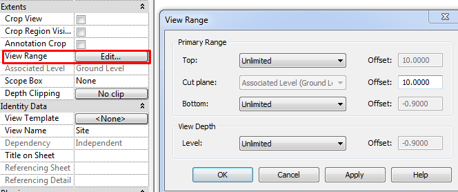
The best way to create a topography is to work in a view with unlimited view range, thus always visible regardless of height. Templates by default displays a view with the name SITE prepared for this purpose, you can create if it doesn't exist.
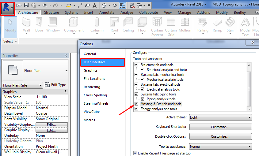
The topography is generated from the Massing and Site tab. It is possible that this tab doesn't appear. You can activate it from the Options button in the application’s menu (User Interface / Tools and analyses).


Bottom-line
Revit can manage to work with topography in a project although it isn’t its strongest point. It is normally used just for visual effects and get estimation about cut/fill volume. To get more accurate data and complex cut/fill geometry operations you should use other softwares like Civil3D.
Es bastante interesante el tema gracias
Excelente, muchas gracias y felicitaciones por el aporte !!!!
BUENA METODOLOGÍA