

A short introduction to 3D Coordination
Much more than detecting clashes
The quintessential BIM use
Are the generated models coordinated? What is a coordinated model? These are questions we should be asking ourselves in each and every BIM project we face, otherwise , we will not be delivering quality models.
In this post we will analyze the main BIM use that all projects must address: 3D coordination. It is indeed one of the reasons why projects are being done in BIM…
We develop BIM models to have a clear vision of the project as a whole, but there are boundary conditions that prevent us from having it:
Isolation may be the most problematic issue. By ensuring collaboration and access to information from other teams we make coordination much better. It is an error to think that by having all the models loaded in real time with all the teams involved, we will have a coordinated model. In fact we probably have more noise that affects the decision making.
On the other hand, noise is what generates most fear in the design teams when sharing their models. They are reluctant to collaborate in real time because of the impact their models may have on others. Periodic publication for model federation mitigates this effect when it comes with some cleaning and purging instructions.
A federated model is several models aggregated into one. It’s the most complete image we can have (at any given time) of the project. It’s a single model that has inside all others within and does not need them to be executed. The term “frozen BIM model” is used to indicate that you will not work anymore in a “work in progress” model. It would be rare to use it as a synonym of federated but you can find it out there. We could say that a federated model is generated from frozen models in order to submit them to coordination analysis.
This doesn’t mean that we should not take coordination into account when modeling. We have to take into account only the necessary elements that guarantee that our instances are coordinated. For this reason it is necessary to establish a hierarchy.
Planning for coordination
What we are going to coordinate is just as important as defining what is not going to be coordinated. The scope of the coordination is crucial. Clash-free models are unicorns, they are always clash-free with respect to certain rules and tolerances and not others. It’s fundamental for the design teams to know how the models are going to be checked in order to model consequently.
We usually find the following ways of planning the coordination that have to do mainly with the different scopes and deadlines:



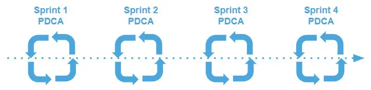
The most common scenario is to work with periodic review milestones. It’s necessary to define these milestones in order to have all the required elements modeled and also to ensure that after the review the resolution of the failing items is made. It’s important to give continuity to the checks, so these models have to be cumulative, this is that in the following check the previous one is checked again. Each revision must complete a PDCA cycle autonomously, sprint-based schedules work very well in this context.
The layers of the following pyramid represent different levels of coordination. It is necessary to solve the problems at the base before being able to solve the upper layers. A disciplinary coordination must be carried out between layers in order to start the interdisciplinary coordination.This means that we have to undertake first STR against STR and ARC against ARC and after that we can do STR against ARC…
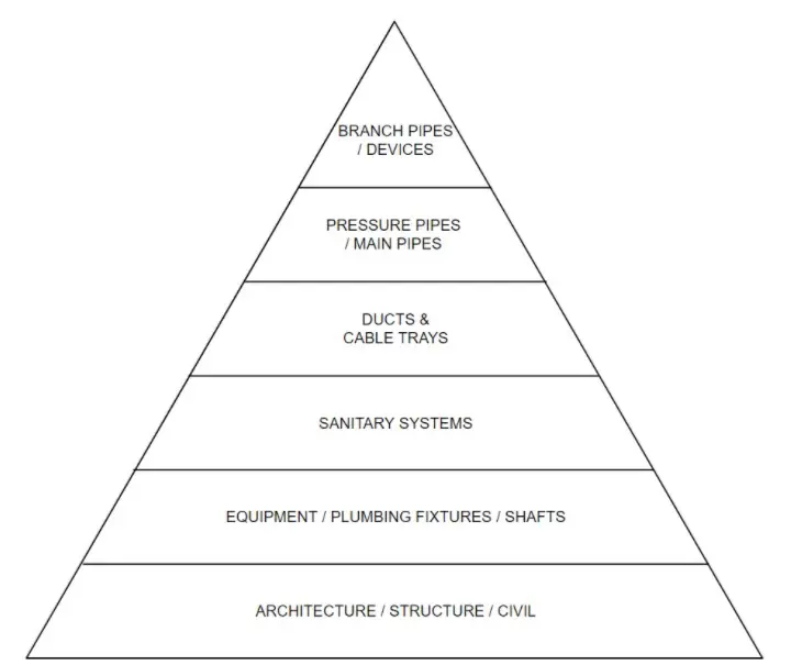
The following list is a slightly more detailed version of the pyramid:
- Elements of the current infrastructure/state model, existing elements, roads, sidewalks, municipal networks.
- Elements of the structure model.
- The permanent elements (neither furniture nor finishes) of the architectural models
- Technical rooms and skates, base equipment and sanitary devices.
- Terminal equipment and coordination in false ceilings (lights, sprinklers, air terminals…)
- Gravity piping networks, drainage, condensate… are the least manoeuvrable.
- Air ducts, especially large ones, and connections in technical rooms.
- Cable trays, taking into account the tension that circulates through them (first medium, low and finally IT trays).
- Pressure pipes and main branches.
- Branches, connections and devices.
With this hierarchy the different coordination milestones can be scheduled. The clash matrix is always helpful here.
The clash matrix is a table showing the checks to be carried out in the different phases of coordination. It should indicate the set of elements to be analyzed but also what is not going to be analyzed. It includes information about priorities and check dates.

In this image you can see how each set of categories (column D) represent search sets (column C) for the clash detection program, also a priority (column A) is assigned for each one, going from 1 (high) to 89 (low), then the table makes automatic assignment to the checkpoints (H,M,L), leaving out a good bunch of irrelevant clashes (0).
Clash types
We can classify the types of clashes according to the nature of the clash in terms of space and time:
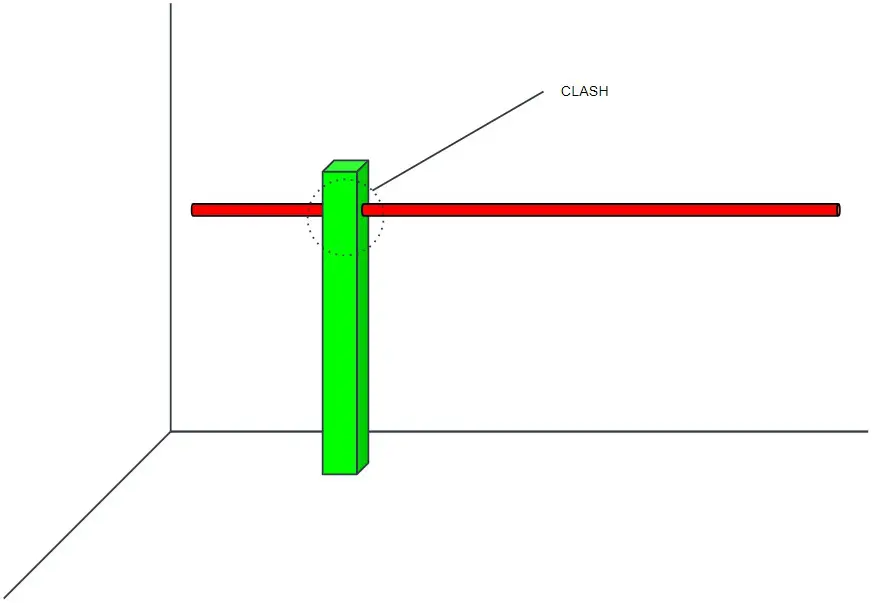
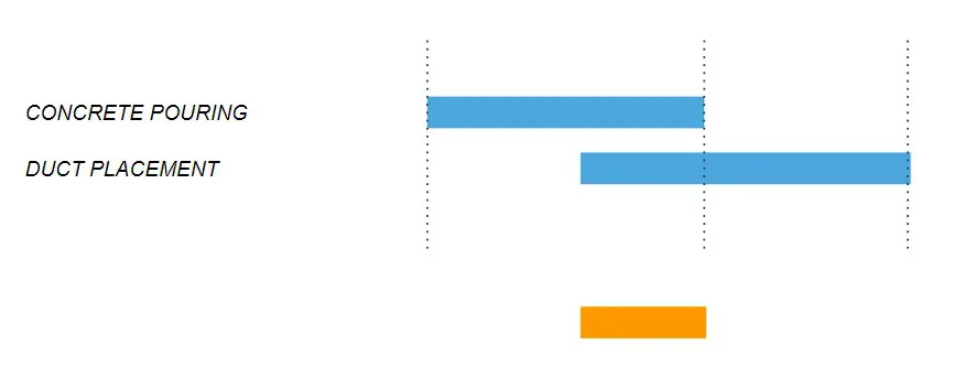
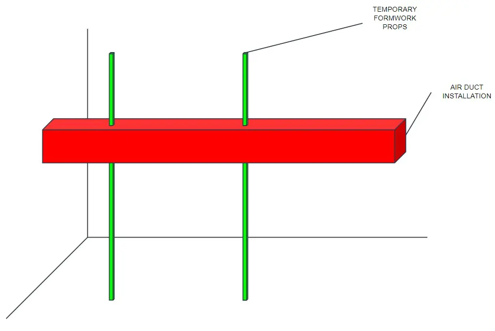
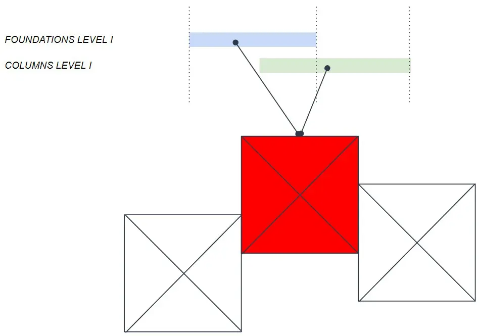
Workspace clashes: Generated by the overlap of two workspaces that cannot be performed at the same time in the same place. Understanding a workspace as a spatial element (room, space, area, zone…) associated with a manpower resource. For example, foundation elements at the same space and time than their corresponding column elements. They come from model-based scheduling.In these analyses it’s crucial previously to have linked spaces with tasks and to have divided the workspaces into parts following Lean 5S principles.
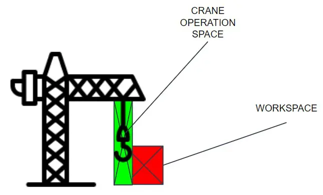
Routes and lifting clashes: When we move material or an equipment from one place to another or when the risk space generated by the operation of some resource or auxiliary elements clashes with workspaces or installed elements.
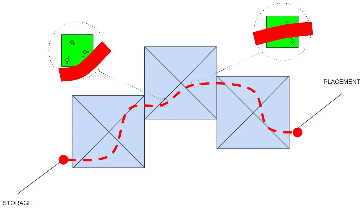
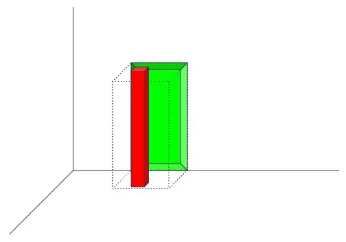
To clash is as important as not to clash. That is why it’s also sometimes useful to establish a classification according to the result of the analysis:
Negative clashes are useful for example for checking the existence of elements in spaces. It’s like saying: these elements must clash with these ones, if not, please, highlight them. For example, check the climate rooms that haven’t got (don’t hard clash with) drains, or that a certain type of room always (does hard clash) must contain certain types of ceilings or ensure that near certain elements (do soft clash) there must be others.
Coordinate = Detect + Resolve
As per Deming’s Plan-Do-Check-Act cycles, we must ACT somehow after a CHECK. We cannot say that a model is coordinated because we have attached a clash check. To coordinate is to detect, but also to resolve.
Rule of thumb: an issue is solved sooner if it’s easier to consume by the person who has to solve it.
To facilitate this we have tools to streamline the consumption of clashes once generated in the corresponding BIM authoring tools, but the best thing without any doubt is to have a workflow that fits in a common
To plan how to generate the clashes/issues it’s best to keep in mind how people are going to consume them. That state of mind will give us the answer not only to how to generate them, but also to how to group them and to transmit them.
Clash detection software
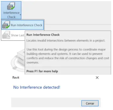
Revit interference check
From Revit OOTB we can dynamically resolve clashes between models at the category level, even with linked models. It’s a great tool for disciplinary coordination, but also a first approach to interdisciplinary one for people who model. It’s just a click away and takes you to the view where the clash is.
Navisworks Clash Detective
What to say about old Navis! It’s a great model aggregator. It usually comes in Autodesk’s Building Design Suite with Revit, like those movies that appear in the billboard with the blockbuster but this one is worth watching. As a tool for making “Hard Clash” detection it’s especially good. Something special that not everyone knows (like many other things in Navisworks) is that you can perform point cloud clash detection, very useful for installing new elements in existing buildings.

Solibri Check Rulesets
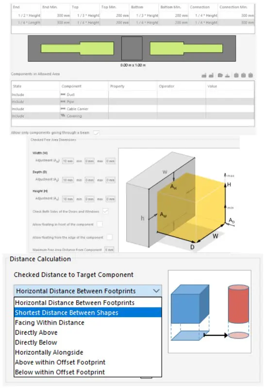
As a tool for detecting soft clashes is unsurpassed, it’s good in dribbling false positives, discriminating between different directions or types of clash beyond the properties of the elements. It’s also extremely useful for checking compliance with standards. The only drawback is that it only eats IFCs, so it can’t compete as a model aggregator. In the image below we can see how we can set valid pass through zones for clashes with beams, clearance spaces in front of elements and different types of calculations of distances between elements.
Synchro Dynamic Clash Detection
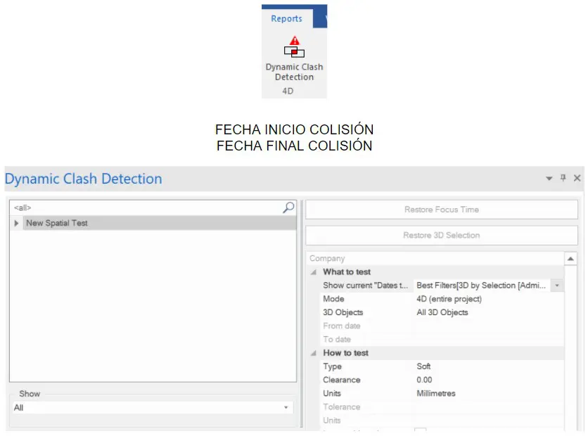
The way to go if you want to do 4D clash detection. Already as a planning tool it leaves Navis Timeliner in another level, getting closer to the classic planning tools like MS Project or Primavera in terms of schedule calculations and tasks relationships, but it also allows to divide geometry and it’s a great model aggregator. The main tool for Model Based Scheduling has sophisticated tools to manage workspaces and associate them to animations that also make it the best option when simulating routes and lifts.
Conclusions
Each tool has its own use and function. If we want to generate a workflow that is aligned with the software it is necessary to know the details of the tools in advance , so test them before designing a coordination plan. We cannot have everything under control, but we can control the most important things, which are those that generate more problems. Test always with soda, in other words, test new tools in controlled environments. We must first know the classic solutions in order to avoid reinventing the wheel again and again.
I hope you found this interesting and informative. Thank you very much, if you have reached this point please leave a comment expressing your opinions, it’s always a great day to learn something new from professionals like you.
Author: Julio García