

Adaptive Components
Operation in Revit
Adaptive Components
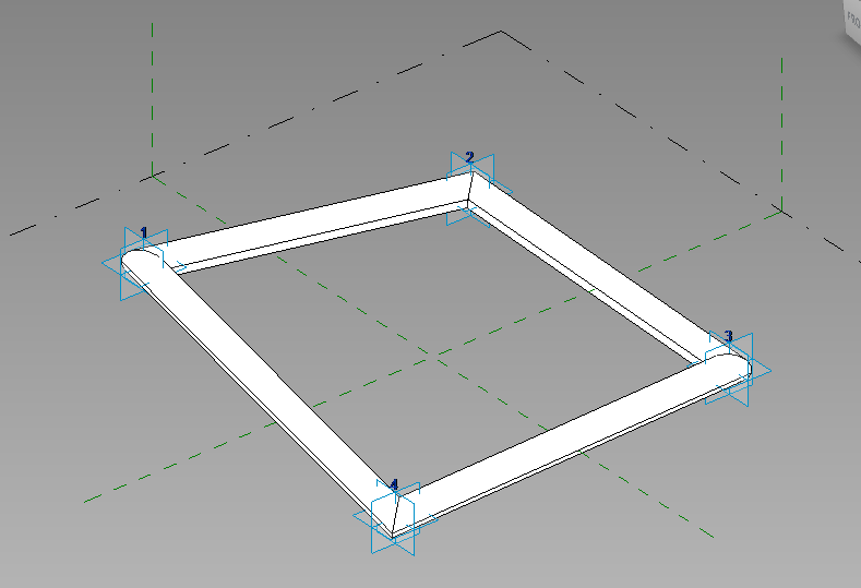
Objectives
- Learn what is an adaptive component.
- Learn how to create adaptive components.
- Learn when is better to use adaptive components instead of other family types.
Assumptions
- The user will be using Revit 2019
- The user has correctly installed Revit´s Family Templates
- The user knows how to create families.
Description
Adaptive components are mostly used when there is a need to adapt a family to different positions in space following parametric rules.
A special feature is that, while in regular components (families) the geometry of the family is related to one unique insertion point (or two for line based families); in adaptive components it can be related to more than one insertion point. In this way, the adaptive component can grow differently depending on the specific position of those points.
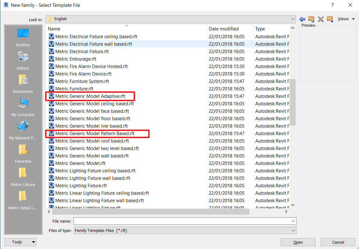
There are two types of family templates for creating adaptive components:
- Metric Generic Model Adaptive
- Metric Generic Model Pattern Based
The key aspect of the adaptive components is the definition of the adaptive points. The geometry drawn by snapping to these flexible points results in an adaptive component. Adaptive components can be used in pattern panel families, adaptive component families, conceptual massing environment and projects.
Advantages of adaptive components
Adaptive components are a powerful tool because they allow us to create dynamic adaptive components in Revit. This means that we can have infinite forms of a family without having to have infinite types of family with different parameter values. Each instance will adapt according to the position of its adaptive points. Because of the adaptive component smart nature, its applications are endless.
Disadvantages of adaptive components
Adaptive components do not have any 2D or 2½D capability - there is no Annotation tab in the adaptive family editor.
- No text within Adaptive Components
- No symbols
- No symbolic lines
- No detail components
- No filled or masking regions within Adaptive Components
Procedure
1 Choose family template
Select the Family Template to create the adaptive component, either “Metric Generic Model Adaptive.rft” for generic models or “Metric Generic Model Pattern Based” for patterned panels.
2 Make adaptive points
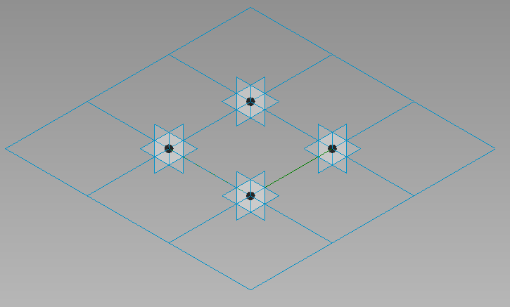
Adaptive Points are modified reference points that are used when designing an adaptive component in the conceptual design environment. In the “Metric Generic Model Pattern Based” template, adaptive points are already created in a square shape.
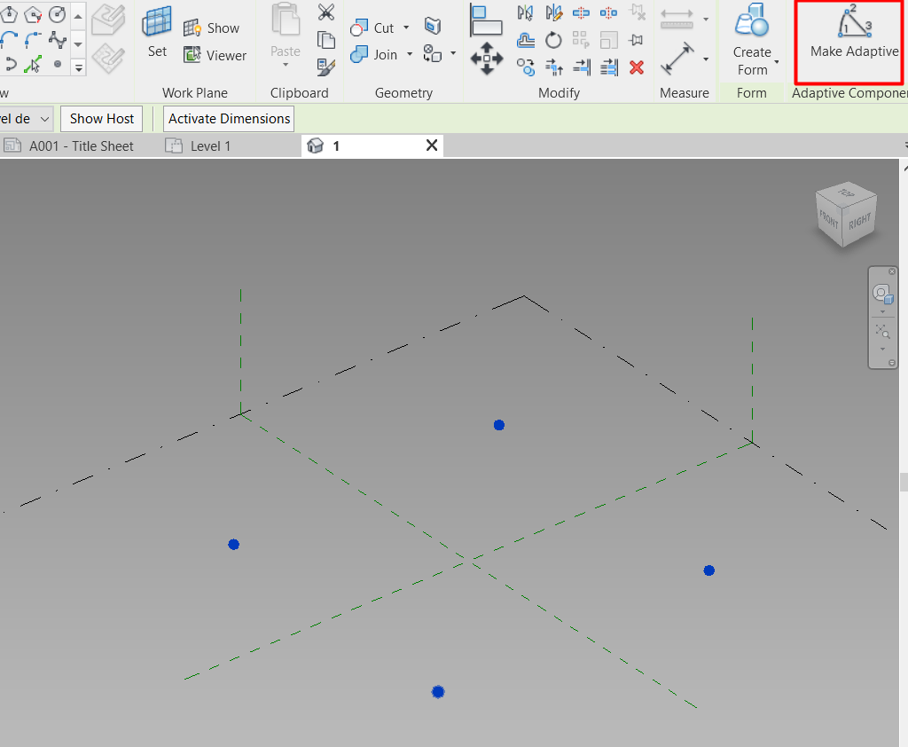
In the “Metric Generic Model Adaptive” template, Adaptive points can be created by the user. Adaptive points are created by inserting some reference point and making them adaptive in a generic adaptive family. When a reference point is made adaptive, it has a placement point by default. The adaptive points will be numbered in the order in which they have been placed. Geometry drawn using these adaptive points results in an adaptive component.
If you need to change the order of the numbering you can pick on a number, change it, and the others will adjust accordingly.
3 Create geometry
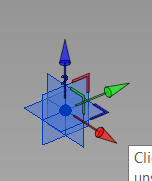
Before modeling any piece of geometry, we have to know that each adaptive point has an X, Y, and Z work plane.
To start creating a surface, make sure 3D snapping is turned on and draw a Reference Line from point to point. To do this, pick the Create/Modify Tab > Model Lines / Reference Lines and turn on the 3D Snapping from the options bar.

What is the difference between choosing Model lines / Reference Lines?:
- Model lines: They are actual lines or edges that will appear in the model when the family is loaded into the project.
- Reference lines: They are reference elements that have no visual entity when loading the family into the model, but are a good basis to create geometry. Besides they have four associated work-planes, two intersect in the longitudinal dimension and define the line. Other two are perpendicular to the line at its ends.
Choose in each case the line that best fits the purposes of the component.
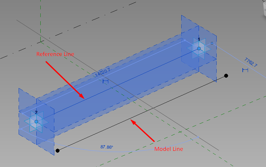
Draw model lines in the order of the reference point numbers and make sure that the lines are linked to the adaptive points.
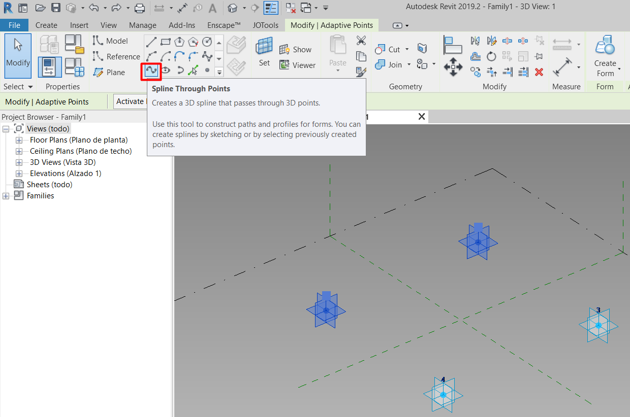
Sometimes it can be difficult to link properly the lines to the points. In that case, we can proceed by selecting two points and choosing the “Spline through points” tool. The line will be automatically attached to the points.
- If we select only two points we will get a straight line.
- If we select three or more points we will get a spline (curve) through the points.
The reference line will follow the adaptive points wherever they move.
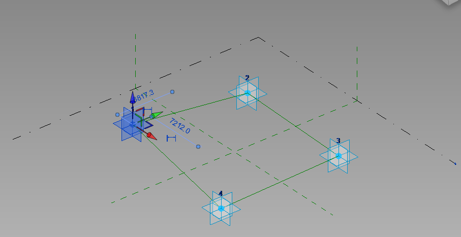
When you have a closed curve, you will be able to convert the lines into a surface or a solid form by clicking the “Create Form”.
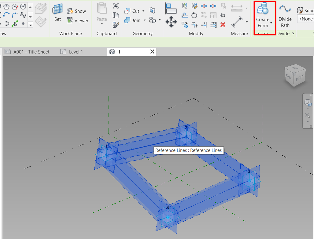
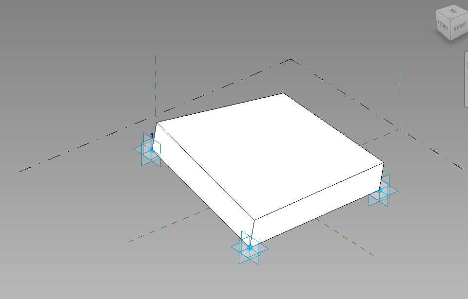
Depending on the input data we will be able to create different types of geometry based on the adaptive points.
If we place a reference point in some of the reference lines and draw a circle in the perpendicular plane to the line we will get a sweep when applying “Create Form” to the circle and the reference lines.
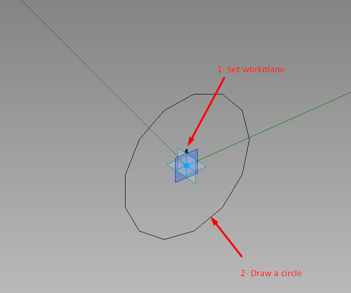
Although in Adaptive components (same as in Conceptual Masses) we do not find the “Geometry Tools” buttons from a regular family, such as Extrusion, Sweep, Blend, etc.; the “Create form” tool uses the same logic. For different data inputs:
- Closed loop > We get a surface or an extrusion
- Path and cross-section profile > we get a sweep
- Path and various cross section profiles > we get a sweeping blend
- Two parallel but different profiles > we get a blend
- An axis and a profile > we get a revolving
- We can get the same solid and void forms and make boolean operations.
4 Reporting parameters
When we create a parameter in an adaptive component we have to set a reference plane that contains the dimension line. It is important to take into account that if the parameter is going to give information related to the adaptive geometry, and therefore it must be a reporting parameter.
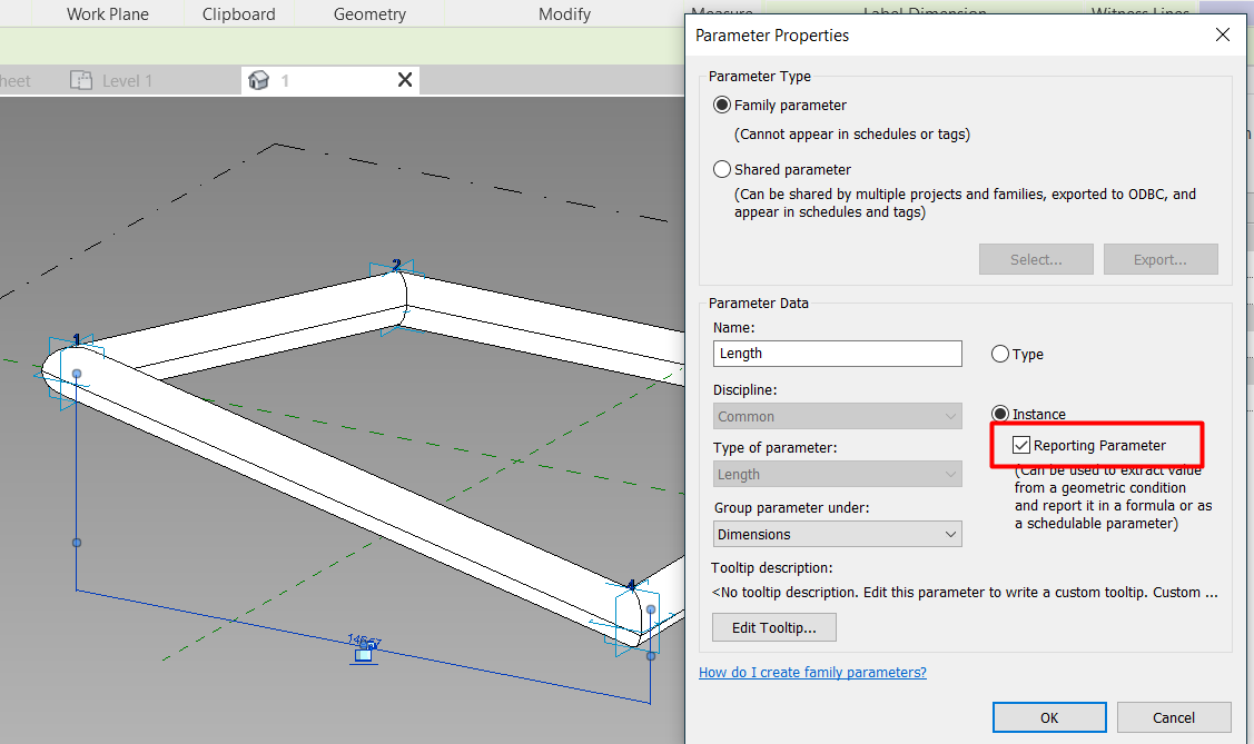
A reporting parameter is a parameter type that has its value driven by a particular dimension in the family model. Reporting parameters extract a value from a geometric condition and use it to report the data to a formula or as a schedulable parameter.
The reporting parameter can read the dimension of a geometry from an adaptive component so it will give different values for different adaptive components. If the parameter is not a reporting parameter, when we read the information of the parameter the value will always be the one by default (the one that was first given when creating the Adaptive component).
5 Applying Adaptive Components to the project
Once created the adaptive component and the schedulable parameters we can load the family in the project.
There are two different ways of placing adaptive components in a project: selecting a reference plane or a reference geometry. It is not relevant which option you choose since we are going to place points that are going to be snapped to 3D vertex in the actual geometry of the model.
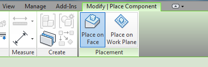
To place an adaptive component you have to select/draw as many points as adaptive points the family has.
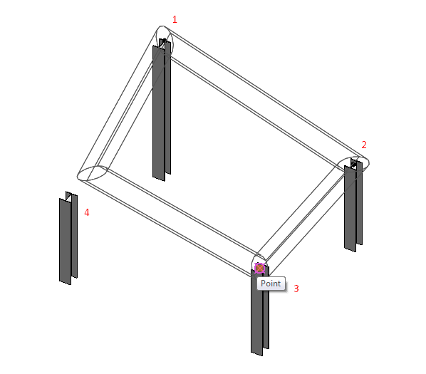
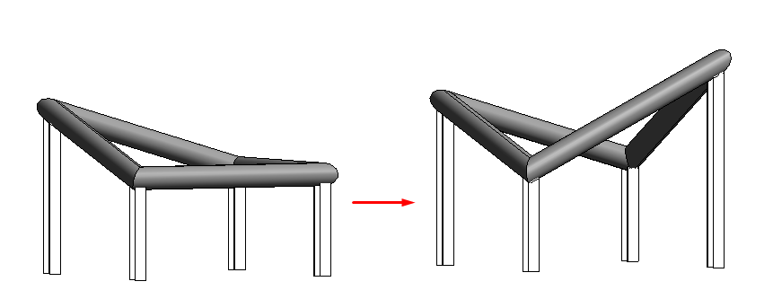
If you pick any geometry reference as a point, then the adaptive component will be related to that geometry (for instance the middle point of the base of a wall, a vertex,...). Each modification of the geometry will affect the adaptive component.
6 Nest an adaptive component in a family
This option will be advised when we need to do a family repeating an adaptive component several times.
7 Nest a family into an adaptive component
- Nest profiles: We often use profile forms to create 3D forms. When creating an adaptive component that follows an extrusion of a 2D profile, it is really useful to nest the profile (it would be a generic model face based) as a family with all the parameters that we will need to change. If we do not nest the profile and directly draw the profile using reference lines we would have to link all the dimensions to the adaptive point, which is a complex process.
- Nest 3D families: we can nest entire 3D families as part of our adaptive component. They should be placed upon a work-plane. It can be either the work-planes of adaptive points or other adaptive work-planes (those from the reference lines for example) so that the inserted family changes position according to the placement of the adaptive points.
- Nest adaptive components: we can work in cascade and insert adaptive components into other adaptive families components.
When we nest a family into an adaptive component we can nest also the nested family parameters (See Nested Families Guideline).
Tips & Tricks
- Adaptive components are mostly used when we need to adapt a family to different positions in space following parametric rules.
- To define the points in the project to insert an adaptive component, it is advisable to use Dynamo.
Bottom-line
Adaptive components allow us to create families that flexibly adapt to many unique contextual conditions. They are really a powerful tool for 3d modeling. However, adaptive components do not have any 2D or 2½D capabilities. This means we cannot do texts, symbols or detail items.
Sadly when making an adaptive component it automatically hosts itself to the lowest floor possible in our projects.
We can’t change it, nor can we give up a level parameter for adaptive families.
How should we apply a just loaded in adaptive family so that it hosts to the correct floor?
Hello Michael, as you say, when loading for the first time the adaptive family in your project it will be loaded in the lowest floor. Delete that instance or ignore it.
Now you will have the family loaded in your project and can be accessed through the project browser under the tab: Families – Generic Models. You can go to the floorplan view of the level you wish to insert your family, and drag your adaptive family from the project browser to the floorplan. You will have to place as many points as the adaptive family has and you will have your family inserted in the desired level.
Hallo Ignacio,
Unfortunately even following the steps that you mentioned the LevelId of the family instance is pointing at lowest level of the file. Do you know if it is possible to edit the LevelId in another way so that I can schedule the Level parameter of the adaptive family on a schedule?
Thank you
Hello Luis,
I don’t know about Revit older versions but if you are using Revit 2021, that’s how you should proceed:
1- Go to the desired level floorplan view, for example, Level 2
2-Select your Generic Model- Adaptive family from the Project Browser
3- Drag the family onto the canvas
4-On the tools bar, select PLacement either on Face or Work Plane
5-Below the Tool Bar there is a scroll down button with the PLacement Plane, select the desired Level (Level2)
6- Draw as many points as adaptive points the family has.
With this way, the family will be placed in the level you specified