

Coordinates in Revit
Objectives
- Fully understand coordinates in Revit.
- Understand the concept of “Shared Coordinates”.
- Work safely with coordinates.
Prerequisites
- Users have basic skills in Revit Modelling.
- Users have basic skills working in AutoCAD.
- Users have basic notions about general coordinate systems.
- Users can import/link files into Revit.
- Some notes are added to understand differences between procedures for different Revit versions
Workflow description
In Revit the coordinates work in a totally different way as they do in AutoCAD. This is why people find it so difficult to deal with them. Let’s try to explain it.
The key to the work with coordinates in Revit is the following:
When in AutoCAD we have to place something in its real coordinates and orientation, we would move the drawing and rotate it with respect to the reference system.
In Revit it is quite the opposite. We will never move, translate or rotate the model. We move the coordinate system to meet our location requirements: we will move the coordinate system origin so that our model is in the right location.
Coordinates and shared coordinates
In Revit we tend to speak always about Shared coordinates. And this is sometimes the origin of some confusion about coordinates in the Revit Models.
Instead, we should talk about:
Coordinates
when we want to refer to the coordinate system that we are using in a model, or which specific coordinates are defined on a point.
Shared coordinates
Coordinates in a file (revit or cad file) will only be shared, or the files will have shared coordinates after a process of transferring the coordinate system used in a file into another.
It does not matter if in two files the location is exactly the same. They will not share coordinates unless the sharing coordinates process has been carried out.
Normally there is one file, and only one, that is the source for sharing coordinates. From this file the location of different models is transferred to them, and after that all files will be sharing coordinates, and be able to be linked with the “Shared Coordinates option”.
Origin points in Revit
First thing to understand in Revit is how many coordinate systems we have in a project. Each coordinate system has an associate origin point, that is why it is also important to understand how many coordinates origin points we can find in a model:
There are three, and when we first open a new model, the three overlap by default. They are:
- The Survey Point
- The Project Base Point
- The Internal Origin
To show the origin points, open a plan view, go to Visibility and Graphics options > Site Category > Survey Point/Project Base Point.
Survey Point (SP – Blue Triangle)
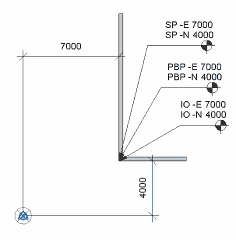
This is the point that stores the universal coordinate system, or a defined global system of the project to which all the project structures will be referred. It is displayed as a blue triangle.
And:
-
- It is the origin that Revit will use in case of sharing coordinates between models.
- The origin point used when inserting linked files with the Shared Coordinates option.
- The origin point used when exporting with Shared Coordinates option.
- The origin point to which spot coordinates and spot elevations are referenced, if the Survey Point is the coordinate origin in the type properties.
- The origin point to which level elevation is referred, if the SP is the Elevation Base in the level type properties.
- When the view shows the True North, it is oriented according to the Survey Point settings.
Project Base Point (PBP – Blue Circle)
The position of this point is unique for each model, and this information is not shared between different models. Project Base point could be placed in the same location as the Survey Point, but it is not usual to work in that way.
In general, Project Base Point serves as a local reference in projects, for each building of a complex for example.
And:
- The origin point to which spot coordinates and spot elevations are referenced, if the Project Base Point is the coordinate origin in the type properties.
- The origin point used when inserting linked files with the Project Base Point to Project Base Point option. *Option only available from Revit 2019 (included) and onwards.
- The origin point to which level elevation is referred, if the PBP is the Elevation Base in the level type properties.
- When the view shows Project North, it is oriented according to the Project Base Point.
- If it is not necessary, it is better not to move this point, so that it always is coincident with the third point: the Internal Origin.
- If we have moved the PBP to a different location, it can be placed back to the initial position by right clicking on it when selected, and choose “Move to Startup Location/Internal Origin”
Internal Origin (IO)
Not everyone is aware of the existence of this third origin point, but it is essential to know about it to understand the behaviour of Revit Models in some cases.
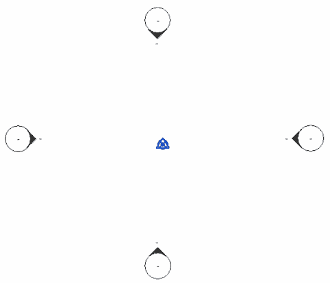
* This point is invisible until Revit 2019 (included). It has no graphical representation. When opening a new model, you will see only SP and PBP:
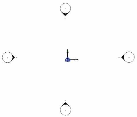
* This point is visible from Revit 2020 onwards. Fortunately it can be activated as the Survey or the Project Base point. In a new file you will see this:
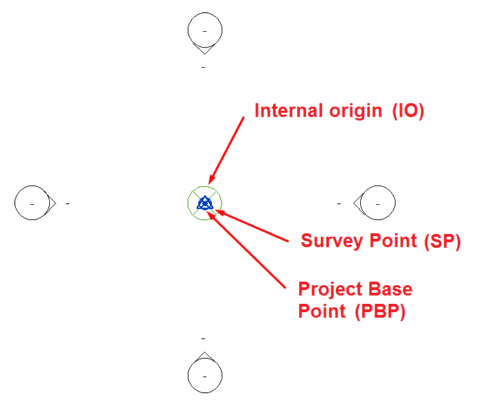
For a better understanding of this guide, we make it visible in all cases and represented by a green circle.
When starting a project the Internal Origin is coincident with the Survey Point and with the Project Base Point. Three points overlap.
The importance of the internal origin
-
- The project should be modelled in a restricted area around this internal origin point. Currently it is said that the model should be inside a 20 miles radius circle around the internal origin, so that Revit can compute the model geometry accurately.
- This is the reference point that is used when inserting external files using the “Origin to Origin” option.
- This is the reference point that is used when copy/pasting model objects from one file into another using the “aligned” option.
- When using Relative coordinates in the type properties of spot coordinates and spot elevations these will refer to the internal origin point.
- The internal origin point is used as a reference when exporting with the Internal Coordinates option.
- Revit API and Dynamo use this point as the coordinate origin point for the internal calculations.
Effects of moving the points
Let’s see how to move these origin points and their effect in our model.
Notice that we will NOT move the model elements. If we want to define correctly the project location what will be moved are the origin points, and not the already modelled elements.
We can say it in different words: we will not model objects in world coordinates, quite the contrary, we will model the building around the Internal Origin, and afterwards we define the right world coordinates of the project by moving the Survey Point/Project Base Point.
So, let’s move the points. This is the initial situation:
1. Move the Project Base Point (*until Revit 2019)
1.1. Movement performed with the PBP pinned
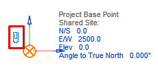
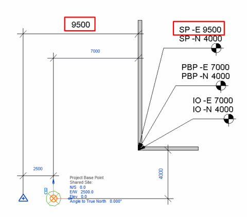
Let’s say we move the PBP 2500 units horizontally to the right:
- This is like changing the global coordinates of the whole project. Survey Point remains in the same place.
- Everything (all the model elements and corresponding annotations) except for the SP move as a block.
- We would have the same result as moving the Survey Point in the opposite direction.
1.2. Movement performed with the PBP unpinned
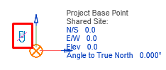
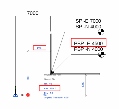
Let’s say we move the PBP 2500 units horizontally to the right, what is the effect?:
- This means just that we are moving the local reference of the project to a different position.
- No other element changes location.
- The PBP’s own coordinates change. They are related to the SP.
- Spot coordinates related to PBP change.
- Model does not change its location related to the global position or Survey Point.
- Spot coordinates related to SP do not change.
- Notice that the Project Base Point is no longer overlapping with the Internal Origin.
2. Move the Project Base Point (*from Revit 2020)
2.1. Movement of the PBP
From Revit 2020 (included) and onwards, the clip of the Project Base Point disappears. When you select it it is no longer available.
The only way to actually move the PBP now that there is no clip is equivalent to the previous Movement performed with the PBP unpinned.
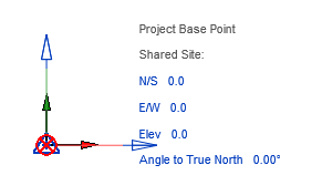
Let’s say we move the PBP 2500 units horizontally to the right, what is the effect?:
- This means just that we are moving the local reference of the project to a different position.
- No other element changes location.
-
-
- The PBP’s own coordinates change. They are related to the SP.
- Spot coordinates related to PBP change.
- Model does not change its location related to the global position or Survey Point.
- Spot coordinates related to SP do not change.
- Notice that the Project Base Point is no longer overlapping with the Internal Origin.
-
2.1. Relocate the project
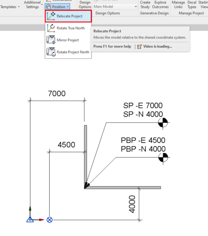
From Revit 2020 (included) and onwards, with the PBP clip disappeared, the only way to relocate the project and drag all the elements (but the SP) along with the PBP is to do it from the menu in the Manage tab > Position > Relocate Project:
2. Move the Survey Point
No differences in Revit versions for the movement of the Survey Point.
2.1. Movement performed with the SP pinned
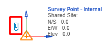
Let’s say we move the SP 3000 units horizontally to the left, what is the effect?
- This is like changing the global coordinates of the whole project. We move the Survey Point but Project Base point remains in the same place.
- No other object is moved.
- Spot coordinates related to SP change.
- Spot coordinates related to PBP do not change.
- The PBP’s own coordinates change. They are related to the SP.
- The Internal Origin does not move. It still overlaps with the PBP.
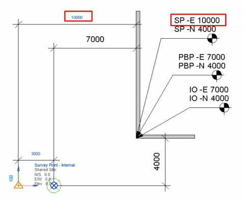
Moving the pinned PBP in one direction or moving the pinned SP in the opposite direction would have exactly the same effect in the resulting global coordinates.
2.2. Movement performed with the SP unpinned
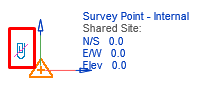
Let’s move the SP 4500 units horizontally to the left, what is the effect?
- This is maybe a puzzling option. We will move the Survey Point, but it will not have effect in the positioning of elements, understood as the assigned coordinates. The only thing that changes is the own coordinates of the Survey Point.
- We locally and visually change the position of the triangle, but let’s say that we are not actually changing the location of the global coordinate system origin point.
- Spot coordinates related to SP do not change.
- Spot coordinates related to PBP do not change.
- The PBP’s own coordinates do not change. They are related to the SP.
- The SP’s own coordinates change.
- It is as if we move the triangle, but an invisible SP remains in place.
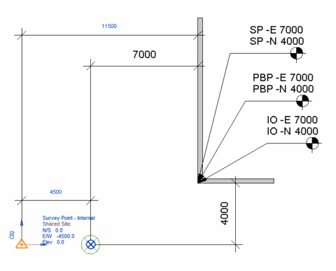
What is actually the point of this option?
This option is used to have the SP visually near to the modelled elements and internal origin, but maintain the “actual” SP coordinates origin where it should have the project coordinates correctly set.
Special procedures
1. Set coordinates manually
With this procedure we are going to establish in which location our model is actually placed (in terms of coordinates).
But remember that we are not going to move the modelled elements.
We have started modelling close to the Internal Origin of the file. That is the only care that we had when deciding where to start.
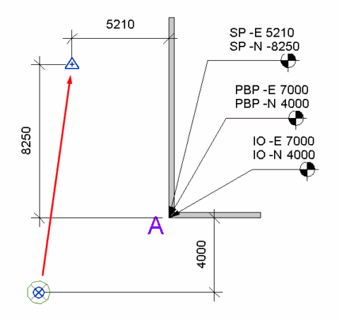
Now we already have some elements, and we are informed that point A has the following coordinates: (N -8250, E 5210, Elevation 1000).
We have no other file with the correct spatial reference (no DWG, no RVT).
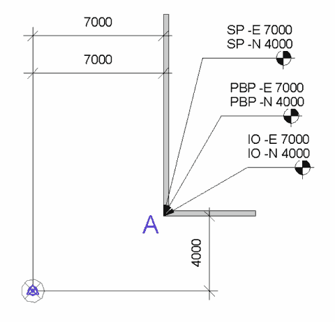
We are going to set the coordinates manually:
1. Go to Manage tab > Project location Panel > Coordinates menu > Specify coordinates at a point.
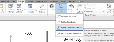
2. Select the point. In this case point A.
3. Specify the coordinates.
4. See that the Survey Point changes its position. The model has not moved, but the global (SP) coordinates of point A change. PBP has not moved. Internal Origin has not moved.
2. Share coordinates with a DWG
With this procedure we are going to establish in which location our model is actually placed (in terms of coordinates) with the help of a linked DWG.
But remember that we still are not going to move the modelled elements.
We have started modelling close to the Internal Origin of the file. That is the only care that we had when deciding where to start.
Now we already have some elements, and we are informed that point A is the same point A that we can find in a DWG file, that we know is in the correct location.
Now is when we are really going to share coordinates between the two files: DWG file and our RVT model. Share means that we are going to transfer the information from one file to the other. And this connection will remain.
Follow these steps:
1. Set the view properly
Go to a site view and ensure you are using “Project North”.
2. Insert the DWG.
Select the correct import units and CENTER to CENTER Positioning option.
3. Move and rotate the DWG Link
So that Points A overlap, and lines of the DWG are aligned with the walls.
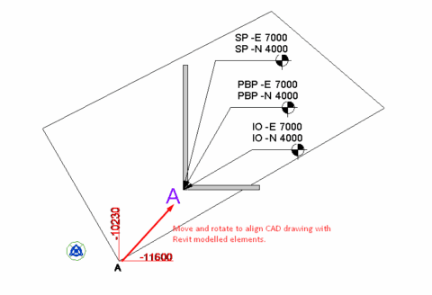
Remember, don’t move the Revit modelled elements. DWG Link and Revit file are still not sharing coordinates. They just overlap in the view.
4. Share the coordinates.
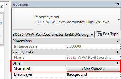
Select the DWG Link, and go to the Shared Site menu in the properties palette. We will see two options.
-
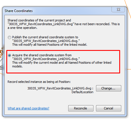
- Publish.It means “push coordinates”, and the action in this case would transfer the coordinates in the revit project (active file) to the linked DWG (link). NEVER publish when we are using a DWG Link.
- Acquire.It means “bring coordinates”, and the action in this case would transfer the coordinates from the linked DWG (link) to the Revit project (active file).
In this case we don’t want to change the DWG link, we want to modify the revit model, so we choose the Acquire option > Reconcile.
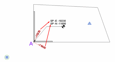
5. The Survey Point has moved.
Coordinates related to SP in model are now coincident with those in the DWG link. We have not moved model elements.
You can see that the SP has automatically been moved.
6. Remove the link
In most cases after this sharing coordinates process we can remove the DWG link or unload it. This will prevent us from moving it unintentionally.
Moving the DWG intentionally or unintentionally with no control which would result in us starting to experience issues with the coordinates.
7. Or stop sharing the site with the DWG
If we do not want to remove the link we could also stop sharing the site between the DWG link and the host project (it is like breaking the sharing option). This would also prevent some common issues.
If in the same project we have several models (which happens almost always) we can use the DWG link as the unique source of coordinates for all of them.
Once we have shared coordinates across all models, we will be able to work with them knowing that their global positioning is correct, that they share the same system, and that if we link one into another their location will match perfectly.
3. Share coordinates with other Revit files
With this procedure we are going to establish in which location our model is actually placed with the help of another linked Revit Model. In this second Revit Modelled the coordinates have been configured following any of the two previous procedures.
But remember that we still are not going to move the modelled elements in the host model.
Procedure is the same as with a DWG Link:
1. Insert RVT link
Choose the option Center to Center in the insertion menu (They still don´t share coordinates).
2. Move the link and rotate it
until it is in the right position relative to the host revit model.
When working with revit linked files we must not forget the Elevation. Linked file must be also moved in elevation to the correct position.
3. Select the link and go to the Shared Site Menu in the properties palette.
-
- Publish. To transfer pushing the coordinates from the revit host project (active file) to the RVT link.
- Acquire. To transfer bringing the coordinates from the RVT link to the Revit HOST project (active file).
In this case we don’t want to change the RVT link, we want to modify the revit HOST model, so we choose the Acquire option > Reconcile.
We advised to never publish when we are sharing coordinates with a DWG linked file. When we are using revit links we could do it both ways, publishing or acquiring, it only depends on which file contains the correct location of the project.
4. Reset coordinates
It could happen that we are in need of having the coordinates reseted, so that we have a file as if it were a new one, with the survey point in the initial position.
This could be for a number of reasons:
- Simply, we want to start over.
- We have acquired coordinates from a DWG/RVT Link and we realise that we have done it wrong.
- We have shared coordinates with a linked file, but at some point the coordinates of the project change.
In that case it is better not to try to move the linked files (either revit or DWG files), but reset the coordinates and start the procedure right from the beginning.
4.1 Reset the coordinates in the traditional way in any version of Revit
For resetting the coordinates, we need either a “clean” revit model or a “clean” DWG file. Have a clean DWG just with a circle with centre in World Coordinate System (WCS) 0,0,0. Or have a clean REVIT model with a model reference based on the Internal origin of the model.
And then, either if you use the “clean” DWG or the “clean” revit model, follow the same procedure:
- Save the DWG/Revit model and keep it for this and future uses.
- Insert the DWG/Revit model into the active model using ORIGIN to ORIGIN positioning
- Select the link and acquire coordinates from this clean file.
- Save the project.
- Remove the link.
- Save the project again.
- If necessary start the sharing coordinates process again from the beginning.
4.2 From Revit 2021
From this version of Revit there is a direct command to perform all the above procedure.
If you trust it, you will find it here:
Manage tab > Reset Shared Coordinates.
5. Insert generic DWG files
This is another case. We have already set up the coordinates of our Revit models, following any of the possible procedures.
At this point we need to insert some DWG links to complete the information in the project.
- They have to be in place.
- We know that the coordinate systems are coincident although the files are not sharing coordinates.
- These DWG links are not necessarily the one that we have used to acquire coordinates.
What then:
1. Insert the DWG link. Go to Insert Tab > Link CAD > find the file.
2. The view is in Project North.
3. Select the correct import units.
4.Select the option “Shared Coordinates” although files are not sharing coordinates. We will get this warning:

Do not panic. Just read and notice that this is just what we wanted, to align the World’s coordinates in DWG link with the coordinate system of the Revit model.
5. The DWG link lands in place.
6. When first we save the model after this process, we will get some additional options for saving positions of the DWG links. One menu for each DWG that we have linked. Again, don’t panic, it is just a matter of understanding each of the options:
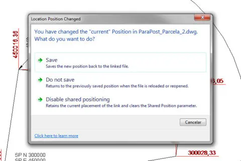
Save
We will be sending the information back to the DWG. It is not recommended as changing the DWG file is not a good practice.
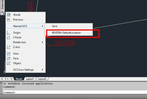
This change consists on creating in the DWG an additional UCS different to the World Coordinate System that would be the one used by Revit to insert the file.
Do not Save
nothing happens, we will be asked again later.
Disable shared positioning
DWG link will stay in the place that was inserted, but the connection between link and host is disabled, so that the DWG link is not changed at all.
This is the recommended option as explained also in Procedure 1.
Same applies for RVT links.
Tips & Tricks
- Always link and reload links in the same view mode: Project North or True North. It is easier to remember to use the Project North option since it is more usual in views.
- Do not ever try to move a linked file (nor DWG nor RVT) if what you want to achieve is to change host file coordinates. Remove it, reset the coordinates and start again from the beginning.
- When sharing coordinates with a file by acquiring them from it, unload every link in the model so that they are not affected by this change. If not, the active file will publish automatically coordinates to the links, and this can have undesired results if we are not very confident with this process.
- If you find that when inserting a DWG using the “Shared Coordinates” option it is not landing in the right position according to the World Coordinate system and with reference to the model, check in the DWG file the existence of an additional UCS. If that is the case, remove it.
Bottom-line
Coordinates in Revit are a very troubling subject for many people. They do not understand how it works because it does not work as it does in a CAD environment, which they feel is the intuitive way of getting it.
In any case coordinates are very simple if we understand that we have to model the project close to the Internal Origin of the file, and after that we will indicate which are the correct coordinates for that area, but without moving the model element. Instead we will move the Coordinate system origin.
Something important is also that:
-
- A file can have been configured with the right coordinates, but not share coordinates with any other file. Then they will not be ready for spatial coordination even though they can be located with the same coordinates.
- Sharing coordinates is a process to establish a connection between the coordinates information of two (or more) files, where the source should be unique for the models involved in the same project.
Bonus track.
Coordinates vs. Shared Coordinates
Schematic bonus track explaining when multiple files do and do not share coordinates: