

Beams
Modeling and configuration in Revit
BEAMS
File: OPE_Beams
Objectives
Understand how Revit beams work, how to model them and how to edit them.
Prerequisites
- User will be using Revit 2017 or more recent.
- User is a nice person.
Description
This guide explains how to set the model environment, how to face the modelling process and how to edit Revit beams once they’ve been created.
Procedure
General sequence
Before modeling, we have to identify or create the reference datums elements (Grids, Levels and/or Reference Planes), in which we’ll rely in order to model our beams. These reference elements can also be columns, structural walls and shafts.
Once we have identified the elements in which we’ll rely, we can model de beam by its central axis.
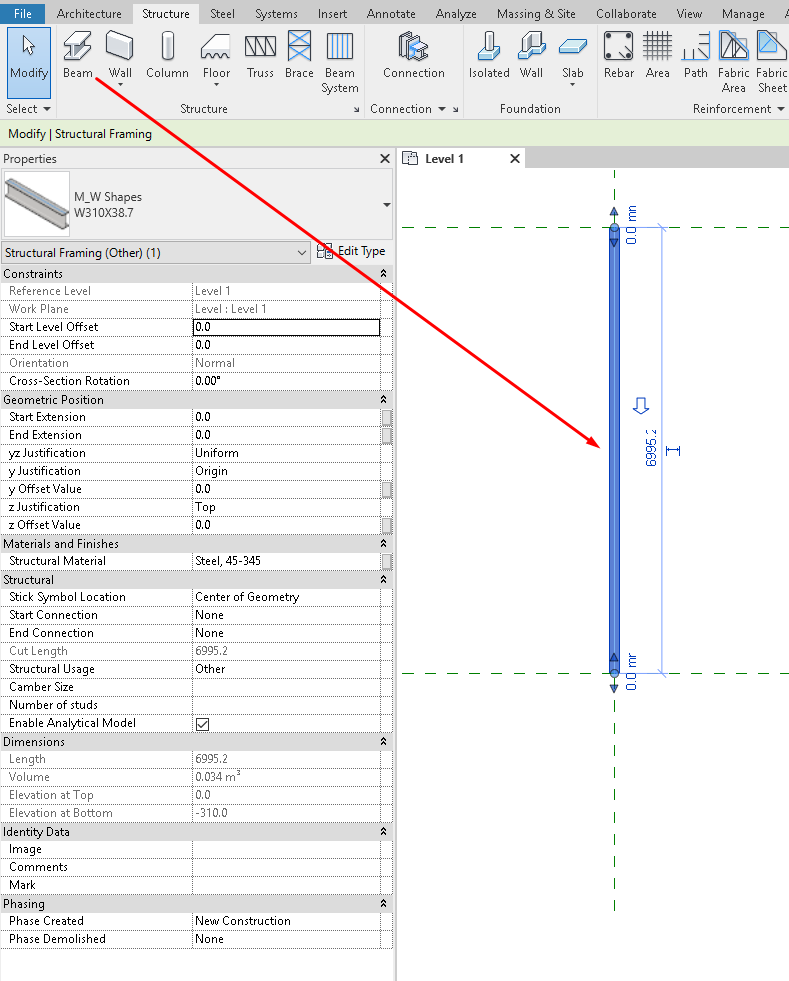
We can also create beams with the option "On Grids", which appears at the right part of the toolbar once we click Beam to create a new one, then we can then delete those created and not wanted.
Created the beams, check that they are placed at the desired level.
Sometimes they are created but can not be seen: verify that you are in the right view, with the appropriate Visibility and View Range Settings.
Properties
Type properties
In addition to the Identity Data common to all families in the same category, own parameters that could be added to that particular family will be displayed.
Under Identity Data, Keynote or Assembly Code can be assigned.
Instance properties
Constraints
Among the constrains that condition beams geometry, these are the ones that generally apply:
Reference Level
Work Plane: Normally for horizontal beams it matches the "Reference Level", but it is not always necessarily so. Any other horizontal or inclined working plane can be set to place the beams. They must always be:
- Levels
- Reference planes with assigned name
- Grids when working in elevation view
Start Level Offset: Indicates an offset with respect to the Level. If it is different from 0, the Work Plane is canceled.
End Level Offset: Indicates an offset with respect to the Level. If it is different from 0, the Work Plane is canceled.
Orientation
Cross-Section Rotation: Rotates the beam in the plane parallel to its section.
Geometric Position (Concrete beams)
yz Justification: Uniform/Independent. Uniform indicates that the variations in the position of the beam in the plane parallel to its section are uniform at the beginning and at the end of the beam. In Independent appears the possibility to edit the two extremes. Only use Independent in case of sloping beams.
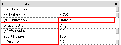
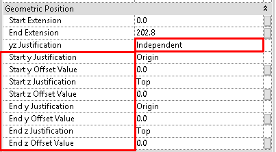
y Justification: Indicates the axis where the beam is justified in the plane perpendicular to the section. It is also accessible from the Tool Panel in a more graphical and more intelligible way.
y Offset Value: Indicates an offset for the previous justification.
z Justification: Indicates the axis where the beam is justified in the plane parallel to the section. It is also accessible from the Tool Panel in a more graphical and more intelligible way.
z Offset Value: Indicates an offset for the previous justification.
Material and Finishes
Structural Material: it is the material that will be used for quantity schedules, and to give certain graphic properties to those objects.
In addition, the Asset of physical properties of the material is the one that contains the physical parameters that take the analytical elements for the structural analysis.
Structural
Cut Length: This parameter is calculated automatically. Corresponds to the length of the beam.
Structural Usage: Selecting "Automatic" Revit indicates the structural use of the element.
Enable Analytical Model: If this option is selected the beam is enabled in the analytical model. If the model is not to be used as an analytical model or is not going to be exported to a structural calculation software, NOT checking this option will considerably improve the handling of the file.
Rebar cover indicates the value for reinforce covering.
Identity Data
Image: An image can be linked.
Comments: Comments can be added.
Mark can be useful as alternative identifier to “Beam Location”
Comments and Marks become useful when sorting and controlling the beams of a model.
Phases
As in the rest of elements you can indicate Creation phase and Demolition phase
Detail Level
It is recommended to think about the use of the lowest levels of detail: Coarse or Medium, especially when dealing with steel structure.
Beam schedules
It is convenient to generate a beam control schedule. The schedule must be addressed to “Structural Framing”. With the alphanumeric data you can quickly control the correct placement of the beams and their characteristics.
Cutting columns and beams
Cut
This tool (Modify Tab> Geometry Panel> Trim) only works with structural families that are configured with the Structural Behavior Material in Steel. And requires two elements to apply the cut of one against another.
Reference plane and cut
The ends of beams and columns can be trimmed at a specific angle using the Reference Plans and the "Cut" tool (Modify Tab> Geometry Panel> Cut). It is very practical, and works with all beams and pillars except those that are configured as Concrete in the family parameter Material for Structural Behavior.
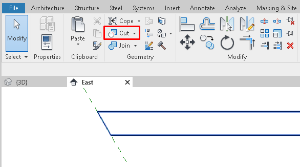
The reference planes can even be used to attach the pillars to them, in the same way as if they were attached to floors or decks.
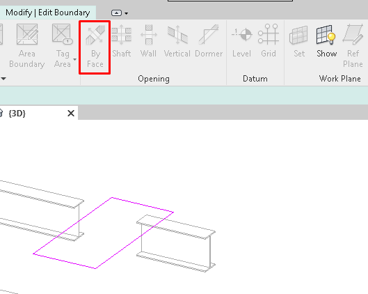
Opening by face
Another tool available: "Opening-by-face" (Architecture / Structure tab> Openings panel> By face).
With this tool you can customize the hole that opens into columns or beams, but with certain restrictions. The hole will always be through, and the casting will be done in one of the two main directions (horizontal or vertical) of the cross section of the element.
Cutting considerations
Cast in place: Cast in place components do not work to cut categories of beams and pillars although they do in other categories such as walls or floors.
Generic Model Families: Gaps can be used in Generic Model FAMILIES. In this case, you have to remember to activate the family parameter "Cut with empty when loading" in the families of Structural Frame (beams) and Structural Pillar. Cut both steel and concrete beams.
Masses
For special dumps, using masses is the best. They replace the components cast in place, which would have been our first shot. In this case not empty masses, but solid masses, with which to cut the beam or column.
Masses can be used as auxiliary elements, as we would with the cast in place components. They are better somehow, because normally it is already a category that is hidden in all the views.
In addition, by having a category of its own, the elements modeled will not appear in the tables of other categories, as cast in place components would, which must be assigned a particular category.
The only drawback is that they do not cut steel elements.
Tips&Tricks
- When a beam should be not horizontal, remember to use the Independent option at the zy Justification parameter.
- When a beam should be cutted, remember to consider it’s Structural behaviour material in order to decide the tool to cut it with.
- When modelling auxiliary elements to generate the cut, remember that some categories might mistakenly be considered in their categories schedules.
Conclusion
This guideline explains how to model and manipulate beam elements in Revit, considering aspects such as its start and end elevation, rotation, justification, and the cutting options available, based on the shape of the cut and the characteristics of the beam.
Wood furniture possesses one thing really natural concerning it.
There is this feeling of comfort, of attributes and of elegance that can easily be actually be located in hardwood home furniture.
Hardwood is actually born from the earth.
Para crear el armado de una viga ya dibujada, deberemos, antes de nada:
¿Definir el nivel donde vamos a trabajar y no activar el modelo analítico?
Hola José Miguel.
Aquí te dejo un tutorial de Autodesk de cómo modelar de manera simple armaduras, aunque en muchos casos hay que recurrir a otros procesos más complejos. No encuentro en el post que afirmemos lo que comentas.
Un saludo