

Advanced Topography and Roads
BIM Workflow with Revit
Advanced Topography and Roads
Index:
Procedure
1 Topographical Mesh Preparation
2 Use cases for topographic information
2.1 Scenario 1: Visual Reference
2.2 Scenario 2: Use for Views and Sheets
2.3 Scenario 3: Use for Dimensioning
2.4 Scenario 4: Use of Type and Instance Parameters
2.5 Scenario 5: Conversion to Revit Toposurfaces
2.6 Scenario 6: Conversion to editable elements in Revit
2.7 Scenario 7: Mesh display through Rhino
Objectives
- Work with Meshes DWG y Autodesk Revit.
- Understanding of the workflow and related actions to integrate into a BIM repository the infrastructure layout from its specific files.
Prerequisites
- We assume that the starting point are models with meshes and curves that create a layout. These elements have been created using a infrastructures modelling software like Civil3D or similar.
- Exchange format used will be DWG.
- We assume we will work with Autodesk Revit.
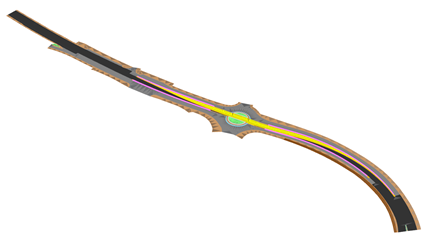
- The main information for the workflow will be the meshing of surfaces:
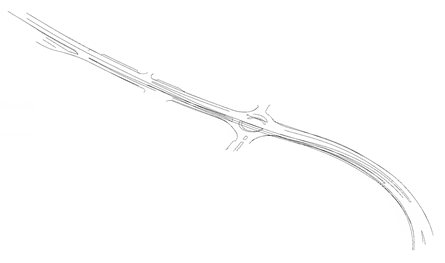
Additional information of level curves and edges will be of minor importance in this process. See 2.3.
Description
This document presents a workflow to integrate into a BIM repository the information resulting from programs for layout and modeling of infraestructures with DWG files.
This is a common problem in engineering work when combining BIM design of buildings together with the layout of the exterior infraestructures.
The proposed methodology is created from the experience acquired by Modelical working with Revit and mesh editors as Rhinoceros on the one hand, and on the other our clients requirements, who work with Civil3D and professional applications for topographies.
Procedure
1 Topographical Mesh Preparation
We make a distinction between the topographical meshes TIN and curves files. The information of this example has been prepared with Rhinoceros. However it is possible to do it with other softwares more popular like AutoCAD, although its functionality may be limited.
TIN files must be split by layers corresponding with materials or groups of faces which are to receive similar properties. This separation should be reflected in the layers of the corresponding DWG file.
TIN files processing includes:
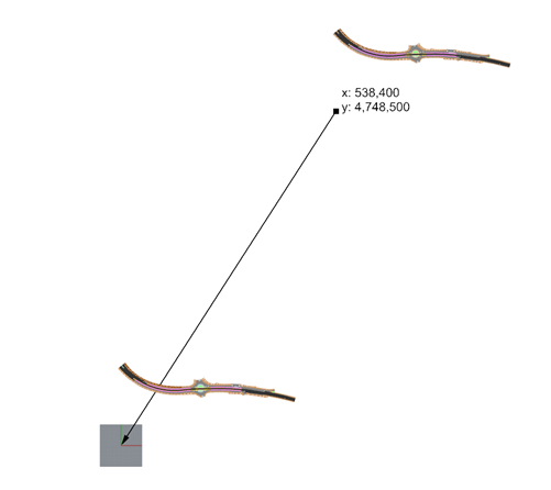
1.1 Relocation near the origin of coordinates
In order to get a better positioning and work accurately in Rhinoceros it is highly recommended to relocate the mesh close to the origin of coordinates. We can simply move the whole set and reflect this movement so as to acquire it as shared coordinates in REVIT.
1.2 Element separation by layers
To structure the information properly, elements should be split by sets of properties. Reflecting this separation in the layers of the DWG will help to maintain it between applications. This way Revit will include each layer as a subcategory, what will benefit us.
We should be careful with the separation of the elements trying to avoid faces wrongly classified:
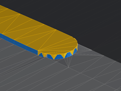
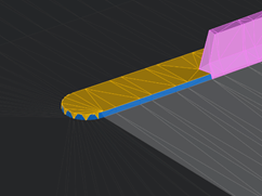
Samples of a mesh incorrectly split
1.3 3D faces join into mesh sets
In order to avoid too heavy files and sets of faces too complex, it is convenient to simplify and join all the triangles into meshes, with their vertex properly joined. We should keep those edges that we want to set as borders in REVIT.
1.4 Meshes revision and reparation for a correct representation
When working with meshes it is fundamental check that they are correctly joined, without corrupted triangles (with one or all their sides measuring 0) and with a consistent orientation of their faces normal.
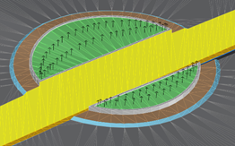
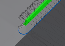
1.5 Exchange file
Once the mesh is prepared following the above mentioned steps, the mesh should be saved as DWG taking these precautions:
- Layer names will be correctly codified.
- The file should have nothing but the surfaces, properly combined, and the edges we want to use as lines.
2 Use cases for topographic information
The import process will vary depending on the use that will be given to the topographic files once included in the BIM platform. We will have to decide how we want to work with the meshes, if we just want them to be a visual reference, or we want to work with them once inside Revit.
2.1 Scenario 1: Visual Reference
In this case surfaces and topographic dimensions will not appear in the deliverables, and they are just needed to serve as a reference.
Procedure
This procedure consists in creating a new Site family and import the meshes jointly. After that this family will be loaded into the project and we will be able to control their visibility by the Imported objects parameters. Please note that the movement done in point 1.1 should be undo or at least controlled.
- Meshed surface in Autocad
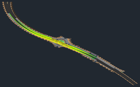
- Site family creation and DWG Import. Please note the import settings recommended. Mesh position should not be modified.
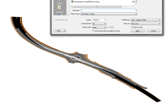
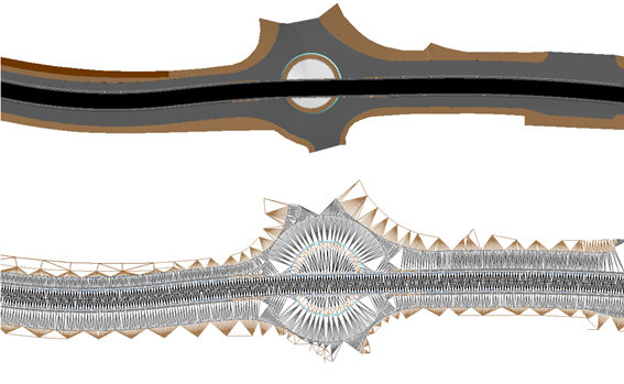
- Naming, saving and loading the family into the project. Topography seen in a floor plan view in both modes shaded and hidden line. Please note that triangulation makes impossible its use in 2D views.
2.2 Scenario 2: Use for Views and Sheets
In order to avoid the unpleasant effect of triangulation in hidden line views it would be necessary to add an intermediate step in the import process. This way we will get that the DWG file imported in Revit includes information about the visibility of the edges.
Procedure
In the absence of a more open method, the procedure will include an intermediate step in 3DS Max where we will make sure that the undesired edges stay hidden. The rest of the procedure is the same as 2.1.
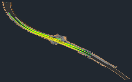
- Meshed surface in Autocad. Follow recommendations of point 3.
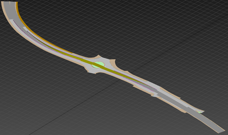
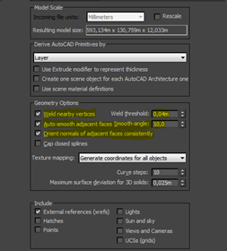
- Import the surface in 3DS Max. Note the configuration that will hide the triangulation in the surfaces.
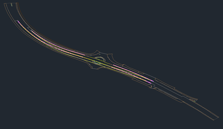
- Export the surface from 3DS Max to DWG. Note that interior edges have disappeared when opening the DWG file in AutoCAD.
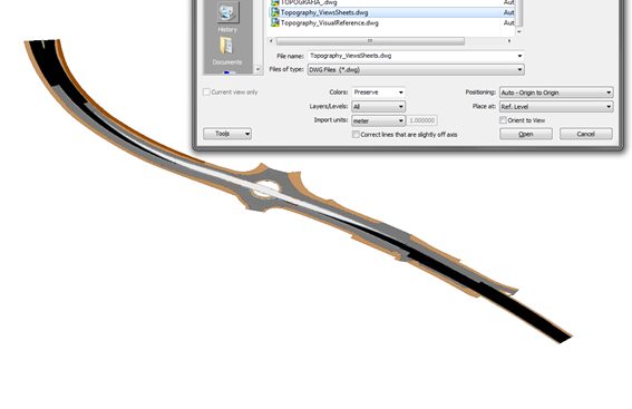
- Import the DWG in a Revit Site Family. Note the import settings recommended.
- Naming, saving and loading the family into a project in REVIT. Note that surface triangulation has disappeared from hidden line views and just border edges are shown.
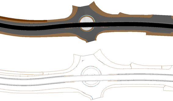
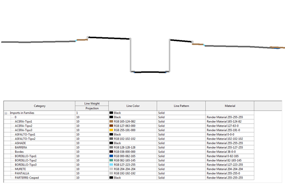
This family makes possible creating elevations and sections cause triangulation will not appear in hidden line mode. Line weights and graphic style can be modified from the object styles configuration.
2.3 Scenario 3: Use for Dimensioning
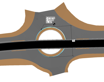
This scenario will be the same as 2.1 and 2.2 except for that in order to work properly, curves should be included in the family. This curves will be included as model lines that will represent borders that we want to easily reference in Revit.
Procedure
- Extraction of the Relevant Edge Curves. In this case Rhinoceros has been used to generate the lines of all borders.
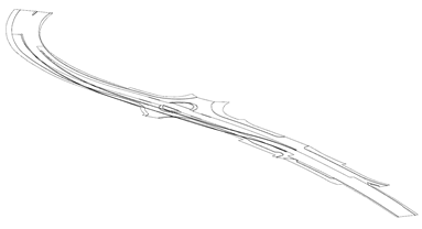
- Import the curves as model lines in REVIT. This step cannot be done from Revit, because it does not allow the import of 3D curves. An alternative method to solve this problem, will involve the creation from an Excel sheet or by the use of DYNAMO, a plug-in for visual programming that allows extended interoperability. After that, model curves are ready to be used to place dimensions.
2.4 Scenario 4: Use of Type and Instance Parameters
Another scenario may require that imported surfaces include additional information that could be shown in tags or schedules.
Procedure
The recommended procedure will split the original DWG reference file into smaller DWG files, one per layer, and then import them independently into the family, setting a visibility parameter for each of them. This way each layer will correspond to one type of the Site family and will be able to include independent values for parameters like area, material, volume, finish, use, etc. These parameters should be included as shared parameters.
We will have then a general family with a type for each of the sets included in the DWG layers, and it will be necessary to create one instance of each type.
Please note that properties included in each type will be able to be generated or read automatically.
2.5 Scenario 5: Conversion to Revit Toposurfaces
A possible scenario could be converting mostly horizontal meshes to patches of type toposurface of Revit. This procedure includes taking the mesh as a reference to create a toposurface from Revit using the algorithm that it contains - Delaunay - and modify its perimeter, which is always part of a convex polygon, to obtain the desired configuration.
Procedure
Export each shape that will split the surface separately. Import the meshes and shapes in Revit. Generate one single toposurface from all the points included in the mesh using the Revit tools. Split the curve meshes using the imported shapes.
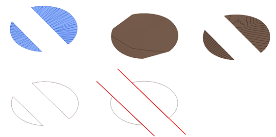


This procedure implies the complete reconstruction of the surfaces in Revit, and so it is much more laborious, being justified only when we want to interact intensely with the surfaces.
2.6 Scenario 6: Conversion to editable elements in Revit
With this scenario meshes can be converted into editable elements in Revit, like walls and roofs. Thus, it will be easier to interact with those elements, as they will offer more advantages when measuring and working with its properties.
Procedure
Import the mesh in Revit either within a mass family, or directly in a project by using an In-Place Mass. Afterwards, mass properties will be available and you can take benefit from them by using “wall by face” or “roof by face”.
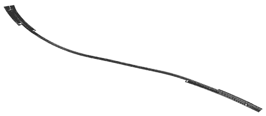
- Mesh conversion. Meshes are considered as Polyface Mesh elements, which creates problems when it comes to Revit recognize their faces. Therefore meshes have to be selected and converted with MESHSMOOTH or CONVTOMESH tools.
- Export each surface with different properties separately from AutoCAD. Equal to point 2.4, it will be necessary to split into smaller DWG files, one per layer, and then import them independently.
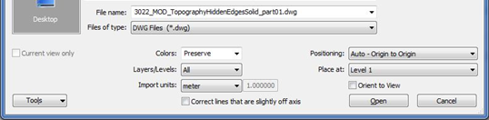
- Import each DWG in a Mass family in REVIT. Note the import settings recommended. It is recommended assign a visibility parameter to each DWG file when importing them, in order to create one family type per DWG. This way, a mass family will contain the whole mesh, but it will be splitted into several family types, making it easier to control.
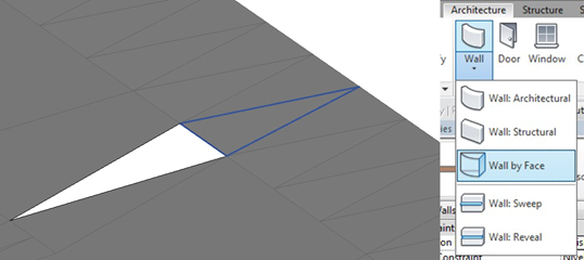
- Use of Roof by face or Wall by face tools with the mass family. Once the mass family is loaded into a project, it will be possible to create BIM elements from it (walls and roofs), by using the “Wall by face” and “Roof by face” tools. Afterwards, it would not be necessary to maintain the mass in the project, so it can be removed.
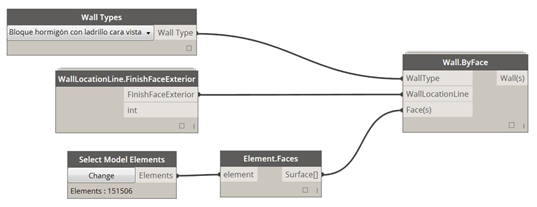
This is a tedious work if it is manually done, however it can be automatised by using Dynamo, or by programming through the Revit API.
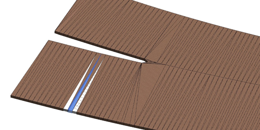
This scenario offers a high number of advantages in terms of the handling of elements in Revit, since it converts meshes into BIM elements fully editables as walls and roofs.

Both walls and roofs present different properties that should be taken into consideration when deciding which one will be chosen: Walls need one instance per face, resulting in a high amount of elements, however they offer benefits in adapting to any geometry. On the other hand, a roof can be formed by a high number of faces, which simplifies meshes creation and management, but it presents some difficulties when including faces with geometrical important differences, and it could result in a more laborious process.
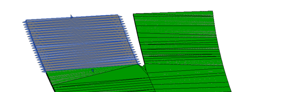
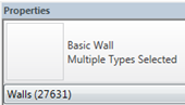
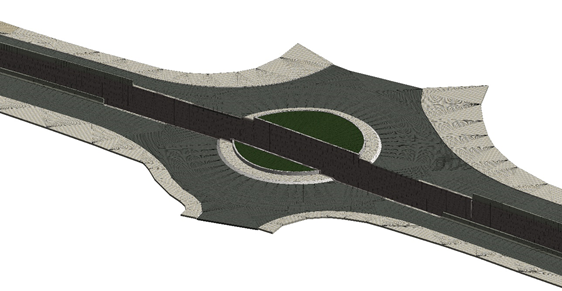
On the other hand, it is important to consider that this method creates a large amount of elements, and that can result in a difficult management of the model. For this reason it is highly recommended place those elements in a new file and then link it to the project model.
2.7 Scenario 7: Mesh display through Rhino
Rhinoceros could be a useful tool that can help significantly the work with meshes before loading them into Revit. In Rhino the mesh can be transformed in a geometry with thickness, achieving something similar to real construction, but with lighter elements in the model. As a counterpart to step 2.6, it will not be possible to modify the properties of this new geometry once it is loaded into Revit.
Procedure
It will be necessary working with each part of the mesh separately in Rhino. DWG files import, mesh conversion to geometry with thickness, and then import them directly in a project model in Revit as a Model-In-Place element.
- Export each mesh with different properties separately from AutoCAD. In order to get a better result in terms of its graphic display in Revit, it is recommended to repeat the steps explained in point 2.2 concerning the exportation to 3DS Max and posterior importation in AutoCAD. Afterwards, it will be necessary to split the file into smaller DWG files, one per layer, and import them independently in Revit.
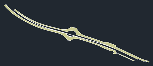
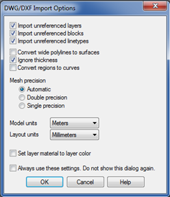
- Import in Rhino. Note the import settings recommended.
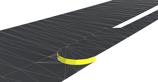
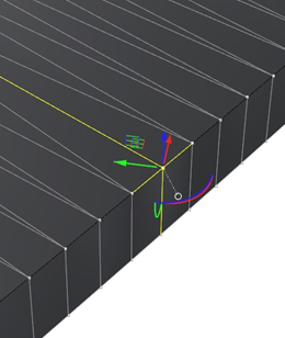
- Mesh work in Rhino. The aim is solving possible defects of the geometry, as shown in point 1, and create a shape with thickness from the mesh.
- Correct possible geometry errors and divide into simpler parts if necessary.
- Duplicate the border of the mesh by using “dupborder”.
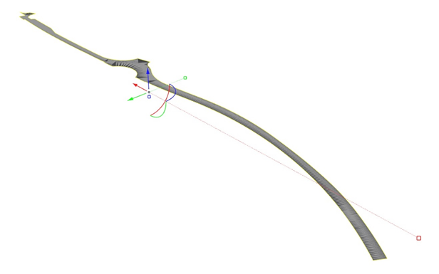
- Extrude that border with the desired thickness by using “ExtrudeCrv”.
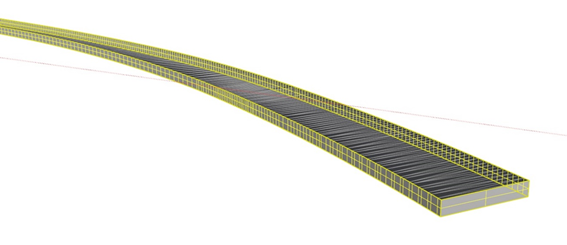
- Convert the surfaces created to meshes by using “Mesh from surface / polysurface”.
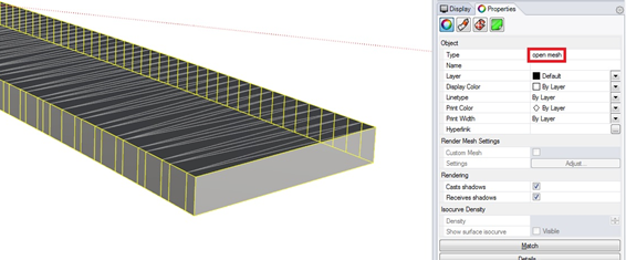
- Copy the original surface placing the new one on the other side of the extruded meshes in order to “cover” the geometry.
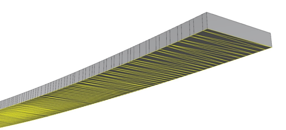
- Join the resulting meshes using “Join”. It is important to avoid duplicated vertex for each face. It is possible to solve this problem using “Weld vertices”.
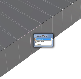
- Export the resulting geometry from Rhino to DWG
- Import from Revit. The best way to proceed would be by using Component > Model In-Place, selecting a category, and then importing the DWG file with the same settings used in the previous sections.
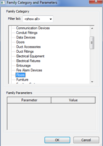
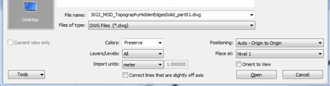

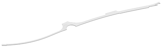
This method creates an accurate geometry, easy to handle in a Revit model. It also has a category in Revit and its graphic display meets the demands. Revit recognizes this element as an entity, working differently with its cut lines and its projection lines.
On the other hand, this method needs a previous work with the mesh in Rhino, taking each layer separately.
Tips & Tricks
Known limitations
- Proposed methods (with the exception of point 2.6) assume that the topographic information will be taken as a reference for modelling in Revit. All operations concerning editing, measuring and cutting of those meshes should be done in the native software that generated them. None of the proposed procedures allow editing the meshes, just its visibility properties. In 2.6 Scenario, the geometry of the meshes is converted into BIM elements, that can be edited individually, but with the disadvantage of being linked to the original mesh. In any case it is recommended to modify the meshes in the native program.
- Meshes, despite being robust geometries, cannot be used in Revit when cutting or modifying any BIM native element. Their faces cannot be used neither as reference planes when modelling or dimensioning. See point 2.3.
- Revit is not able to distinguish between cut and projection curves in open meshes.
- The colour assigned to an imported subcategory that includes a mesh will only affect the colour of its edges.
- In order to control the colour of the surface, it will be better to do it through the material assigned in the object styles window. It should be taken in consideration that patterns cannot be applied to the meshes. Thus, the shaded colour is the only thing that can be modified.
- It is not possible to place a spot elevation on a face of an imported mesh.
- Just in certain cases, references can be taken on the edges of an imported mesh. See point 2.3.
- The procedure described in point 2.5 only applies to surfaces that do not have a high slope and that can be reconstructed using the Delaunay triangulation of its vertex.
- The procedure described in point 2.6 sets an exception from the other methods in terms of the handling of the elements in Revit, because it will be formed by BIM elements. It presents some difficulties when working with those files due to the large number of elements that it creates.
Automation possibilities
This procedure is a conceptual test that approaches the flow of information between layout and topography applications to Revit in a manual way. This method can be improved by automation and programming in the following points, whenever considered working with applications which dispose an API, as AutoCAD or Rhinoceros:
- Mesh translation near the origin. It is possible to make this change automatically and revert it once is imported in Revit when configuring the shared coordinates, improving the accuracy of the whole.
- Separation of the elements in layers. This is only possible when the software that creates the DWG files includes this functionality. However, it is possible to generate automatically the DWG files that we need in scenario 4.
- Meshes joint in sets. This step is susceptible of automatization if the layer separation is properly done.
- Revision of the meshes. Certain tasks related with the revision and reparation of meshes could be done automatically but only in some applications that offer this necessary functionality, as Rhinoceros. Try to implement it natively in other applications, even if they have API, could be unprofitable.
- Metadata extraction from meshes. Certain data that the mesh contains in its DWG format or others that you want to calculate can be imported and assigned as parameters in Revit. This process can be mostly automatised by combining the different APIs involved. Working with configuration files XML could work. This files would save information for the mesh as a whole, each layer, as well as data related to its position, units, origin, uses or properties.
- Family generation and meshes import. This point is highly automatable although point 2.2 method implies a step through 3DS Max, an application that is not common in BIM workflows. It is necessary to find an easier alternative for generating meshes without edges.
- Generation of BIM elements from the mesh. Walls and roofs creation proposed in point 2.6 could be tedious if done manually, but it is a method easily automatable with Dynamo or programming in the Revit API.
- Generation of geometry with thickness in Rhino. Method 2.7 needs a work with the mesh in Rhino that can be improved by using Grasshopper.
Conclusions and next steps
Previous points sketch a simple methodology for the integration of topographic meshes in BIM models with Autodesk Revit.
In order to complete this procedure, next steps will be:
- Development and adjustment of the procedure properly for a particular project.
- Detail every step described in the methodology.
- Development of a scheduled routine to automate the processing, exportation and importation of the surfaces in Revit.
Associated files
# | Name | By | Description |
1 | MOD_TopographyWorkflowSample_R1.0 | RME | Sample file with results from 4.1,4.2 y 4.3 |
2 | MOD_TopographySample_R1.0.3dm | RME | Sample of topography worked in Rhinoceros |
3 | MOD_TopographyHiddenEdges_R1.0.dwg | RME | Topography mesh with hidden triangulation. See 4.2. |
4 | MOD_TopographyTriangulated_R1.0.dwg | RME | Topography mesh exported directly from [2] |
5 | MOD_TopographyWorkflowSample_R2.1 | ARD | Sample file with result of 4.6 |
6 | MOD_TopographyWorkflowSample_R2.2 | ARD | Sample file with result of 4.7 |
Buenos días.
Muy interesante y exhaustivo el artículo. Estoy comenzando en esto del BIM, y me han surgido algunas dudas después de leerlo, por si fueran tan amables de aclarármelas:
– 4.3 Escenario 3. Uso para Acotación. Apartado 2: se habla de utilizar Dynamo para la creación de curvas de modelo, a partir de un fichero excel. He estado haciendo pruebas en Dynamo, cargando un excel y dibujando las líneas con el comando Line.ByStartPointEndPoint, pero las líneas dibujadas en revit no son ni acotables y ni marcables. ¿Qué comando puedo utilizar en Dynamo para que me pueda dibujar en revit curvas de modelo acotables y marcables?.
– 4.1 Escenario 1. Referencia Visual. Apartado 2: habla de la creación de una familia site. Mi duda en este caso es que es una familia site y como puedo crearla.
Gracias de antemano y un saludo.
José I.
Gracias José por visitar Modelical.com y leer nuestras guidelines.
Sobre el uso de Dynamo, creo que te falta generar una Model Curve a partir de la línea de Dynamo.

La curva resultante es acotable con Spot Coordinate, usando la elevación.
Puedes crear una familia Site empleando la plantilla correspondiente cuando creas una nueva familia. Si tu Revit está en Español creo que has de buscarlo como Emplazamiento o Emplazamiento métrico.
Espero haberte ayudado.
Perfecto, todo aclarado, muchas gracias.