

Creating Rooms and Color Schemes
Operation in Revit
Rooms and their mysteries
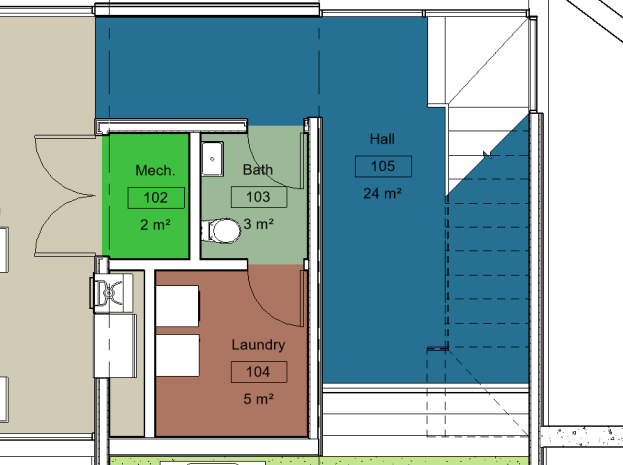
Objectives
- To be able to create a room in the corresponding phase, with walls or room separation lines as delimiters.
- Create room color schemes according to their parameters
Requirements
- The user will use Revit, any version
- The user has basic knowledge of modelling
Description
- Rooms belong to a Revit category that does not have different families or different types, so there is only one type of “Room” available.
- Rooms define spaces delimited by certain categories: walls, columns, floors, ceilings, roofs, curtain systems, or room separation lines.
Those elements can be either in the active model or in any of the linked models, as long as this option is active in the link properties. - Rooms are assigned to the level associated to the view in which they are placed.
The procedure
Bounding elements - Building components
When the boundaries are building elements (walls or columns), it is enough to select the "Room" button, within the Architecture tab. And then, select a contained point within a closed space. If the space is not completely enclosed, the Room will still be placed in that point, but it will have a standard square perimeter, without covering the actual space that has to be defined.

In order for the walls and columns to define a room boundary, they have to have the corresponding parameter marked in the element instances properties (Properties window).
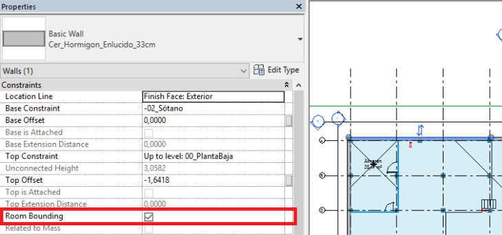
In some occasions there can be two adjacent spaces (physically separated) that should be measured as one, as it could be the room of a hotel with the incorporated bath. In that case, the separating partition should be configured to NOT be “Room bounding”.
Bounding elements - Room separation lines
We can also generate a room from room separation lines, which are abstract elements (do not represent a building component) that serve to delimit areas without a physical element. This can be practical in the design phase, simply to create spaces, or to differentiate spaces that are not physically separated but that should be measured separately as would be the case of a living room-kitchen, or a patio with a porch.
In this case, go to Architecture tab > Room&Area panel > Room separator.
You only have to select the tool, and draw the line as if it were a detail line.

Placing the Rooms
After having a closed contour, the Room can be placed inside it. If the room does not fit the boundaries, it is because the contour is not actually closed. We will then have to check the vertices of the polygon that defines the contour of the Room, whether this contour is shaped with construction elements or with Separation lines.
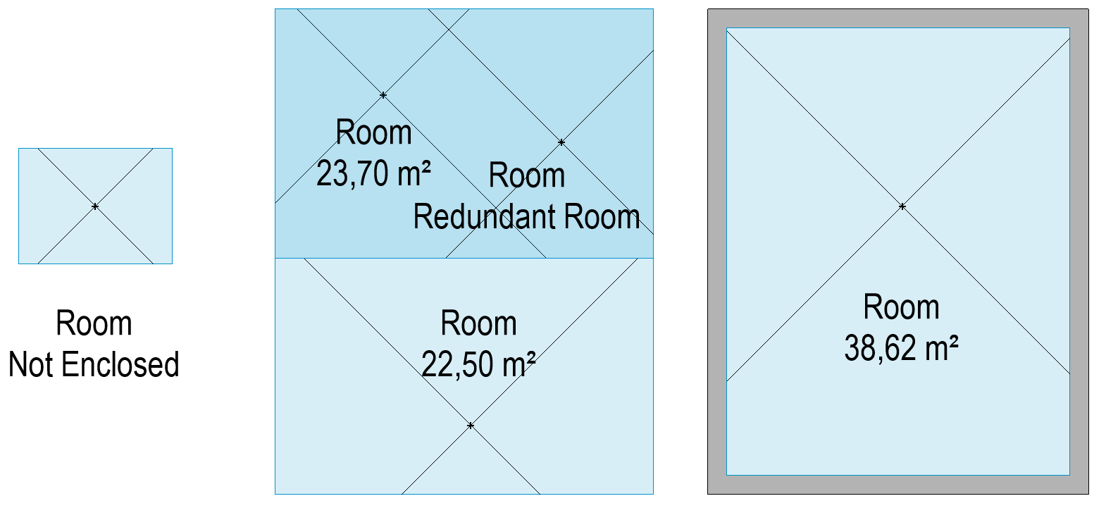
The procedure to create a Room is very simple, but you have to be careful to not have "Not Enclosed" rooms, which would mean having either rooms without closed boundaries, or overlapping rooms (redundant rooms).
In addition, the rooms are placed on one level and in one phase, and it is impossible to modify either of these two conditions later. In other words, a Room cannot be moved from level 1 to level 2, nor its phase be changed.
Rooms can be copied from one level to another with the copy/paste option, and in the same way they can be cut/pasted, but never moved.
Same with phases, to change the phase, the corresponding Room must be deleted and a new one has to be placed in the correct phase. As with any other Revit element, the “Demolish phase” can be defined as needed.
Visualization
Depending on the visibility overrides of the active view, the room can be seen in one way or another:
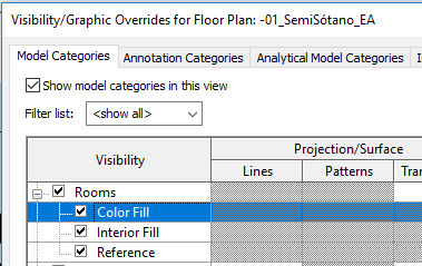
In the Categories tree, under the Rooms there are three additional subcategories whose visibility options can be configured independently:
Color Fill: It is necessary to have this checkbox activated if the interior of the room has to be visualized with colors. colors will be assigned through the “Color Schemes”.
Interior Fill: It allows to see the rooms with a blue shaded color by default. This shading is not printed on the plans, and only serves as a working tool, to visually identify the limits of the room in a simple way.
Reference: It consists of a cross that marks the center of the room. This center can be changed. It serves to verify that the room is referencing the space that you want to point out. When labels are placed, they often are moved to make the drawing more readable, and there can be confusion with the space they are labeling. In addition, this cross is the way to move a room around on the same level, from one space to another. Moving the cross, the whole room will be moved.
Color legends
Once the rooms of the project have been modelled, we can generate tables that follow a specific “color scheme”. This is one of the most interesting applications of Rooms in a project.
Legends
First, and to ensure that the color scheme to be configured or chosen for the view is actually displayed, it is necessary to activate the subcategory "Color Fill" within the view visibility menu, as explained above.
Then the "Color Legend" can be generated. For this purpose, and having a plan or section view active, select the "Color Fill Legend" button within the "Annotation" tab.

This object is nothing more than a "Legend" that summarizes the colors assigned to the Rooms according to a property of the same.
If this object is placed in the active view, the legend will appear in the floor/section view, although it will not yet have any content. The content appears when the "Color scheme" assigned to the view has been configured.
Color Scheme
There are two ways to actually display the contents of the color legend for a given "Color Scheme":
- Select the placed legend object and the option "Edit Scheme" appears in the Edition menu.

- Or within the view properties there is a parameter: "Color Scheme" which establishes which of them (of those existing in the project) is assigned to the view.
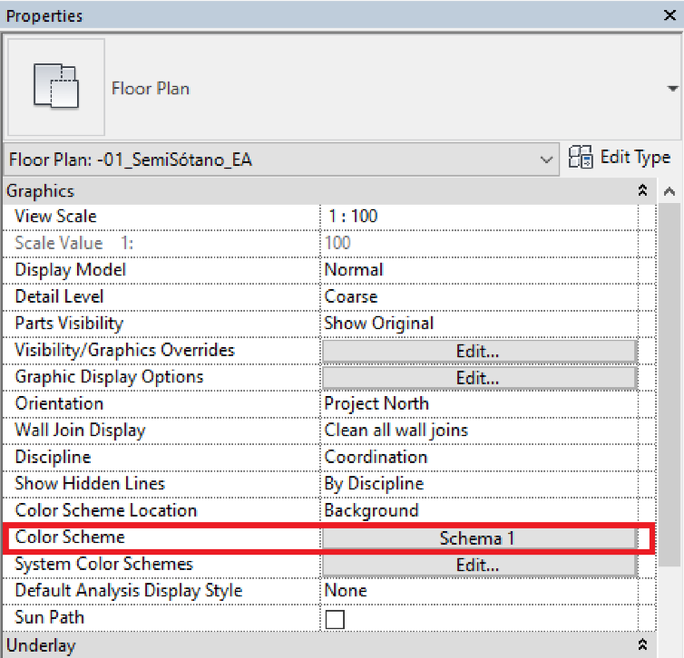
In both ways, the menu for creating and editing the “Color Scheme” will be opened.
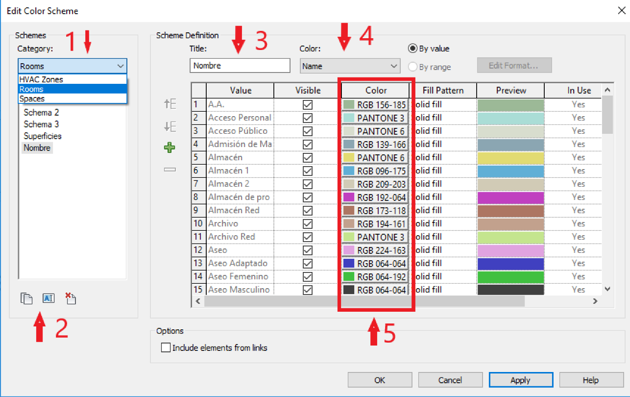
Steps to follow:
- Select the category to apply the color scheme. There are Color Schemes for "Rooms", but also for "Spaces" and "HVAC Areas", which are two other similar categories.
- To create a new scheme it is necessary to duplicate an existing one.
- The "Color Scheme" has to be named.
- Select the parameter according to which the rooms will be colored: Name, Department, Surface...etc (any of the parameters contained in the room, OOTB or any added custom parameter)
- Customize the colors and shading patterns be displayed.
Once these five steps are followed, the "Color Scheme" is defined, and can be applied to any plan or section view as if it were a template. In fact, in the view templates, the default "Color Scheme" can also be defined, as any of the other view parameters.
Tips and tricks
- Pay attention to the phase and level on which the room is placed, it cannot be modified once it is located.
- Rooms that are deleted from view are not removed from the model. The only way to permanently remove them is to delete them through a Room schedule.
- In the “Color schemes”, you can set the same color for two different room parameter values, as well as hide some rooms
- The display of the "Color Legend" corresponds to a type (family > type), which can be customized, and thus have different displays of that legend. You can change styles, size, font color, size of color boxes, etc...
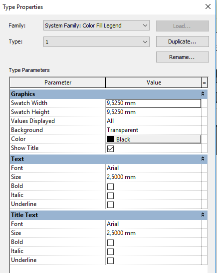
- In a view, only the rooms that are visible in that view will be shown, although the "Color Scheme" includes all the rooms in the project.
If it is necessary to make a legend with all the rooms in the project, regardless of whether they are shown in the active view or not, select, within the properties of the color legend, in the chapter on Graphics, the option: "Displayed values" -> "All", instead of "By view", which is what appears by default. - "Color schemes" can only be set in Plane > Plan views, but not in Reflected Ceiling Plans.
- Colors can be applied to rooms with the View Filters. But that setting is only visible, NOT printable.