
Views
Operation in Revit
Views
Objectives
- Use view types to quickly apply graphics properties and view templates to new views.
- Learn how to navigate views, create dependent views, organize views in the Project Browser, create view lists and view types,
- Modify view properties to change the view scale, detail level, visual style, orientation, and other properties of the view.
- Difference between callouts and drafting views.
- Understand visibility related to the different disciplines.
Prerequisites
- User has basic skills in BIM modelling with Revit Software, and understand the language used.
- User has notions about the data structure in models.
- User has basic notions of parametrization.
Description
Views are how we are able to see our 3D model (and 2D details).
Revit has many View Types:
- Floor Plan Views
- Reflected Ceiling Plan Views
- Structural Plans
- Area plans
- Elevation Views
- Section Views
- 3D Views
- Camera Views
- Walkthroughs
- Detail Views
- Drafting Views
- Legends
- Schedules
Procedure
View control
Description
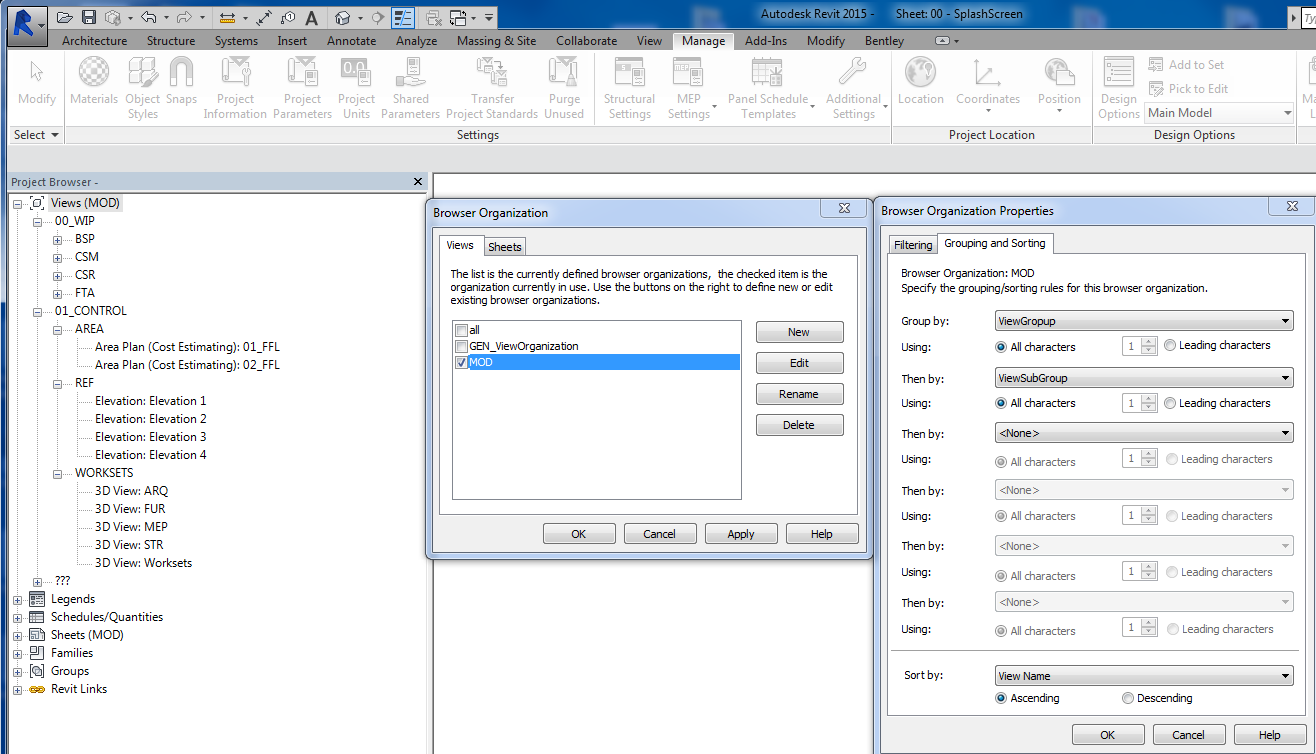
- Sometimes it is necessary to sort the view in groups and subgroups depending on users who use the views or the uses for which they are intended.
The Project Browser can be set up as WIP (work in progress).
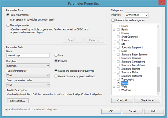
- Views are organised into VIEWGROUP and VIEWSUBGROUP. They are two custom parameters* applied to views that organize the project browser. If a view group has been set up already, it will appear in the view group drop-down. Type new names is required.
- Choose the option Project Parameter, it is not necessary to be Shared Parameter.
- Type a name, in this case 'View Group'.
- Choose the type of parameter, in this case "Text".
- You choose the heading under which you want the new parameter appear in the Properties window, in this case "Text".
- The parameter applies to instances and not by type, since we want to apply to each view in particular.
- Finally it should be noted to what categories of objects we want to add this parameter, in this case "Views"
- Every team member working on the project should have their own views to avoid any conflict.
- If View is sitting in view group/sub group '???' then no category name is yet assigned. Every view kept at “???” can be removed anytime by your BIM manager/coordinator.
- It is important also to create some views for workset control or any other views we need to keep the model classified.
WIP views
Work views are views that are used to model on them. They are in continuous change of aspect, since depending on what you want to model, we will change or not the scale of the view and modify their visibility.
It is important that each user has their own views on which apply the conditions without bother the rest of users. This is especially useful in the case of sections, since the high number of sections can appear when there are several people working on it, makes the model something uncomfortable and messy. It is recommended that each user have their own sections into their ViewSubGroup to allow others to create a filter and hide all those items..
Control views
They are views that are focused on specific issues. They allow us to view fast view to a given subject, always available, without having to configure it every time.
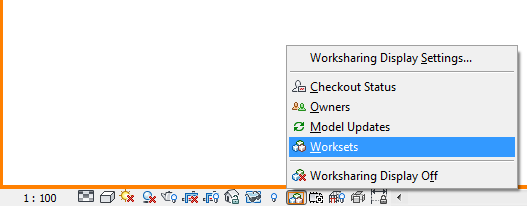
A good practice is to create a 3D view for each workset and name it properly. Set the visibility graphics for each 3D workset view to isolate the workset. This will provide a convenient way to visually check what is in a workset and to identify items placed in a wrong workset. There is also a tool that color the elements by worksets. It could be helpful to control the worksets.
Printing views
It is important that users don’t model through PRINT views. These views must have a scale and a certain visibility, factors that should not be changed.
We can decide if the views that are placed on sheets will no longer appear in Views. They will then only be accessible by expanding the relevant sheet. The drawing can then either be edited from the sheet or removed, in which case it appears in Views again.
Click on Views (right click) > New > Filter by sheet name = none
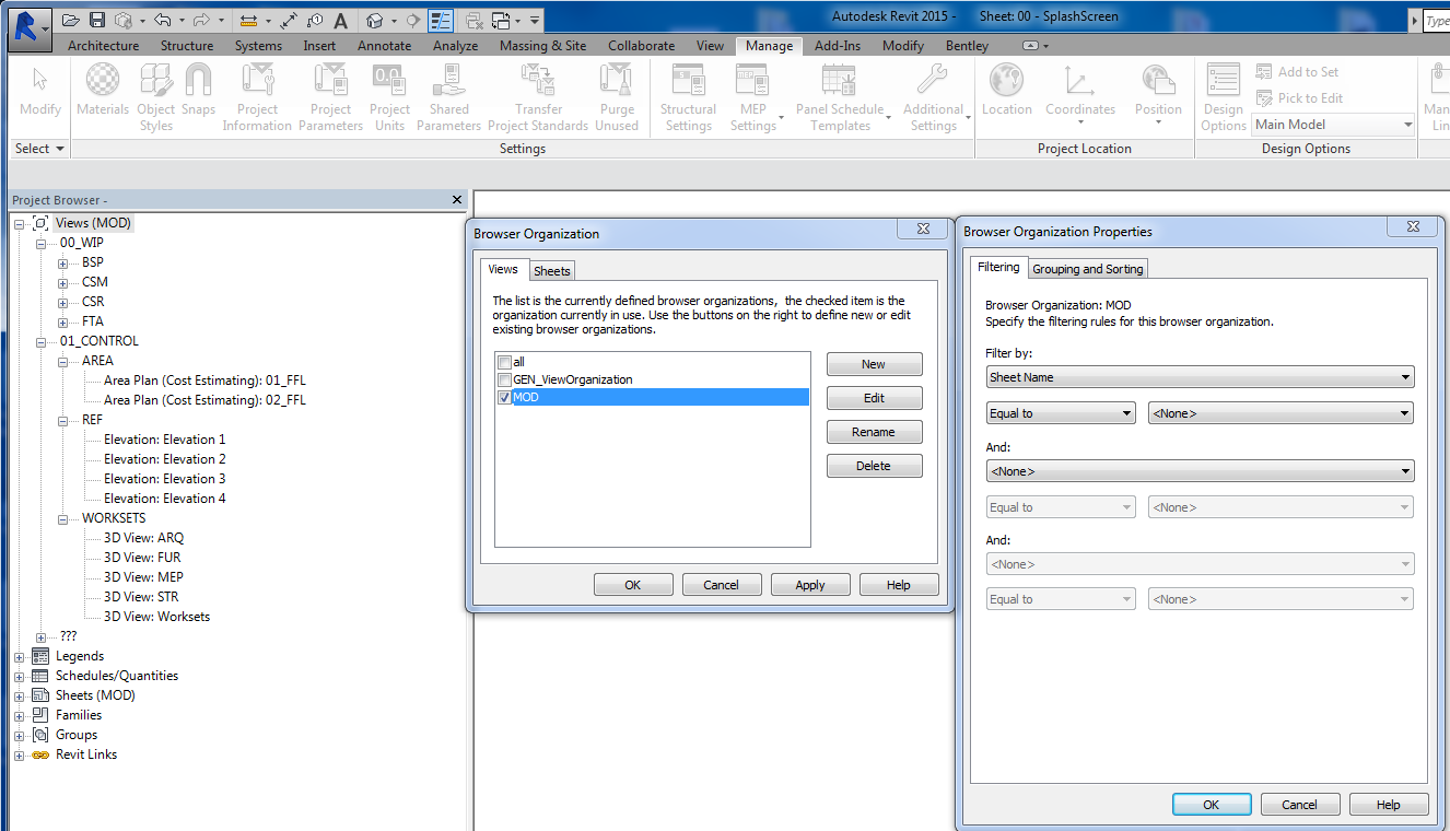
Suggested organization
01_WIP_XXX ( Working views). XXX ( Initials of all the people involved)
- Classification 1
- Floor plans
- Sections
- …
- Classification 2
- Floor plans
- Sections
- …
02_CONTROL (created to control)
Worksets
- ARQ
- STR
- …
Export
Navis
…
Coordination
03_PRINT (They are placed on sheets, they should have view templates assigned)
0100-Situation
- 0101-Site
- …..
0200-Areas
0201-GroundFloor
0201-FirstFloor
…
0300-Sections
0301-Section1
Create views
Definition
The views are the elements of Revit to "look" to the model. We can distinguish three kinds of views:
Graphics 2D
- Floor plans
- Sections
- Elevations
3D
- Axonometrics
- Cameras
Alphanumeric
There are schedules where the representation of the information of the elements is expressed alphanumerically, not graphically. They are data.
Graphics views
When starting a new project they usually appear several views already created.
Plan views
Floor plans in Revit are always associated with the different levels that are created in the project, and therefore there should be levels to create floor plans views.
To create a new plan view, go to View>Create the following options are shown:
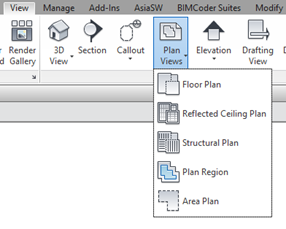
Floor plans
This option creates views that represent a horizontal cut of the model, looking down. Once selected the option the following dialog box appears:
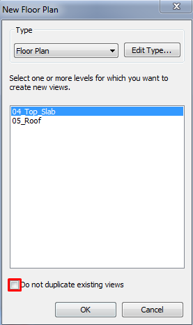
Choose the level to which you want to associate the drawing view. If you want to create a view of a plane associated with a level for which already previously there is a view, uncheck the box "Do not duplicate existing views".
Reflected ceiling plans
You choose this option if you want to create a ceiling view. In this case the "View Range" should be defined as if it is looked up.
Structural plans
A Structural Plan view is a view intended to represent structures. From a horizontal cutting plane look up/down. ("Up/down" is selected in the properties of the Structural Plan type)
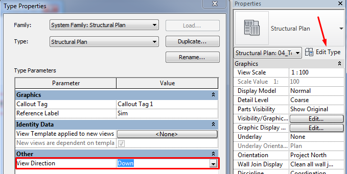
Plan region
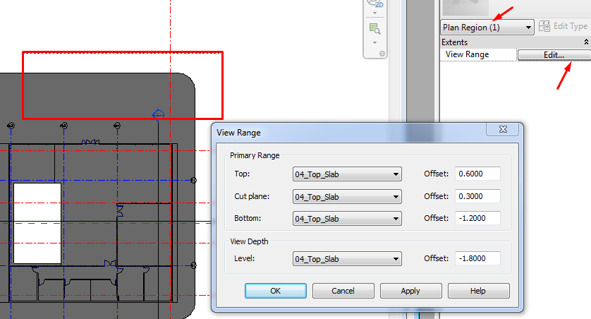
In a floor plan, it is sometimes necessary that a region has a different "View Range". In that case, the solution is creating a "Plan Region" in that view and specifically modify their "View Range".
Area plan
Area plans are views that show spatial relationships based on area schemes and levels in your model.
Areas are not necessarily bounded by model elements. You can draw area boundaries or pick model elements to use as boundaries.
When you add model elements, the area boundaries do not necessarily change automatically. You can specify how area boundaries behave:
- Some area boundaries are static. That is, they do not change automatically and must be changed manually.
- Some area boundaries are dynamic. They stay connected with underlying model elements. If the model elements move, the area boundaries move with them.
Elevations
By default a new project will already contain four elevations: North, South, East, West.
To create new elevations, go to View Create Elevation. The option is only selectable if plan view is active.
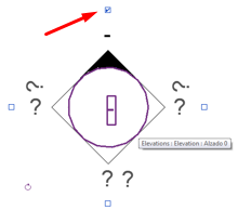
Selecting the symbol, can be selected at the same time the elevations that we want to be active. Elevations views will be created in the project browser, as you select each of the four orientations. You can move the elevation, and rotate, to align it to convenience.
By clicking on each one of the arrowheads of the elevation label, will appear the corresponding flat elevation view delimiters.
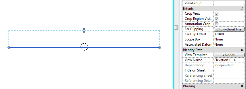
The offset plane can be moved, and modified it extension by clicking at the ends.
If the blue balls do not appear at the ends, you should check the “Crop View box” in the properties window.
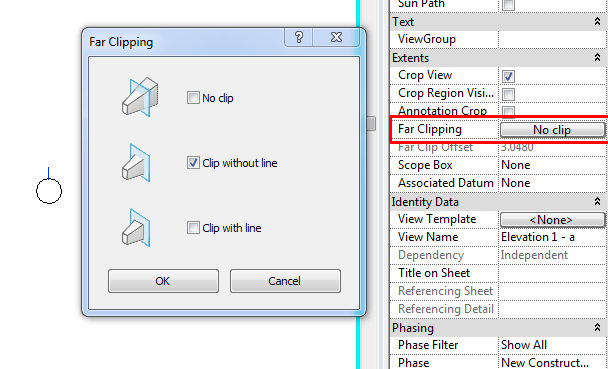
If it does not appear far clip plane, to modify the depth of view of elevation, you will have to choose an option in the window propertie: Far Clipping.
Sections
Views can be created in any plan view, elevation, or section, and defines the intersection of the created drawing and the model.
To create a new section must be active the more convenient view, and the tool is on the Ribbon>View>Create Section

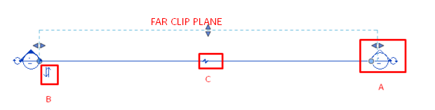
- A: A tag will appear at each end of the section. You can also vary the size of the region cropped, by dragging the blue arrow controls.
- B: You can turn the section, by the corresponding icon, to change the view of a side to another.
- C: Section line can be divided, by pressing the control of division. You can define the length of the section line segments thanks to the blue circles. This line does not have why appear in the drawing, without affecting what is shown in the section view.
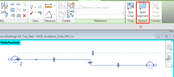
- D: To create a broken line of section there is a tool on the Modify Views Section Split Segment tab. Click at the point you want to divide the section, and then crawl the side of the line of section to the site you wish to place. You can only create broken lines which are parallel.

3D

Duplicate views
In project browser you can duplicate a view by pressing the right button and selecting one of the three options to duplicate:
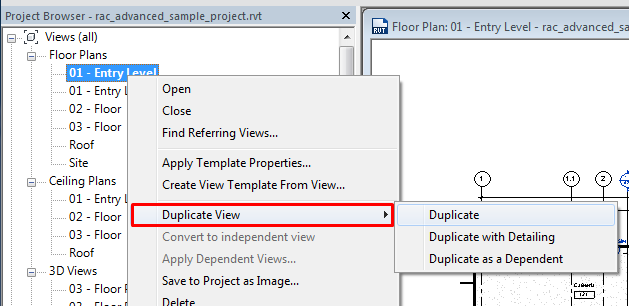
- Duplicate. In this way, the view will contain all model objects, but not the annotation ones (comments, detail lines, elements of detail,revision clouds etc...). The views remain as independent, so entities can be changed without affecting any other view.
- Duplicate with detail: In this way, the view contains both annotation objects and model ones.
- Duplicate as a dependent: In this way, the view contains both annotation objects and model objects. The views remain as fully dependent entities, changes made to them are reflected in the others, including view templates.
- The unique configuration properties that may be different between dependent views are:
- Clipping region
- Modifications graphics by element
View properties
When you have any item selected, the Properties window refers to the properties of the current view.
The families of views: floor plans, sections, 3D, also can have "Types".
View Template applied to new views
They are little used but may sometimes be useful, for example, if we have defined types of sections, “STR_Section”, the new views that are created automatically using those types can be assigned to a View Template which can determine its visibility, etc…
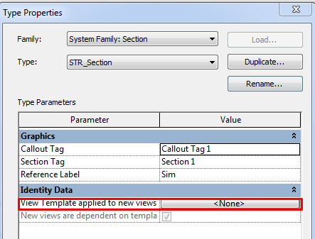
The new sections created with this type will contain by default the selected view template applies here.
Type properties
Section tag
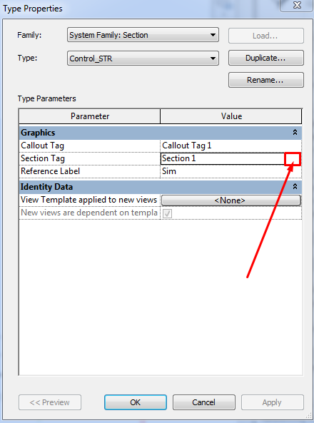
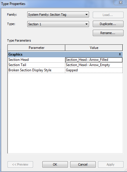
The family that is used as a Section Tag is selected. The Section Tag defines part of the graphics of the section. When you click the right button we see the definition of that family. It is a system family but that is made by loadable families, one for each end of the section symbol (may be the same). You can also choose the line pattern of the section line.
Instance properties
View Scale
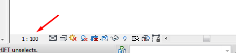
You can choose from predefined scales, or "custom". Its importance lies in that according to the chosen scale, it will vary the relative size of annotation objects such as dimensions or texts, and will also vary the thickness of the element's lines. This property can also be controlled from the menu that appears in all views in the bottom at right.
Display Model
- Normal
- Halftone. Model categories are displayed according to the settings configured in the Manage Additional Settings Halftone/Underlay.
- Do not display. Model categories are not shown.
Detail level
- Coarse
- Medium
- Fine
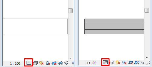
Each one indicates the level of definition of the elements in the view. For example, a wall made from various layers, in the medium and fine detail levels those layers are displayed, but in the coarse one, we will see just the outside limits.
Another example would be the metal profiles. The way we see them is quite different regarding the level of detail.
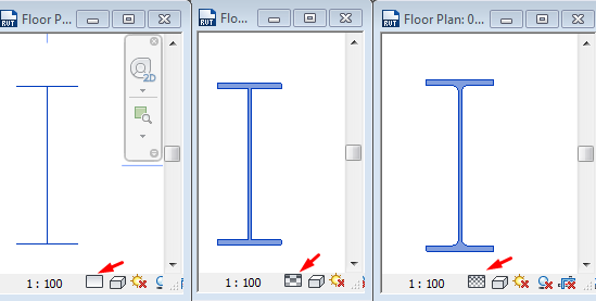
If the view does not require it, low-detail levels are always better because of the improvement of the performance of the model.
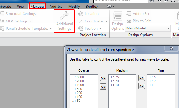
To create views, Revit assigns default detail in correspondence with the chosen scale, according to the available and editable table on the Manage Additional Settings Detail Level Ribbon. However this only applies to the creation of the view, then the level of detail can be changed at any time.
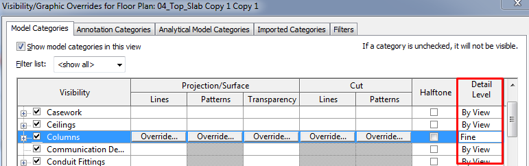
This property can also be controlled category by category in the Visibility/graphics menu.
Graphic display options
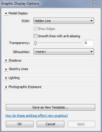
Model Display
You can choose from the different styles of visualization of the model. This property can also be controlled from the menu of icons that appears in all views in the bottom right.
- Wireframed: Only the edges of the model are displayed, including the lines that the view would remain hidden.
- Hidden Lines: Displays the model in such a way that hidden lines remain hidden, but without shading.
- Shaded: This mode applies shading to each object or instance according to the material and colors defined for them. When you select this option is enabled to choose between displaying the edges of the elements or not: Show Edges.
- Consistent Colors: Displays the surfaces according to the color of their materials, always in the same way, without taking into account the hypothetical incidence of light.
- Realistic: It applies to surfaces the color or pattern as defined in display rendering of different materials, taking into account the incidence of light. When you select it, the option is enabled to choose between displaying the edges of the elements or not: Show Edges.
- Smooth Lines with Anti-Aliasing: Select this option to display the edges "smoother". To improve the performance by using this option, you should check the "Use Hardware Acceleration" of the tab Graphics in the Options of the menu of the application.
- Transparency: You can select the percentage of transparency of model categories.
- Silhouettes: selects between the possible Line Styles to create a "silhouette".
Shadows
- Cast Shadows. It shows the bold shadows. The shadows are dependent from the settings of the "Sun".
- Show Ambient Shadows. It shows the shadows of 'atmosphere'.
Sketch lines
This is a very interesting option when we want a less "orthogonal" view. It allows you to convert the edges in line, simulating a sketch.
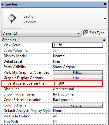
Hide at scales coarser than
If we have assigned the value 1:100 in this property to a section, in a floor plan view with 1:200 as scale, that section will not appear.
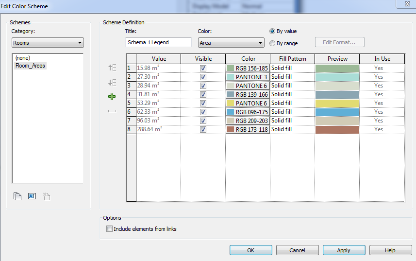
Colour scheme
Color schemes apply color and patterns to the following categories:
- Rooms
- Areas
- Spaces and zones
- Pipes and ducts
This button opens the menu to configure the color schemes.
Crop View
By checking the box, the extension of the view will be cropped, in such a way that it hides part of the model. The boundary is defined by the Crop Region that is activated in the following property.
Crop Region Visible
To edit the boundaries of the visible region, it is necessary to select this check box to make it visible.
- Edit Crop. By default the Crop Region is rectangular, “edit crop” tool can edit its profile and turn it into polygonal. If you use this option, it will activate the tool Reset Crop to return to its original state.
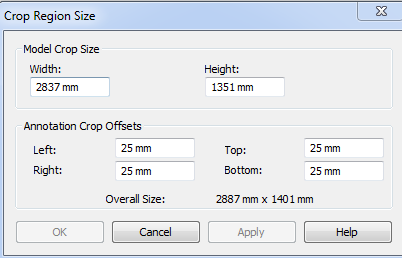
- Size Crop. Using this dialog box the perimeter can be defined of the Crop Region and the Annotation Crop in mm.

Annotation crop
The previous Crop Region delimits the vision of model categories. The Annotation Crop defines the vision of the annotation categories. If activated a second window appears when you select the Crop Region. Dimensions, texts, labels, which are within this second window will be displayed, if they are outside, they won’t be not shown.
View Range
The view range is a set of horizontal planes that control object visibility and display in the view. The horizontal planes are Top, Cut Plane, and Bottom
.
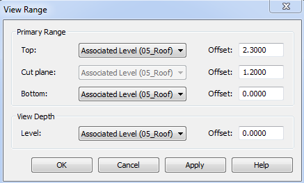
- The top and bottom clip planes represent the topmost and bottom most portion of the view range. MEP elements or non cut elements will be displayed if they are contained in between those two planes.
- The cut plane is a plane that determines at what height certain elements in the view are shown cut.
- View depth is an additional plane outside of the primary range. You can set the level of view depth to show elements below the bottom clip plane.
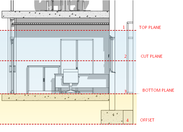
Visibility according to the view range:
- Elements within the boundaries of the primary range that are not cut are drawn in the element’s projection line style.
- Elements that are cut are drawn in the element’s cut line style. Not all elements can display as cut.
- Elements that are within the view depth are drawn in the beyond line style.
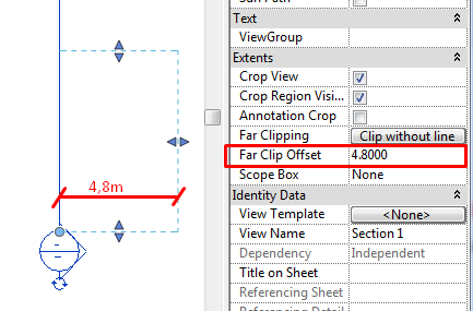
Far clip offset
Defines the distance between the section line and the depth that will be displayed.
Scope box
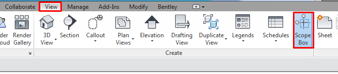
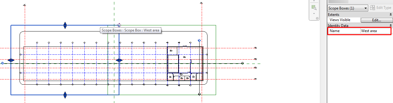
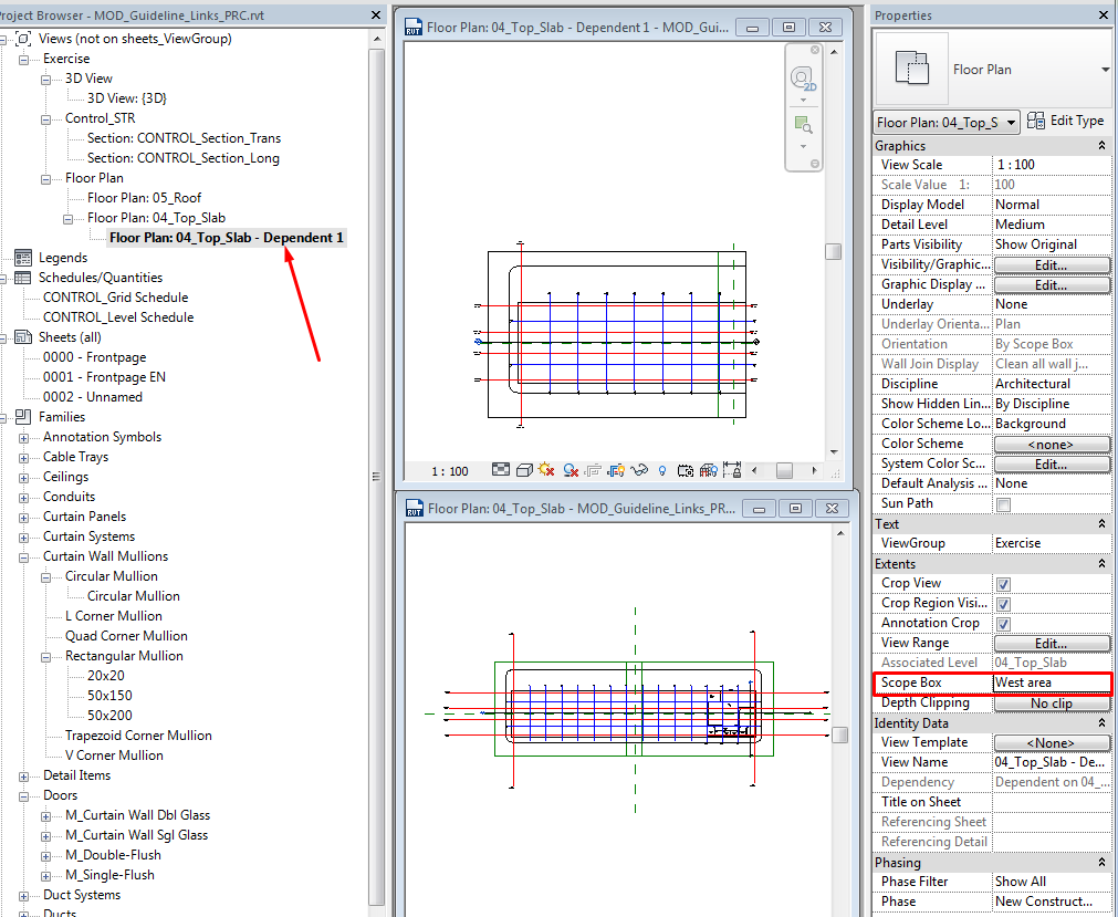
The Scope Box are 3D boxes that are used to define different contexts within a model. Once created, applied to the views thus controlling the view extension. I.e., if you apply a Scope Box at a view, this overrides the bounding outline of the Crop Region, the Scope Box "becomes" Crop Region. Crop View and Annotation Crop behave in the same way whether a Crop Region or a Scope Box.
It is quite useful when we have extensive projects, the views do not fit on the sheet and we have some dependent views. To get all portions exactly the same at all levels you need to apply scope boxes.
View templates
With this button we select what View Template apply to the view. See Graphics Management guideline.
View discipline
In the View Properties window you can find a “View Discipline” property.
The intention is to adapt the visualization for the different work disciplines, as long as what an architect, a structural engineer, or a MEP engineer wants to see or represent in a view is not usually the same.
That said, each View Discipline could be understood as a pack of default view settings.
There are six different View Disciplines:
- Architectural
- Structural
- Mechanical
- Plumbing
- Electrical
- Coordination
Disciplines are system-controlled, and cannot be modified.
Model elements will be shown or not, and they will appear in a certain way, depending on which View Discipline we choose.
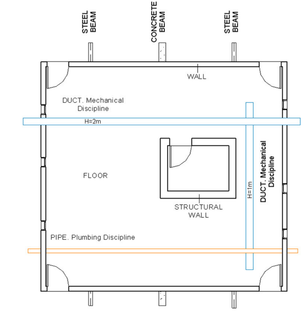
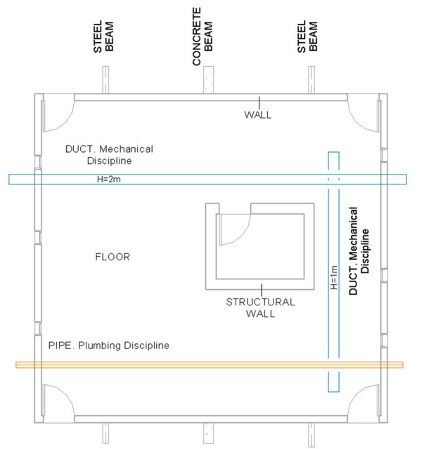
Let's start with a simple model (see first picture) with some elements corresponding to different disciplines. The Cut Plane in View Range is set 1.5m above the level, Top Plane 3.00m:
Coordination
- Every object in model will be shown according to Object Styles, or Visibility/Graphics Overrides if something has been changed there.
- Objects visibility and cutting elements will respect what “View Range” determines, unless those elements belong to MEP Categories (Mechanical, Electrical, Plumbing).
- Mechanical, Plumbing, and Electrical Categories will not strictly respect the View Range, and will appear as long as they are included in the Primary Range (between Top and Bottom Plane). Just because the intention in Coordination is to show every element in the view.
Architectural
- Every object in model will be shown according to Object Styles, or Visibility/Graphics Overrides if something has been changed there.
- Objects visibility and cutting elements will respect what “View Range” determines.
- Mep elements will only appear if they are between Cut and Bottom Plane.
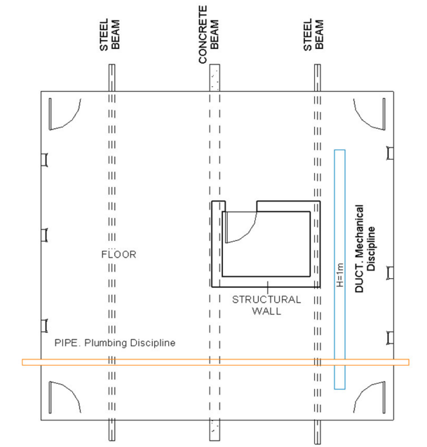
Structural
- NON STRUCTURAL Walls and Floors will be hidden. But not the elements (like windows or doors) hosted in them.
- Those structural elements (beams, columns, walls) beneath or behind other elements such as floors or walls will appear according to the Hidden Line sub-category in the corresponding Model Category (Object Styles or Visibility/Graphics Overrides).
- Other elements will be shown according to Object Styles, Visibility/Graphics Overrides and View Range.
Mechanical, electrical and plumbing
- All categories belonging to Architectural or Structural Disciplines will appear half-toned.
- Mechanical, Plumbing, and Electrical Categories will be shown according to Object Styles or Visibility/Graphics Overrides.
- Mechanical, Plumbing, and Electrical Categories will not respect strictly what View Range determines, and will appear as long as they are included in the Primary Range (between Top and Bottom Plane).
- When ducts and pipes overlap, the element below will appear in a Hidden Line style.
Detail views
When we climb up scale in views, it is necessary to complement the drawing and detail items obtained from the model. Revit provides two possible procedures for this process:
- Callout: Contains model elements.
- Drafting view: It is a clear space that is not directly associated with the model.
Callout
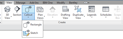
- It is a view which appears as a section or call. This kind of view usually represents a portion of the model more accurate than the other views. You can create a call from a plan view, elevation or section and then add some detail with the geometry of the model as a basis. They are created from View>Create>Callout.
- Once the call is complete, we can go to the tab (right click go to view) and hence we include elements of annotation and detail to complete the model. It should take into account that if we change any part of the model in this type of view, you modify all other views because you are changing a model element.
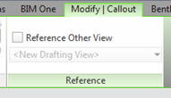
- When we create a callout, it allows us to make reference to a view already existing. This tool allows you to make reference to the same detail in different views. The same occurs when you create a section.
Drafting
- During a project, it is sometimes necessary to create a view that is not directly associated with the model: a drafting view. These views do not show any model element. 2D tools are used in this kind of view: detail lines, regions, components of detail, insulation, dimensions, symbols and text, or even you can import an AutoCAD detail.
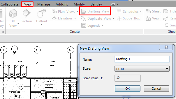
To create a drafting view we go to View>Drafting View.
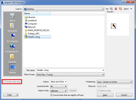
- To import CAD files as construction details, we go to Insert>Import>CAD. We must check that the scale of the view and the CAD is the same. In the window that appears you can customize some aspects of the import, paying special attention to the option "Current view only" which should be active.
Tips & Tricks
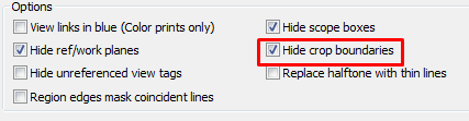
- Crop region visible: From the print options you can activate the option: Hide crop boundaries, if the Crop Regions are activated still will not be printed.
- To rotate a view in drawing without using the "Rotation on Sheet" you can use a Scope Box and assign the view of that Scope box.
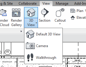
- When you need a 3D view it is very common to create a new view from the quick access bar. If you are trying it and it doesn’t work, it is because you already have somewhere a view with the default name {3D}.
Bottom-line
You can create different views of the building model, such as plans, sections, elevations, and 3D views.
In the building model, every drawing sheet, 2D view, 3D view, and schedule is a presentation of information from the same underlying building model database.
When you change the building model in one view, Revit propagates those changes throughout the project.